Introduction
Multiple concentric ring arrays (CRAs) share a common center and are advantageous over other array geometries in terms of all azimuthal scan capability, frequency invariant features, and lack of edge elements making them negligible sensitive to mutual coupling [Reference Elliott1]. Uniform multiple CRAs have equally excited array elements and have gained intensive attention especially in the use of direction finding, scanning, wireless, and satellite communications [Reference Reyna, Panduro and Del Rio2–Reference Jiang and Zhang6]. For example, in [Reference Reyna, Panduro and Del Rio2], the CRA is designed for the application of geostationary earth orbit satellites with isoflux radiation. For a reconfigurable isoflux pattern, design of concentric ring antenna arrays with 61 elements of disk-patch antennas is proposed in [Reference Maldonado, Panduro, Bocio and Menzed3] which is significant in reducing the antenna hardware complexity with heat dissipation system and volume occupied in a satellite. In [Reference Maldonado and Panduro4], synthesis of patch CRAs to be used in satellites with terrestrial global coverage patterns at the L band is explained. Ibarra et al. in [Reference Ibarra, Panduro, Andrade and Reyna5] designed the sparse CRA for isoflux coverage to the surface of the Earth over a visibility cone of 100° and above.
Uniform concentric ring array antennas (CRAAs) have the inter-element spacing in each ring which is almost half of the wavelength and all the elements in the array are subjected to uniform excitation [Reference Jiang and Zhang6]. CRAAs have high directivity but they suffer in terms of high sidelobe levels (SLLs) [Reference Bucci and Pinchera7]. However, as there is a nonlinear relationship between the element locations and array factor [Reference Bucci and Pinchera7, Reference Reyna, Panduro, Covarrubias and Menzed8], it is rather challenging task for the antenna community to design such array antennas with a minimized SLL and peak directivity.
In the past few years, many researchers have proposed a number of synthesis approaches for CRAs [Reference Jiang and Zhang6–Reference Yang, Li, Shi, Li and Yu21]. For instance, authors in [Reference Jiang and Zhang6] demonstrated a method based on weighting density to synthesize a circular aperture array having uniform weights. Bucci and Pinchera [Reference Bucci and Pinchera7] introduced a generalized hybrid approach toward synthesizing pencil beam arrays. The authors in [Reference Reyna, Panduro, Covarrubias and Menzed8] used evolutionary optimization for the design of steerable CRAs for minimized sidelobe with phase and amplitude excitations. Here, the SLL is reduced to the level of ≤28 dB. Panduro et al. [Reference Panduro, Brizuela, Garza, Hinojosa and Reyna9] presented the comparative performance of various modern multi-objective techniques such as non-dominated sorting genetic algorithm II (NSGA-II), Differential Evolution for Multiobjective Optimization (DEMO), and Elitist-mutated multi-objective particle swarm optimization (EM-MOPSO) for optimization of amplitude and phase excitations in CRAs to obtain the peak SLL of −25.66 dB and highest directivity of 15.36 dB. Panduro [Reference Panduro10] addressed the design of non-uniform phased circular array using NSGA-II. In [Reference Panduro, Menzed, Dominguez and Romero11], the SLL is minimized at a defined width of the main beam using the method of genetic algorithm (GA) applied to non-uniform circular antennas. Based on orthogonal-basis function expansion, the synthesis of single-ring sparse circular array antennas using a tapering technique is presented in [Reference Garza, Yepes, Covarrubias, Alonso and Panduro12]. In [Reference Salas-Sánchez, Rodríguez-González, Moreno-Piquero and Ares-Pena13], synthesized Taylor patterns by optimizing radii of the concentric rings have been proposed. Comparative performance of Gravitational search algorithm (GSA) and modified Particle swarm optimization (PSO) by Chatterjee et al. [Reference Chatterjee, Mahanti and Pathak14] and firefly algorithm [Reference Basu and Mahanti15] by Basu et al. have been applied to thinning problem of uniform CRA for optimal SLL. Toward the designing of scannable circular arrays, GA, PSO, and Differential evolution (DE) have been applied in [Reference Panduro, Brizuela, Balderas and Acosta16]. The authors in [Reference Dessouky, Sharshar and Albagory17] have proposed a tapering window and reduced the SLL up to −26 dB. Using binary GA, Haupt [Reference Haupt18] described the optimization of concentric array antenna having optimized SLLs of −27.82 dB and directivity of 28.89 dB. Guo et al. [Reference Guo, Chen and Jiang19] proposed an approach for minimizing peak SLLs using Hybrid approach (HA) and achieved the best SLL of −29.07 dB. Various other approaches such as hybrid Invasive weed optimization (IWO), PSO [Reference Bai, Xiao, Liu and Wang20], and hybrid ABC-DE [Reference Yang, Li, Shi, Li and Yu21] have been used for the synthesis problems of CRAAs with several constraints.
Though the above methods are successful in the synthesis problem of CRAs for optimization of SLL, however, the results can be further improved. Also, these papers lack control over directivity while optimizing the SLL. Directivity is an important parameter for long distance communication and that relates to the gain [Reference Elliott1] which should not be ignored.
A literature search shows that meta-heuristic optimization techniques have been increasingly used to design uniformly excited CRAs. However, according to no free launch theorem [Reference Wolpert and Macready22], it is impossible for one meta-heuristic optimization algorithm to optimally solve all optimizing problems. Hence, high-performance meta-heuristic optimization algorithms are always needed to solve specific optimizing problems.
In this work, investigation related to the effect of variable inter-element spacing and/or ring radii for the optimum pattern synthesis of a uniformly excited 6-ring CRA has been presented. The inclusion of directivity along with the SLL in the fitness function for optimization of CRAs by the novel application of meta-heuristic optimization algorithms such as crow search algorithm (CSA) [Reference Askarzadeh23], moth flame optimization (MFO) [Reference Mirjalili24], and symbiotic organism search (SOS) [Reference Cheng and Prayogo25] makes this work unique. It should be emphasized that the proposed work is different from [Reference Haupt18] as it deals with the optimization of both peak directivity and SLL simultaneously which is absent in [Reference Haupt18] and other papers [Reference Reyna, Panduro, Covarrubias and Menzed8, Reference Basu and Mahanti15, Reference Dessouky, Sharshar and Albagory17, Reference Guo, Chen and Jiang19]. Also, the experimental analysis reveals that the results obtained in this work are better than those in [Reference Haupt18, Reference Guo, Chen and Jiang19]. Three different cases have been demonstrated: (1) optimized inter element spacing, (2) optimized ring radii, and (3) both optimized inter element spacing and ring radii. The performance parameters of all three algorithms have been compared based on peak directivity, SLL, first null beam width (FNBW), best cost, mean value, standard deviation, and run time. Numerical results confirm that case 3 yields best result as compared with other two cases in terms of SLL and directivity. The Wilcoxon rank sum test for statistical analysis is carried out in cases 2 and 3 which confirms the significance of the three meta-heuristic optimization algorithms.
Geometry and design formulations
Uniformly excited multiple CRAAs [Reference Chatterjee, Mahanti and Pathak14, Reference Haupt18] have their elements arranged in multiple circular rings having a common center which differ in radius and number of elements.
Considering the central element feeding, multiple CRAAs far field pattern [Reference Chatterjee, Mahanti and Pathak14, Reference Haupt18] as shown in Fig. 1 and laid down in the x–y plane is given by (1):
 $$E\lpar {\theta, \varphi} \rpar = 1 + \mathop \sum \limits_{m = 1}^M \mathop \sum \limits_{n = 1}^{N_m} I_{mn}e^{\,j\lsqb {kr_m{\rm sin}\theta \; {\rm cos}\lpar {\emptyset -\emptyset_{mn}} \rpar + \varphi_{mn}} \rsqb }$$
where M is the number of concentric rings, N m is the number of isotropic elements in mth ring, d m is the inter-element spacing of mth circle, r m = N md m/2π is the radius of the mth ring,  $\emptyset _{mn}$ is the angular position of nth element of the mth ring with 1 ≤ n ≤ N m, and θ is the polar angle whereas
  $\emptyset $ is the azimuth angle. Also, k is the wave number which is equal to 2π/λ, λ is the operating wave length for the array, j is the complex number, φmn is the phase of the elements, and I mn is the excitation current amplitude of mnthelements of the concentric circular ring all set to unity. All the elements have uniform excitation phase of zero degree. The angular position is expressed in (2). The number of the equally spaced isotropic elements in the mth ring required for computing the far field pattern of the optimized array is calculated from the computed values of d m and r m and is given in (3):
 $$\emptyset _{mn} = \displaystyle{{2\pi \lpar {n-1} \rpar } \over {N_m}}$$
where m = 1, 2, …, M and n = 1, 2,…,N m
 $$N_m = {\rm round}(2\pi r_m/d_m),\quad d_m = 0.5\lambda \; $$
Fig. 1. Multiple CRAAs.
The value in (3) is rounded the number of elements in any ring will be an integer. Based on these arrangements, the total number of elements in the mth ring is obtained. The peak directivity for a multiple CRAs is given by [Reference Bregains, Coleman, Ares and Moreno26] and presented in (4):
 $$D = \displaystyle{{4\pi {\rm \mid} E(\theta, \emptyset ){\rm \mid} _{{\rm max}}^2} \over {\mathop \int \nolimits_{\emptyset = 0}^{2\pi} \mathop \int \nolimits_{\theta = 0}^{\pi /2} {\rm \mid} E\lpar {\theta, \emptyset} \rpar {\rm \mid} ^2{\rm sin}\lpar \theta \rpar d\theta d\emptyset}} $$
For uniformly excited CRAAs, all the elements are excited with excitation amplitude I mn = 1. The radii of the rings are r m = m(λ/2) for mth ring and the inter-element spacing is fixed at d m = λ/2. Based on these arrangements, the total number of elements is given by N m = round(2πr m/d m). In our case, a total number of six rings has been taken as an example for illustration. Here, Simpson's 1/3 rule [Reference Bregains, Coleman, Ares and Moreno26] has been used to calculate the directivity numerically.
Optimizing the multiple CRAAs while keeping the inter-element spacing and ring radii fixed and variable will reduce the SLLs with improvement in directivity [Reference Haupt18, Reference Guo, Chen and Jiang19]. Here, we have used two different control parameters: inter-element spacing d m and ring radii (r m).
The cost function to be minimized in ϕ = 0 degree plane for cases 1, 2, and 3 is given in (5) and (6):
 $${\rm If} D \gt D_{{\rm desired}},{\rm Cost} = {\rm SL}{\rm L}_o-D\; \; $$
 $${\rm else}\,{\rm Cost} = \; -D$$
where SLLo is the maximum SLL obtained and D is the obtained peak directivity. D desired is the desired peak directivity criteria which is fixed at 25.62 dB for all cases. It may be noted that this fixed value is desirable only and can be changed. Cost minimizes SLLo and maximizes D simultaneously when D is greater than the desired value. In this case, ring radii are optimized in such a way that minimum and maximum inter-ring distance are maintained at 0.5λ to 1.5λrespectively to minimize the coupling effect. Also, the radius of the first ring is varied between 0.5λ to 1λ. In cases, where inter-element distances are also varied, these are restricted to lie between 0.2λ and λ.
The details of CSA, MFO, and SOS are available in [Reference Askarzadeh23–Reference Cheng and Prayogo25], respectively. Readers are requested to go through the above papers for theoretical details of all the optimization algorithms.
CSA, MFO, and SOS algorithms
Crow search algorithm (CSA)
CSA [Reference Askarzadeh23] is a powerful population-based meta-heuristic algorithm that has been proposed by Askarzadeh in 2016. The theoretical details of CSA have been taken from [Reference Askarzadeh23]. Crows are brainy birds. They can search best quality food sources, hide, and retrieve their food in the environment at certain positions and avoids becoming a victim by hiding in safe positions. Based on their intelligent behaviors, the CSA algorithm has following principles: (1) crows live in the form of group. (2) Crows learn their hiding positions. (3) Crows track each other to do stealing of food. (4) Crows protect themselves from being victim of food among their likelihood.
Based on the above principles, the CSA may be applied to solve the optimization problems. It is supposed that there exists a d-dimensional environment with a group size of crows numbering N. In the search space, the position of crow i at time iter (iteration) is expressed by a vector
 $$p^{i,\; iter}(i = 1,2,3 \ldots N\; \,{\rm and}\,iter = 1,2,3 \ldots iter_{{\rm max}})$$
where  $p^{i,\; iter} = [\matrix{ {p_1^{i,\; iter},} {p_2^{i,\; iter}} \cr}, p_3^{i,\; iter}... p_d^{i,\; iter} ]$ and iter max = maximum iteration.
Let the hiding position of crow i be given by h i,iter which is the best position obtained by crow i until now. Let another crow k wants to visit the hiding place h i,iter of crow i at iteration iter. Due to this, two states may happen:
State 1: Crow k is ignorant of the fact that crowiis following it. Therefore, crow i approaches the hiding position of crow k. In such condition, the new position of crow iis given by (7):
 $$p^{i,\; iter + 1} = p^{i,\; iter} + \; r_i \times fl^{i,\; iter} \times \lpar {h^{\,j,\; iter}-p^{i,\; iter}} \rpar $$
where r i is the random number with 0 and 1 with uniform distribution and fl i,iter denotes the flight length of crow i at iteration iter. Small value of fl tends to local search where as large value of it leads to global search.
State 2: Crow k knows if crow i is following it. Therefore, to protect itself from being thieved, crow k will hide itself in another location in the search space.
Totally, states 1 and 2 may be expressed as in (8):
 $$ p^{i,\; iter + 1} = \left\{ \matrix{\, p^{i,\; iter} + \; r_i \times fl^{i,\; iter}\; \times \; \lpar h^{\,j,\; iter}-p^{i,\; iter} \rpar ;\hfill & \!\! \! r_i \ge AP^{\,j, iter} \hfill \cr \hskip+-82pt {\rm a\;} \,{\rm random\;} \,{\rm position;} & \!\!\!{\rm else} \hfill \cr} \right.$$
where r i is random number with 0 and 1 with uniform distribution and AP j,iter is the awareness probability at iteration iterof crow k.
Steps for implementation of CSA
The necessary steps for implementation of CSA are as follows.
Step 1. Initialize problem and flexible parameters
Optimization problems, deciding variables and constraints are characterized. Group size of CSA, maximum iterations (iter max), awareness probability (AP i,iter ), and flight length (fl) are defined.
Step 2. Initialize the position and memory of the crows
Step 3. Evaluate Objective (or fitness) function
The nature of its position is calculated by adding the decision variable values into the objective function.
Step 4. Generate new position
Step 5. Check the viability of new positions
Step 6. Evaluate fitness function of new positions
For the new position of each crow, the fitness function value is computed
Step 7. Update memory
For updating the memory, the crows use expressions shown in (9):
 $$h^{\,j,\; iter + 1} = \left\{ \matrix {\,p^{i,\; iter + 1} & f\lpar p^{i,\; iter + 1} \rpar \,{\rm is}\,{\rm better} \,{\rm than}\,f\,(m^{i,\; iter}) \cr \!\! m^{i,\; iter} & \qquad\qquad\qquad\qquad \,\,\,\, {\rm else} \cr} \right.$$
where f(.) represents the value of the objective function.
In case, fitness function value of the new position of a crow is better than the fitness function value of the memorized position, the memory is updated by a new position.
Step 8. Check termination paradigm
Steps 4–7 will be repeated until iter max is reached. The best position of memory in terms of objective function value is reported as the optimal solution of the optimization problem as soon as the termination criterion is reached.
Moth flame optimization (MFO)
MFO [Reference Mirjalili24] is a population-based optimization algorithm first introduced by Mirjalili in 2015 [Reference Mirjalili24]. The theoretical details of the optimization in this paper have been taken from [Reference Mirjalili24]. The set of moths is represented by a matrix in (10):
 $$M = \left[ {\matrix{ {m_{1,1}} \hfill & {m_{1,2}} \hfill & \cdots \hfill & {m_{1,d}} \hfill \cr {m_{2,1}} \hfill & {m_{2,2}} \hfill & \cdots \hfill & {m_{2,d}} \hfill \cr \vdots \hfill & \vdots \hfill & \vdots \hfill & \vdots \hfill \cr {m_{n,1}} \hfill & {m_{n,2}} \hfill & \cdots \hfill & {m_{n,d}} \hfill \cr}} \right]$$
where n represents the number of moths and d denotes the number of variables.
Assuming the number of moths stored in matrix M, the objective (or fitness) function is calculated as:
 $$OM = \left[ {\matrix{ {OM_1} \cr {\matrix{ {OM_2} \cr \vdots \cr}} \cr {OM_n} \cr}} \right]$$
where n represents the number of moths.
Flames are another key component in the proposed MFO. The flame matrix similar to moth matrix is indicated in (12):
 $$F = \left[ {\matrix{ {F_{1,1}} \hfill & {F_{1,2}} \hfill & \cdots \hfill & {F_{1,d}} \hfill \cr {F_{2,1}} \hfill & {F_{2,2}} \hfill & \cdots \hfill & {F_{2,d}} \hfill \cr \vdots \hfill & \vdots \hfill & \vdots \hfill & \vdots \hfill \cr {F_{n,1}} \hfill & {F_{n,2}} \hfill & \cdots \hfill & {F_{n,d}} \hfill \cr}} \right]$$
where n represents the number of moths and d denotes the variable number.
For the flames stored in the matrix F,the objective function is calculated by (13):
 $$OF = \left[ {\matrix{ {OF_1} \cr {\matrix{ {OF_2} \cr \vdots \cr}} \cr {OF_n} \cr}} \right]$$
where n represents the number of moths. Moth is considered to be the search agent whereas flame as best position of moth. Both moth and flame are solutions, but the way they are treated and updated with each iteration makes them different. Position updating by moths with respect to flame is defined by equation (14):
 $$M_{i,j} = S\lpar {M_i,F_j} \rpar $$
where M i is the i-th moth, F j represents the j-th flame, and S indicates the spiral function.
The spiral motion of moth is given by the following equation:
 $$\; S\lpar {M_i,F_j} \rpar = D_ie^{bt}{\rm cos}(2\pi t) + F_j$$
where b is a constant expressing spiral motion shape, t is a random number between ( − 1, 1) and D i represents the distance of i-th moth for j-th flame which is given by equation (16):
 $$D_i = \vert {F_j-M_i} \vert $$
Flame number is required for updating flame given by (17)
 $$\; F.N.\; = \; {\rm round}\left( {N-l\displaystyle{{N-1} \over T}} \right)$$
where l is the current iteration number, t is the maximum iteration, and n represents the maximum number of flames.
Steps for implementation of MFO
Step 1. Initialize design parameters such as population size (P), maximum iteration number (iter), and controller variables (V).
Step 2. Calculate the number of flames using equation given by (17).
Step 3. Generate initial solutions and calculate objective function values.
For any random distribution, this is calculated with following procedure:
 $$\eqalign{& {\rm for}\; \,i = 1:n \cr & \;{\rm for}\; \,j = 1:d \cr & \quad \; M\lpar {i,j} \rpar = \lpar {ub\lpar i \rpar -lb\lpar i \rpar } \rpar \times {\rm rand}() + lb(i); \cr & \,{\rm end\;} \cr & {\rm end} \cr & OM = {\rm Fitness\;Function}\lpar M \rpar ;} $$
where lb is the lower bound and ub is the upper bound of the variables defined by two arrays and given by (18) and (19) respectively:
 $$lb = \; \left[ {\matrix{ {lb_1} & {lb_2} & {\matrix{ {\matrix{ \ldots & {lb_{n-1}} \cr}} & {lb_n} \cr}} \cr}} \right]$$
where lb i represents the lower bound of the i-th variable.
 $$ub = \; \left[ {\matrix{ {ub_1} & {ub_2} & {\matrix{ {\matrix{ \ldots & {ub_{n-1}} \cr}} & {ub_n} \cr}} \cr}} \right]$$
where ub i represents the upper bound of the j-th variable.
Step 4. Sort the objective function and best flame position
Step 5. t is considered as a random number between [ − 1, 1] and spiral motion of moth and distance of i-th moth for j-th flame is calculated using (15) and (16) respectively.
Step 6. Position of flame is updated using (17)
Step 7. Check the boundary condition within upper bound and lower bound for the flame
Step 8. Position of the flame and objective function are sorted
Step 9. Stop if termination criteria are reached
Symbiotic organism search (SOS) algorithm
Cheng and Prayogo [Reference Cheng and Prayogo25] proposed this algorithm in 2014. All the theoretical details have been taken from [Reference Cheng and Prayogo25].
The mutual and interactive relationship between the organism in nature for their existence and sustenance need is called symbiosis. SOS simulates this symbiotic natural characteristic. Let two organisms X i and X j are matched to the i-th and j-th members of the ecosystem. Both interact randomly with each other with the aim of better survival advantage. Such interactions are defined in three phases as follows.
Mutualism phase
In this phase, both organisms X i and X j get mutually benefitted. Based on their mutualistic symbiosis, new candidate solutions for X i and X j are calculated by the following equations:
 $$X_{inew} = X_i + {\rm rand}\lpar {0,1} \rpar \times [X_{best}-Mutual_-Vector \times BF_1]$$
 $$X_{\,jnew} = X_j + {\rm rand}\lpar {0,1} \rpar \times [X_{best}-Mutual_-Vector \times BF_2]$$
where rand(0, 1) in (20) and (21) is a vector of random numbers. Optimal solution for maximum level of adaptation is given by X best. BF 1 and BF 2 are benefit vectors that indicate the level of benefit in both. The Mutual −Vector is the indicator of mutual interaction for X i and X j organism and given by (22)
 $$Mutual_-Vector = \; \displaystyle{{X_i + X_j} \over 2}$$
Finally, if new fitness is better than existing fitness, then only the organisms are updated.
Commensalism phase
In this phase, either organism X i or X j gets benefitted whereas the other remains unaffected. If we suppose that X i is benefitted, then its new candidate solution is given by (23)
 $$\; X_{inew} = X_i + {\rm rand}\lpar {0,1} \rpar \times [X_{best}-X_j]$$
Here, [X best − X j] is the degree of benefit given to organism X i for better survival by X j. X i is updated only if its new fitness is better than the prevailing fitness.
Parasitic phase
In this situation, one organism X i (for example) gets benefitted fromX jwhereasX j gets damaged. Here, an artificial parasite from X i known as “parasite vector” is introduced in the search environment which tries to replace X j. A random number is used to modify the randomly selected dimensions. It may be noted that X j behaves as a host to the parasite vector. Fitness function of both X i and X j are evaluated. If fitness value of parasite vector is better, it will destroy X j and take its position. In case, X j has a better fitness value, parasite vector will no longer exists in the ecosystem.
Steps for implementation of SOS
Step 1. Initialize the ecosystem with design parameters such as population size (P), maximum iteration number (iter) and controller variables (V), termination criterion.
Step 2. Fitness of the organisms is measured by fitness function.
Step 3. Identify X best as the best solution.
Step 4. Increment the iteration counter i new = i + 1
Step 5. Mutualism phase
Two organisms X i and X j are chosen from the ecosystem randomly. New solutions are obtained from (21) and (22) as X inew and X jnew respectively. These are compared with the original solutions. Replace them, in case, solutions are improved.
Step 6. Commensalism phase
Two organisms X i and X j are randomly chosen from the ecosystem. The solution obtained from X inew as per (23) is compared with X i and the one having better fitness replaces the other.
Step 7. Parasitism phase
A parasite vector from X i is obtained and its fitness function is compared with X j. Replace the organism X j with parasite vector if it has a better fitness value.
Step 8. If maximum iteration is reached, proceed to next step, else return to step 2
Step 9. Display the solution X best
Simulation results
The array elements are considered as isotropic antennas. Three cases have been discussed in this paper for achieving the desired directivity with minimized SLL. Case 1 deals with optimized inter-element spacing (d m ) across the rings with fixed r m = m (λ/2). Case 2 is considered for optimizing the ring radii (r m) with fixed d m = λ/2 and in case 3, both d m and r m has been optimized. The basic design parameters used in this work which includes run number, iteration number, population size and seed of random numbers are common for CSA, MFO, and SOS algorithms as per [Reference Askarzadeh23–Reference Cheng and Prayogo25]. For the sake of computation time, each algorithm is run separately for five runs and 500 iterations for every run in each particular case except case 2 where number of runs is five but the number of iterations is limited to 300 for every algorithm. The seed of random numbers is kept as 99 606 whereas the population size is considered to be 30. We have set the proposed parameters based on the study of [Reference Chatterjee, Mahanti and Pathak14, Reference Basu and Mahanti15]. Furthermore, CSA has two adjustable/tuning parameters- first is “awareness probability”, which is considered to be 0.1 whereas, the second is “flight length” which is taken as 2. These parameters are tuned as suggested by Askarzadeh [Reference Askarzadeh23]. This ensures global search. Lower flight length is not used here as the simulation will be then restricted to local search only [Reference Askarzadeh23]. As suggested by Mirjalili [Reference Mirjalili24], in MFO, a ‘t’ parameter is taken as a random number between [− 1, 1]. − 1 indicates the closest distance between the moth and the flame whereas 1 indicates the farthest distance between them. SOS does not require any specific tuning parameter as per Cheng and Prayogo [Reference Cheng and Prayogo25]. The SLL, directivity, FNBW, mean, standard deviation, and computation time for every algorithm are calculated based on the best cost value obtained at the end of all runs.
All the simulations were performed in MATLAB using a PC having Intel core i5 duo 7th generation processor with 3.1 GHz clock frequency and 8 GB DDR4 RAM. Computation time taken by the processor for implementing each algorithm is also demonstrated.
Uniformly excited 6-ring concentric ring array antenna
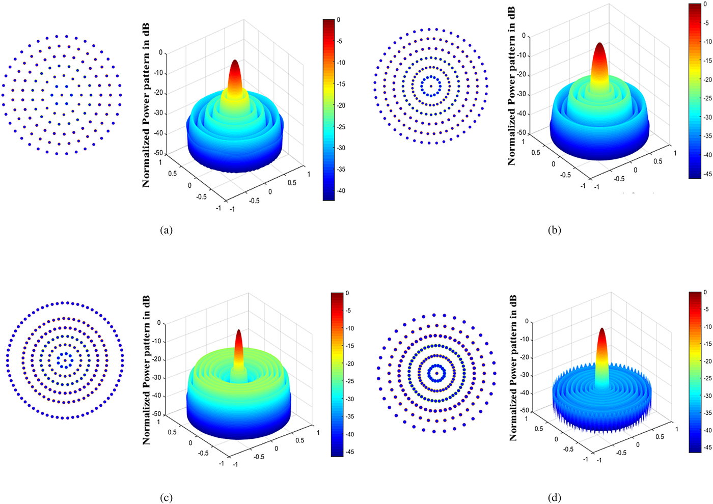
A uniform 6-ring CRA with isotropic antennas is considered here with a total number of 133 elements including the central element. The inter-element distance in each ring is fixed at 0.5λ. Each element in the ring has uniform excitation amplitude (i.e. I mn = 1). The ring radii are fixed at mλ/2. For such a uniform CRA, the SLL is found to be −16.71 dB whereas peak directivity and FNBW are obtained as 25.62 dB and 21.60° respectively. Figure 2(a) shows a uniform 6-ring CRA in the x–y plane and corresponding radiation pattern. Table 1 shows the SLL, FNBW, peak directivity, total number of uniformly excited array elements, ring radii, and number of array elements in each individual ring.

Fig. 2. Optimal array construction and corresponding power pattern for synthesized Multiple concentric ring array (MCRA). (a) Uniform 6-ring MCRA. (b) Synthesized MCRA using optimized d m using SOS for case 1. (c) Synthesized MCRA using optimized r m using MFO for case 2. (d) Synthesized MCRA using optimized d m and r m using CSA for case 3.
Table 1. Directivity (D), SLL, FNBW, total number of active elements (N), ring number (M), ring radii (r m), and number of active elements (N m) in each ring of a uniform 6-ring fully populated CRAA

Case 1: optimized inter-element spacing with fixed ring radii
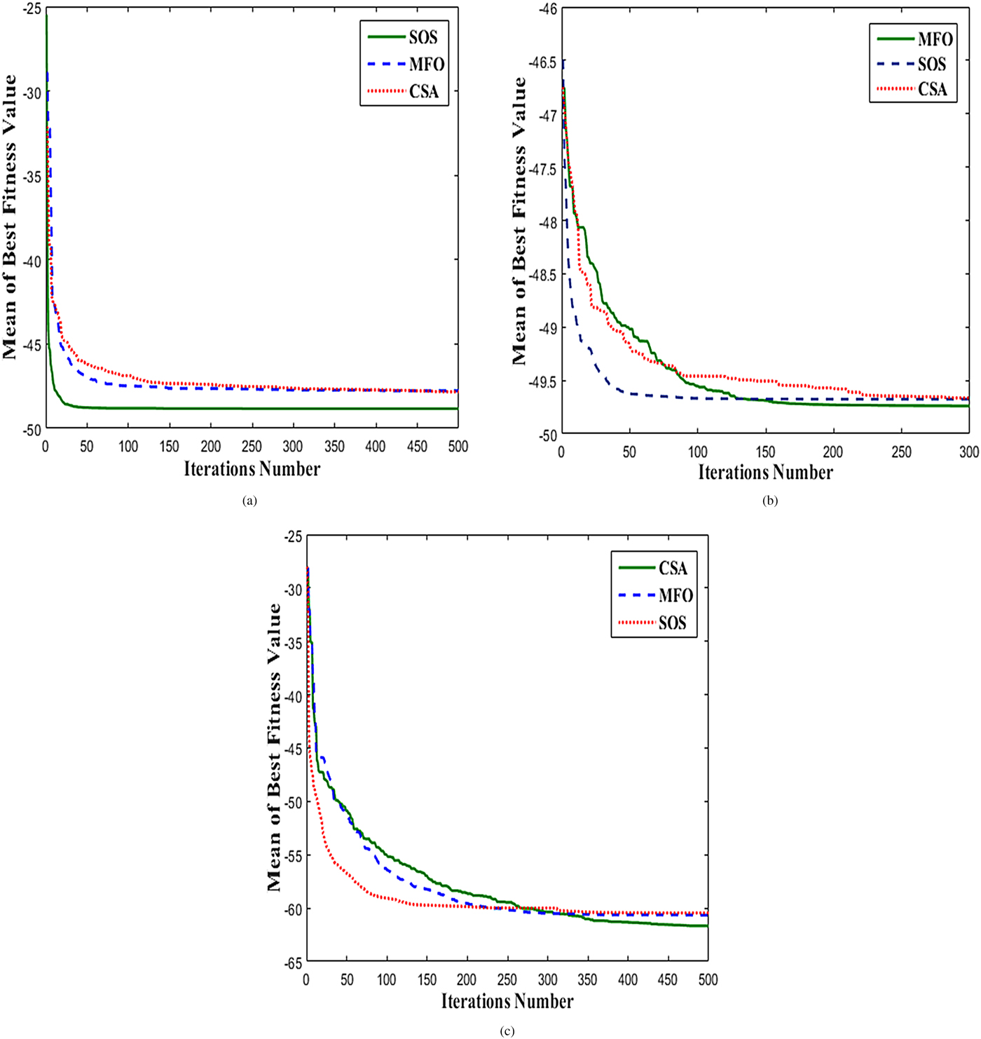
For the optimization of SLL and peak directivity, this approach is used where the ring radii are fixed at r m = m(λ/2) for mth ring and inter-element spacing (d m) is varied across each ring. Table 2 shows the overall results of SOS are comparatively better in terms of directivity and maximum reduced SLL than those obtained by CSA and MFO in this case. The optimal directivity and SLL obtained by SOS are 25.62 dB and − 23.21 dB respectively which is 6.50 dB lower than the SLL obtained for uniform array. SOS took computation time as long as about 5.53 h to give the optimal solution. Figure 2(b) shows the layout of the array with 212 elements and its corresponding radiation pattern obtained by SOS. The convergence curve for SOS, CSA, and MFO is demonstrated in Fig. 3(a).

Fig. 3. Convergence curves drawn between mean of best fitness value versus iterations number. (a) Convergence curve obtained in case 1 using CSA, MFO, and SOS. (b) Convergence curve obtained in case 2 using CSA, MFO, and SOS. (c) Convergence curve obtained in case 3 using CSA, MFO, and SOS.
Table 2. Directivity (D), SLL, FNBW, no. of variables (V), total number of active elements (N), ring number (M), inter-element spacing (d m), ring radii (r m), and number of active elements (N m) in each ring of a synthesized 6 CRAA for cases 1, 2, and 3

Case 2: optimized ring radii with fixed inter-element spacing
An alternative method to get peak directivity and maximum reduced SLL is optimizing the ring radii. The inter-element spacing in each ring is fixed at 0.5λ. A total number of five independent trials restricted to 300 iterations per trial have been used to reach upon the best solution. The fitness function converges in 300 iterations only. Therefore, further increasing the iteration number and number of trials will be time killing. In this case, there is marginal difference in the performance of all the three algorithms. CSA, MFO, and SOS offer almost equal directivity of about 27.88 dB with corresponding minimized SLL of −21.81, −21.97, and −21.89 dB and corresponding FNBW of 13.0°, 12.8°, and 12.8° respectively. The results obtained by MFO are considered to be compared with the results obtained by CSA and SOS in Table 2. This case illustrates that the performance of MFO leads SOS and CSA. The optimal directivity and minimized SLL in this case are better than the results obtained with uniform array. MFO required about 1.09 h reaching upon its optimal level. The resulting optimized array obtained by MFO with 221 array elements and corresponding power pattern is shown in Fig. 2(c). The convergence curve for SOS, CSA, and MFO is given in Fig. 3(b).
Case 3: optimizing the ring radii and inter-element spacing
This case is even a more effective approach toward achieving simultaneous optimization of SLL and directivity of uniformly excited CRAA. Optimizing the ring radii and inter-element spacing using CSA, MFO, and SOS yields excellent results. CSA gives an optimum directivity of 29.32 dB with minimized SLL of −32.69 dB. Meanwhile, MFO shows a nice robustness in the optimized results with directivity as high as 29.26 dB and SLL as minimized as about −32.76 dB. Apart from this, SOS also generates directivity of 29 dB with corresponding worst SLL of −33.22 dB. The corresponding FNBWs are 17.8°, 18.0°, and 18.8°, respectively. The results summary obtained by all the three algorithms is presented in Table 2. With CSA, the optimal directivity and optimal SLL obtained are 0.43 and 4.87 dB better than those obtained in [Reference Haupt18], respectively. These results are 0.14 and 3.66 dB better in terms of SLL and directivity as compared with [Reference Guo, Chen and Jiang19] as well. CSA took about 2.34 h to reach its optimal level. For MFO, the peak directivity and SLL are 0.37 and 4.94 dB improved in comparison with [Reference Haupt18] and 0.08 and 3.37 dB better than in [Reference Guo, Chen and Jiang19], respectively. Even the results of SOS are also considerable. It gives a more directivity of 0.11 dB and more minimized SLL of about 5.4 dB better as compared with [Reference Haupt18] and better directivity of 0.18 dB and more SLL of 4.19 dB as compared with [Reference Guo, Chen and Jiang19] as well.
Hence, it can be said that all the three proposed algorithms presented here have potential for synthesizing the uniformly excited ring array. In addition to this, directivity and SLL obtained by the three algorithms are far better than the previous two cases and also those obtained in case of uniform Circular concentric ring array (CCRA). The optimal array lay out and corresponding power pattern obtained by CSA is indicated in Fig. 2(d). The convergence curve in this case is shown in Fig. 3(c).
Figure 2 gives the array construction and corresponding power pattern obtained in each case with  $u_x = {\rm sin} \theta {\rm cos} \emptyset \; $ and
  $u_y = {\rm sin} \theta {\rm sin} \emptyset $. The investigation of all numerical results obtained by CSA, MFO, and SOS for cases 1, 2, and 3 are summarized in Table 2 with common parameters. Table 3 portrays the statistical data including best cost, mean value, standard deviation, and run time for CSA, MFO, and SOS for all the three cases considering the last iteration value of every run. Using uniform amplitude excitation, the designing problem in SOS require more optimization variables, hence, longer computation time for converging to a good solution is seen for SOS as compared with other two algorithms.
Table 3. Statistical data including best cost, mean value, standard deviation, and run time for cases 1, 2, and 3 considering the last iteration value of all five runs of each algorithm

Comparison of accuracies based on Wilcoxon rank sum test
Table 4 gives the p values and h values obtained from the Wilcoxon rank sum test for CSA and MFO with respect to SOS for cases 2 and 3. The test is done at 1% significance level considering the best iteration value of each of the five runs of each algorithm. In both cases, the h value is 0 which proves the failure to reject the null hypothesis at 1% significance level. Also, the p values obtained for SOS with respect to other algorithms are more than 0.01. Hence from the statistical analysis, it is clear that there is marginal difference in accuracies obtained by the three algorithms. In other words, once again it can be said that all the three algorithms are effective in delivering significant results in synthesizing uniform CRAs.
Table 4. h values and p values obtained from the Wilcoxon rank sum tests done at the 1% significance level for comparing SOS with CSA and MFO algorithms in cases 2 and 3 considering the last iteration value of each of the five runs of each algorithm

Conclusion
The synthesis of uniformly excited six CRAAs has been proposed in this work using the state-of-the-art meta-heuristic optimization algorithms such as CSA, MFO, and SOS. All the three proposed meta-heuristics are able to achieve good solutions in line with the objective of this work. This paper portrays manifold contributions: first, novel application of CSA, MFO, and SOS in the optimal synthesis of uniform multiple CRAs; second, from simulation results, it is clear that case 3 with variable inter-element spacing and ring radii outperforms cases 1 and 2; third, CSA, MFO, and SOS overtake the results obtained for uniform multiple CRAs and those obtained in [Reference Haupt18] and [Reference Guo, Chen and Jiang19] for peak directivity and maximum reduction in the SLL. The superior control over optimal directivity along with the optimization of SLLs makes this paper unique. The proposed optimal methods with statistical analysis using the Wilcoxon rank sum test validate the effectiveness of these proposed techniques in synthesizing the uniformly excited multiple CRAs. This can be also be used for the synthesis of other array configurations.
Acknowledgement
This work is an outcome of the R&D work undertaken under the Visvesvaraya Ph.D. Scheme of Ministry of Electronics & Information Technology, Government of India, being implemented by Digital India.
 Kailash Pati Dutta received a degree in B.Sc. Engineering (ECE) from the Vinoba Bhave University, Hazaribag in 2008 and M.Tech. from BIT Sindri, Dhanbad, India in 2012. Presently he is pursuing his Ph.D. in the Department of Electronics and Communication Engineering at the National Institute of Technology, Durgapur, India. His main research interests include optimization techniques, Array Antenna and Evolutionary Algorithms, and microwave devices.
 G. K. Mahanti was born in 1967 in West Bengal, India. He obtained his B.E. in Electronics & Communication Engineering from NIT, Durgapur, India; M.E. in Electronics System and Communication from NIT, Rourkela, India; and Ph.D. from the Dept. of Electronics and Electrical Communication Engineering, IIT, Kharagpur, India. He has more than 23 years of teaching and research experience. Presently he is working as a Professor, Department of Electronics and Communication Engineering, National Institute of Technology, Durgapur, India. He is a senior member of IEEE, USA. He has published approximately 80 papers in journals and in national and international conferences. He was the reviewer of many international journals such as Electronics Letter, IEEE Antennas and Wireless Propagation Letter, IEEE Transaction on Antenna and Propagation, Progress in Electromagnetics Research, IET Microwave, Antenna and Propagation, and many conferences. His biography is listed in Marqui's Who is Who in the world. His research area is Array antenna synthesis, Meta-heuristic optimization algorithms & Electromagnetics.