


Introduction
Microstrip antennas are widely used in mobile and satellite applications because of its beneficial features like lightweight, compact size, less expensive, and easy to be fabricated. Lots of fractal shaped antennas will be discussed. Fractal shaped antennas have some attractive features that stalk from their geometrical properties. A fractal geometry gives rise to increased current length leading to miniaturization because of its own scaled-down replica for increasing the perimeter of the given shape. An overview of fractal shape antennas has been proposed in [Reference Werner and Ganguly1], it shows the fractals have no characteristics size, and it contains many copies of themselves at different scales. Lots of researchers have discussed different shapes in fractal. Sierpinski fractal shape dual band Monopole antenna for LTE applications has been proposed in [Reference Lizzi and Massa2]. Several fractal shaped structures have been proposed for multiband antennas [Reference Bayatmaku, Lotfi, Azarmanesh and Soltani3–Reference Kumar and Nath5]. E-shaped fractal patch antenna is proposed in [Reference Bayatmaku, Lotfi, Azarmanesh and Soltani3], it is used to achieve the size reduction and increases the number of the operating band for mobile communication applications. H-tree fractal antenna using CPW feed for WLAN, WIMAX, RFID, C-band, Hiper LAN, and UWB applications is presented in [Reference Reha, Amri, Benhmammouch, Said, Ouadih and Bouchouirbat4]. Different shapes of the fractal are discussed in [Reference Kumar and Nath5]. A new koch-like sided fractal bow-tie dipole antenna has been proposed in [Reference Li and Mao6], it consists of a pair of isosceles triangles with Koch-like sides.
Lots of researchers in fractal shaped antennas without DGS have seen miniaturization, but by using defected ground structure (DGS), it has attained a lot of attraction by researchers for improving the lack of microstrip antenna like narrow bandwidth, low gain, and cross-polarized radiation [Reference Reddy and Vakula7–Reference Prajapati9]. To enhance the bandwidth, using Minkowski fractal shaped DGS has been reported in [Reference Reddy and Vakula7]. The two annular ring-shaped DGS with a circular patch has been explored in [Reference Kumar and Guha8] for cross-polarized radiation. The specific shape of the DGS in the ground layer of multi-layered circularly polarized microstrip antenna for enhancing the bandwidth is proposed in [Reference Prajapati9]. To reduce the mutual coupling between microstrip antenna elements by novel fractal DGS band-gap filter has been explored in [Reference Wei, Li, Wang, Xing and Xu10].
Circularly polarized microstrip antennas are widely used over linearly polarized due to its property of reducing the power loss caused by the misalignment between the transmitting and receiving antennas. Lots of single-feed circularly polarized microstrip antennas have been proposed [Reference Carver and Mink11–Reference Nasimuddin, Chen and Qing15]. Single feed circularly polarized microstrip antenna is commonly used because of its simplest design to achieve the CP radiation [Reference Carver and Mink11]. A single-feed circularly polarized microstrip antenna with an additional cross slot in the ground plane is proposed in [Reference Row and Ali12]. A new single-feed arrowhead-shape slotted circularly polarized micro strip antenna is proposed in [Reference Gautam, Kunwar and Kanaujia13]. The circular polarization radiation and reduction in antenna [Reference Gautam, Kunwar and Kanaujia13] size are achieved by placing an arrowhead-shaped slot in the first quadrant along the diagonal axis of a square patch. A compact single layer dual annular-ring patch with a cross-slot ground plane for CP is fabricated and experimentally verified is proposed in [Reference Bao and Ammann14]. New asymmetric-circular shaped slotted microstrip antennas using single feed with slits for CP and RFID applications are proposed in [Reference Nasimuddin, Chen and Qing15], for achieving CP radiation and reduction in antenna size, the asymmetric-circular shaped slots are embedded symmetrically along the diagonal axis of a square patch. Some circularly polarized slot antennas using coplanar waveguide feed and microstrip line feed have been discussed [Reference Patil, Singh, Kanaujia and Yadav16–Reference Patil, Singh, Kanaujia and Yadav19]. A novel design circularly polarized slot antenna for wideband is proposed in [Reference Patil, Singh, Kanaujia and Yadav16]. The circular polarization radiation of the presented antenna [Reference Patil, Singh, Kanaujia and Yadav16] is obtained by placing an inclined coupling slot-loaded feed line on the ground plane. A novel design of printed asymmetric wide slot circularly polarized antenna for the digital cellular system is presented in [Reference Singh, Patil, Kanaujia and Pandey17]. A compact dual band circularly polarized micro strip antenna has been proposed in [Reference Patil, Singh, Kanaujia and Yadav18]. The CP radiation of the presented antenna [Reference Singh, Patil, Kanaujia and Pandey17] is obtained by using a modified square ring slot in the ground plane. A low profile, dual band, dual sense circularly polarized wide slot antenna is proposed in [Reference Patil, Singh, Kanaujia and Yadav19]. The dual band and CP radiation of the designed antenna [Reference Patil, Singh, Kanaujia and Yadav19] are obtained by C shaped patch and wide square slot etched on the ground plane with two strips.
Lots of circularly polarized microstrip antennas using fractal shapes have been proposed in [Reference Rao and Sharma20–Reference Reddy25]. A circularly polarized single feed Minkowski fractal boundary microstrip antenna is proposed in [Reference Rao and Sharma20], it shows the good circular polarization by changing the fractal boundary dimension in both the directions of the antenna. A single-feed compact circularly polarized microstrip antenna has been proposed in [Reference Rao and Sharma21] using fractal curve boundary, due to its fractal curve as the boundary to the square patch shows the size reduction. This antenna achieved a return loss bandwidth of about 3.25% and 3-dB AR bandwidth of about 0.81%. A compact single-feed circularly polarized stack antenna consisting of Minkowski-island-based fractal patch with an aperture coupled design is proposed in [Reference Hung, Liu, Bor and Chen22], this fractal structure is able to generate dual mode and two orthogonal modes for circular polarization. A compact fractal boundary circularly polarized microstrip antenna has been proposed in [Reference Reddy and Sharma23], for achieving the CP radiation the sides of the square patch is replaced by asymmetrical prefractal curves. A new design of Koch fractal circularly polarized antenna based is proposed in [Reference Farswan, Gautam, Kanaujia and Rambabu24]. The CP radiation and reduction in the size of the designed antenna [Reference Farswan, Gautam, Kanaujia and Rambabu24] are obtained by introducing two asymmetric Koch fractal geometries on x- and y-plane of the square radiator. A single-feed circularly polarized Flared-U-type fractal boundary microstrip antenna has been presented in [Reference Reddy25]. By interchanging the edges of a square path [Reference Reddy25] with asymmetrical Flared-U-type fractal curves in two perpendicular directions, two degenerated orthogonal modes are generated for CP radiation. Several circularly polarized fractal slotted DGS microstrip antennas have been proposed [Reference Prajapati, Murty, Patnaik and Kartikeyan26–Reference Pandey, Pandey and Sarun28]. A compact circularly polarized micro strip antenna for mobile satellite application is proposed in [Reference Prajapati, Murty, Patnaik and Kartikeyan26], in this design two unequal lengths rectangular shaped slots, orthogonally to each other on the circular patch is able to generate the circular polarization. A novel technique to design circularly polarized single-feed microstrip antenna is proposed in [Reference Wei, Li, Wang, Xu and Xing27]. However, the CP radiation of this single-feed square patch microstrip antenna is achieved by etching the fractal DGS in the ground plane. New designs of the circularly polarized micro-strip antennas are proposed in [Reference Pandey, Pandey and Sarun28] based on tree fractal geometries. The excellent CP radiation with minimum AR is achieved by the parametric study of the fractal trees etched on the ground plane [Reference Pandey, Pandey and Sarun28].
A single-feed circularly polarized microstrip antenna with inclined E-shaped fractal DGS is proposed in this article. The CP radiation of a single feed antenna is obtained by placing an inclined E-shaped fractal slot along the diagonal axis of a ground plane while the patch remains intact. Due to this inclined E-shaped fractal on the ground plane, enhances the magnitude of the orthogonal component of the electric field of the linearly polarized antenna to the desired level with 90° phase difference for CP operation. An inclined E-shaped fractal slotted DGS in order to enhance the various properties of the proposed antenna. Due to the variation in the angle of the inclined fractal slotted DGS and patch slot length ls, a best quality CP performance is being obtained. The achieved impedance bandwidth for working band is 444 MHz (3.247–3.691 GHz) for VSWR<2 with 3-dB axial ratio bandwidth for the operating band is 87 MHz (3.583–3.67 GHz). The proposed antenna exists in the downlink range of CA-band (3.4–3.7 GHz) application and also come inside the band of FCC (3.1–10.6 GHz). It is mostly useful in satellite communication and mobile WIMAX operation (IEEE 802.16e-2005 standard). IEEE 802.16/WiMAX technology intends to provide broadband connectivity to both fixed and mobile users in a wireless metropolitan area network (WMAN) environment.
IFDGS geometry and antenna design
The design of a single layer and single feed third iterative inclined E-shape fractal slotted DGS E-shape patch antenna is shown in Fig. 1. The proposed antenna is fabricated on easily available FR4 substrate of thickness 1.6 mm (ɛr = 4.4, tan δ = 0.02) with a size of 41 mm × 41 mm × 1.6 mm. In the proposed paper, asymmetry in the design signifying to the fractal slot is embedded along the diagonal axis in the ground plane, which has different dimensions. Due to this inclined fractal slotted DGS, the two orthogonal modes are generated with equal amplitude and 90° phase difference for circularly polarized radiation. The DGS in the ground plane can be generally designed to obtain the CP operation by growing the magnitude of cross-polarization (XP) component of the electric field of the linearly polarized antenna.

Fig. 1. Geometry of the proposed antenna with the third iterative IFDGS; (a) top view, and (b) bottom view.
The geometry of E-shape fractal is created in an iterative form, give rise to self-similar structures. The stages of iterations of a fractal design in the ground plane are shown in Fig. 2. The first iteration of the proposed design is an original E-shape as shown in Fig. 2(a). Figure 2(a) shows the first iterative fractal shape can be achieved by cutting two solid rectangles in one of the main rectangle lengths. The second iterative fractal shape evolves from first iterative fractal. In such a way, the high-level iterative fractal structures of E-shape are obtained by subtracting smaller and smaller rectangles to the structures as shown in Fig. 2(b)–(c). 3k branches are generated in each stage of iteration of E-shape fractal, where k is the number of iterations. The proposed IFDGS circularly polarized antenna is fed using 50-Ω coaxial probe (feeding technique). The third iterative E-shaped IFDGS antenna has been finalized for obtaining the CP radiation with optimized IFDGS parameters as shown in Fig. 1. The top and bottom images of the fabricated antenna are shown in Fig. 3.

Fig. 2. Designed various stages of iteration of the inclined fractal-DGS; (a) first iteration, (b) second iteration, and (c) third iteration (proposed). l 1 = l 0/2, l 2 = l 1/2 or l 2 = l 0/4.

Fig. 3. Fabricated proposed antenna; (a) top view, and (b) bottom view.
Parametric study of the third iterative IFDGS
The third iterative E-shaped IFDGS structure was simulated using Ansoft HFSS electromagnetic software and mathematically examined. To show the circularly polarized generation mechanism, the parametric studies of the proposed antenna are being conducted. This antenna has the key parameters of IFDGS length ln, IFDGS angle θ, and patch slot length ls. In the parametric study, at a time only one parameter was varied, while the other parameters were kept constant. The optimized parameters of the proposed design are listed in Table 1.
Table 1. Proposed antenna dimensions.

Variation of IFDGS length ln
To obtain the circularly polarized radiation of the proposed antenna, an inclined fractal slotted DGS in the ground plane is to be used. Figure 4 shows the simulated results of antenna S 11 and axial ratio with the variation of the iterative length ln = l 0/2n, (n = 1, 2, 3). The value of IFDGS length l 0 varied from 1.5 to 2.5 mm in the step of 0.5 mm with the other parameters kept constant. As shown in Fig. 4, orthogonal modes are not found for l0 = 1.5 and 2.5 mm. The proposed antenna has two resonant modes as shown in Fig. 4. The fundamental mode is fixed along y-axis with resonant frequency 3.34 GHz due to constant E-shaped patch fed at y = 12 mm while the second mode is shifted to the right side with the length l 0 = 2 mm. When l 0 is increased from 1.5 to 2 mm, two orthogonal modes are generated. At IFDGS l 0 of 2 mm, the S 11 graph predicts the circular polarization as shown in Fig. 4(b). Figure 4 shows as the value of l 0 increases from 2 to 2.5 mm, the impedance bands are shifted to the left side. At IFDGS l 0 of 1.5 and 2.5 mm, the operating bands are resonated with linear polarization.
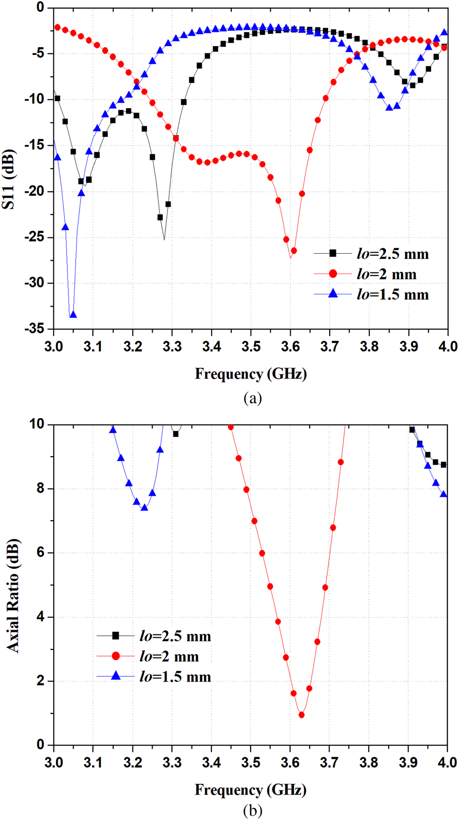
Fig. 4. Simulated S 11 and AR with varying IFDGS length l 0.
Variation of patch slot length ls
The antenna performance is also affected by patch slot length ls. The simulated results of antenna S 11 and axial ratio with the variation of the patch slot length ls are shown in Fig. 5. The value of ls varied from 2.6 to 3.6 mm. The operating band is resonated with linear polarization at the ls of 3.6 mm. After decreasing the patch slot length ls to 3.1 mm, the dual resonating modes generated a wideband with CP radiation of the proposed antenna. At ls of 2.6 mm, the impedance bandwidth remains unchanged but AR is not good. The best axial ratio of 0.95 is achieved at ls of 3.1 mm.
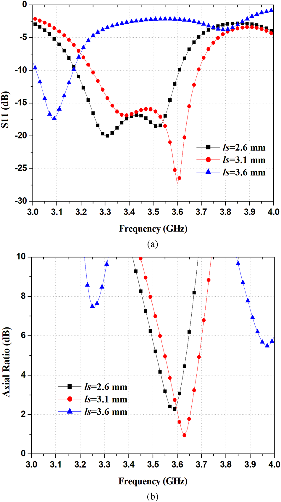
Fig. 5. Simulated S 11 and AR with varying patch slot length ls.
Variation of IFDGS angle θ
A third iterative E-shaped fractal slot with a θ inclination angle to the x-axis is introduced in the ground plane, which affects the performance of the antenna. The simulated S 11 and axial ratio with the variation of the IFDGS angle θ are shown in Fig. 6. The inclined angle θ was varied from 25° to 27°. The operating band is resonated with linear polarization at θ = 25°. After increasing the inclination angle of θ from 25° to 26°, the impedance bands shifted to the right side and dual resonating frequencies generated a wideband with CP radiation at 26°. For θ = 27°, both the return loss bandwidth and axial ratio are decayed. Finally, at θ = 26° the operating band is wide and CP achievement is good.

Fig. 6. Simulated S 11 and AR with varying IFDGS angle θ.
Results and discussion
To validate the simulated results, the standard photolithography process is used to fabricate the proposed structure in the laboratory prototype. The electrical performance of the proposed antenna such as return loss, axial ratio, and gain and radiation pattern are concluded by using AgilentTM vector network analyzer of N5230A: PNA-L series. It is the instrument to combine the functions of network analyzer, power meter and spectrum analyzer. The axial ratio of the proposed circularly polarized fractal DGS antenna is measured in an anechoic chamber. The antenna under test is mounted on the antenna positioner and is kept inside the anechoic chamber. The standard CP antenna is (dipole antenna) connected to port 2 of Vector Network Analyzer (VNA) and the AUT is connected to port 1 of VNA. After this arrangement, the transmitting antenna (connected to port 2 of VNA) is rotated over its axis and the minimum and maximum power received.
Return loss bandwidth
The E-shaped inclined fractal slotted DGS lying on the lower side of the substrate effects reactive loading. Due to the iterations of E-shaped IFDGS, the total electrical length to be increased with the same area, shows the good impedance matching. Table 2 shows, an improvement of return loss bandwidth with the successive iterations of inclined fractal slotted DGS antennas. The comparison of S 11 parameters of first, second, and third iterations are shown in Fig. 7. The comparison of simulated S 11 parameter (with and without third iterative IFDGS) and measured S 11 of the proposed antenna are shown in Fig. 8. The proposed antenna results without third iterative E-shaped IFDGS shows an impedance bandwidth (S 11 <−10 dB) of 90 MHz (from 3.30 to 3.39 GHz) at 3.34 GHz of center frequency while the impedance bandwidth with IFDGS is expanded to 444 MHz (from 3.247 to 3.691 GHz) at 3.47 GHz of center frequency, which is broader than the antenna without IFDGS. Due to the presence of dual resonating frequencies, the return loss bandwidth is wider. The IFDGS under the radiating patch responding reactive loading minimizes the quality factor of the antenna, because of this impedance bandwidth increases of the IFDGS antenna as compared to an antenna without IFDGS. It was noticed that the measured impedance bandwidth (S 11 <−10 dB) of the proposed antenna is about 12.7% (from 3.247 to 3.691 GHz) at 3.47 GHz of center frequency was obtained. Figure 8 shows some deviation between simulated and measured results, possibly because of measurement error and fabrication tolerance.

Fig. 7. Simulated S 11 for different iterations of IFDGS.

Fig. 8. Comparison of simulated S 11 (with and without the third iterative IFDGS) and measured S 11 of the CP proposed antenna.
Table 2. Comparison between iterations of inclined fractal DGS.

Axial ratio bandwidth
To achieve the CP radiation, the E-shaped fractal shaped DGS patch antenna has two right-angled modes of the electric field with equal magnitude and 90° phase difference between them. Due to feed the patch at a single point, these two right-angled modes are generated at some resonant frequency with the same magnitude. After the proposed inclined E-shaped fractal slotted DGS is placed along the diagonal axis of the ground plane, the electric field of one mode can lead by 45° while that of the other can lag by 45° resulting in a 90° phase difference required for circular polarization.
Figure 9 shows the comparisons of axial ratio with first, second, and third iterations. Figure 9 shows the circular polarization is obtained after embedding the second iteration of E-shaped IFDGS. Figure 10 shows the comparison of simulated axial ratio with and without the third iterative E-shaped IFDGS and measured axial ratio. It is noticed that the AR bandwidth is found to be better after embedding the third iterative IFDGS. The measured AR bandwidth (axial ratio <3 dB) of the proposed antenna is about 2.39% (from 3.583 to 3.67 GHz) with the center frequency of 3.626 GHz was achieved as shown in Fig. 10.

Fig. 9. Simulated axial ratio for different iterations of IFDGS.

Fig. 10. Simulated (with and without the third iterative IFDGS) and measured axial ratio of the CP proposed antenna.
Gain, front to back ratio (F/B) and radiation pattern
Figure 11 shows the graph of gain with the frequency for different iterations of E-shaped IFDGS according to the simulated result. Figure 12 shows the simulated (with and without the third iterative IFDGS) and measured gain of the proposed antenna. The maximum simulated gain of 7.75 dBi and measured gain of 8.1 dBi was achieved for the desired operating band of the proposed antenna. The maximum measured gain of 8.1 dBi and simulated gain of 7.75 dBi was achieved for the required operating band of the proposed antenna.

Fig. 11. Simulated gain for different iterations of IFDGS.

Fig. 12. Simulated (with and without the third iterative IFDGS) and measured gain of the CP proposed antenna.
For good performance of the antenna front to back ratio should be high. The front to back ratio of the proposed structure is shown in Fig. 13. Front to back ratio of the proposed antenna is 29 dB at the center frequency, because of its back radiation and back lobes are suppressed. Due to the good front to back ratio, gain increased and side lobe level reduced. The F/B ratio of the proposed antenna without IFDGS is 22 dB, it increases by 7 dB with IFDGS.

Fig. 13. Front to back ratio (with and without the third iterative IFDGS) of the CP proposed antenna.
The measured and simulated radiation patterns of the proposed antenna in E (ϕ = 0°) and H- plane (ϕ = 90°) at the operating frequency of 3.626 GHz are shown in Fig. 14(a) and (b), respectively. The proposed antenna can radiate the left-handed circularly polarized (LHCP) in the upper-half space at 3.626 GHz as shown in Fig. 14.

Fig. 14. Simulated and measured radiation pattern of the proposed antenna at 2.61 GHz in (a) E-plane and (b) H-plane.
Surface current distribution
The simulated vector surface current distribution on the radiating patch of the proposed antenna for different time instants of ωt = 0°, ωt = 90°, ωt = 180°, ωt = 270° at the operating frequency of 3.626 GHz is shown in Fig. 15. The simulated vector surface current distribution on the radiating patch for different time phase is shown in Fig. 15 to indicate the CP operation. Figure 16 shows the simulated current path on the ground for different iterations of IFDGS. The increment in effective electrical length with the increment in iterations of E-shaped IFDGS as shown in Fig. 16, shows the increment of the ground current path.

Fig. 15. Simulated surface current vector distribution on radiating patch of the proposed antenna at 3.626 GHz (a) ωt = 0°, (b) ωt = 90°, (c) ωt = 180°, and (d) ωt = 270°.

Fig. 16. Surface current vector distribution on the ground plane with IFDGS at ωt = 0°; (a) 1st iteration, (b) 2nd iteration, and (c) proposed 3rd iteration.
The comparison of all measured and simulated results that are shown in figures gives satisfactory matching between them. The simulated and measured result shows some discrepancy; this may be due to the effect of measurement errors and fabrication tolerance.
The proposed antenna performance has been compared with other fractal slotted circularly polarized microstrip antennas as shown in Table 3. The comparison of the previous fractal slotted circularly polarized microstrip antenna with proposed antenna is shown in Table 3. It can be seen from the table that the proposed antenna has overall good than the other previous reported work.
Table 3. Comparative study of circularly polarized microstrip antennas based on fractal DGS and fractal antenna.

Bold texts are showing proposed work.
Conclusion
Design of single feed, single layer E-shaped IFDGS circularly polarized micro strip antenna has been proposed in this article. The inclined E-shaped fractal structure on the lower side of the less expensive FR-4 substrate is able to generate CP radiation. In the proposed article, the third iterative E-shaped fractal slotted DGS circularly polarized antenna has better antenna performance as compared with the second iterative fractal slotted DGS. This antenna performance is good as compared with other fractal circularly polarized micro strip antennas. The E-shaped patch with the third iterative E-shaped IFDGS circularly polarized micro strip antenna are fabricated and measured. Parametric study verifies that the impedance bandwidth and AR bandwidth could readily be optimized by varying IFDGS length, patch slot length, IFDGS angle. All the required results achieved by simulation are well-matched with measured results. The proposed antenna analysis has good radiation properties with LHCP wave at required AR bandwidth. This antenna is suitable for mobile WIMAX operation, wireless communication in CA-band and FCC.
 Sonal Gupta received her B. E. degree in Electronics & Communication Engineering from RGPV, Bhopal, India, the M. Tech. degree in Digital Communication System from AKTU (formerly UPTU), Lucknow, India in 2010. She is currently pursuing her Ph.D. degree in Electronics Engineering from AKTU, Lucknow, India. Her research interests are microstrip antennas, slot antennas, circularly polarized microstrip antenna for wireless communications.
 Shilpee Patil received her Ph.D. degree in Electronics Engineering from AKTU (formerly UPTU), Lucknow, India in 2019, her Master of Technology Degree in Digital Communication from GGSIP University, Delhi, India, in 2009. She received her B.Tech degree in Electronics & communication engineering from AKTU, Lucknow, India. Shilpee Patil currently is working as an Associate Professor in the Department of Electronics & Communication Engineering in Noida Institute of Engineering & Technology, Greater Noida, India. She has more than 11 years of teaching & research experience. She has keen research interest in design and modeling of microstrip antenna, circularly polarized antenna, and slot antenna for wireless communications. She is a reviewer of several journals of international repute, i.e. Journal of Electromagnetic waves and Applications, Frequenz, International journal of Electronics letters. She has published many national and International Journals. She has attended various training programmes in the area of electronics & communication engineering.
 Dr. Chhaya Dalela, Associate Professor in Electronics Engg. Department, currently Head of Department of Instrumentation & Control Engineering at JSS Academy of Technical Education, Noida, received the B.Tech. degree in Electronics Engg. from H.B.T.I., Kanpur in 1995, M.Tech. in Digital Communication from U.P.T.U., Lucknow in 2006, and Ph.D. in channel characterization and modeling in 2012. Her areas of research interest are radio channel measurements and modeling for mobile and fixed communications, microwave propagation, radio wave propagation related to broadcasting, Cognitive Radio, Telecommunication network planning, etc. She has published about 45 research papers in national and international journals & conferences and also a reviewer for journals in this field e.g. IEEE Antenna and wireless propagation letters, etc. She was honored by AKTU University, on the occasion of AKTU Founder's Day celebration, on 26th July 2019 at AKTU Lucknow, for her contribution towards development, progress of University in field of technical education.
 Binod Kumar Kanaujia is working as Professor in the school of computational and integrative sciences, Jawaharlal Nehru University, New Delhi since August, 2016. Dr. Kanaujia had completed his B.Tech. in Electronics Engineering from KNIT, Sultanpur, India in 1994. He did his M.Tech. and Ph.D in 1998 and 2004; respectively from Department of Electronics Engineering, I.I.T. B.H.U., Varanasi, India. He has keen research interest in design and modeling of reconfigurable and circular polarized microstrip antenna. He has been credited to publish more than 150 research papers with more than 430 citations with h-index of 12 in peer-reviewed journals and conferences. He had successfully executed four research projects sponsored by several agencies of Government of India i.e. DRDO, DST, AICTE, and ISRO. He is a member of several academic and professional bodies i.e. IEEE, Institution of Engineers (India), Indian Society for Technical Education and Institute of Electronics and Telecommunication Engineers of India.


