


Introduction
For demanding industrial environment, wireless sensor network (WSN) [Reference Wang, Balasingham, Merrett and Tan1] is preferred due to the advantages of wireless technology and its growing reliability levels. In the application scenarios of WSN where continuous monitoring is required, nodes need to be powered by alternating current (AC) -mains supply. This approach defeats the main purpose of “wireless” technology. With this context, it is preferred to eliminate the last wire of WSN, “AC mains power line” [Reference Gomez, Lagadec, Magno and Benini2]. The best approach for the “true sense” wireless monitoring is the use of energy harvesting techniques to power the nodes [Reference Vullers and Van Schaijk3,Reference Piqueras, Blanc, Climent, Sánchez and Capella4], i.e. design of self-powered wireless sensor network [Reference Wu, Rüdiger and Yuce5]. Electrical power can be harvested from various other forms of energy such as kinetic, thermal, and radiation energy [Reference Clayton, Andrews and Lenarduzzi6]. Kinetic and thermal energy-based harvesting options are being explored extensively for industrial applications. In any plant, there are abundant sources of kinetic [Reference Silva7] and thermal energy [Reference Hunter, Lavrik, Datskos and Clayton8]. Radiation harvesting is a generic classification which covers harvesting from radio frequency (RF), solar radiation [Reference Gasulla, Penella and Lopez-Lapeña9], and ionizing radiation (gamma and neutron) [Reference Yoshida, Chen, Nozawa, Tanabe and Sugie10,Reference Liakos11]. In this paper, we have explored the RF energy harvesting domain. RF energy harvesting [Reference He, Cheng, Peng and Stüber12] has low power density [Reference Friis13], but it is omnipresent both in indoor and outdoor environment due to the growing wireless technology usage. Based on the application, it is easy to design and deploy a dedicated RF source and to intentionally transfer RF power in the required direction. But, the limitation is, the RF energy is not uniformly available throughout the source of coverage [Reference Visser and Vullers14]. Harvesting range can be improved either by transmitting high power or by designing highly efficient harvesting system. The best example of high power intentional RF transfer is the popular Microwave Power Transfer (MPT) technique [Reference Kai15]; it is used with Solar Power Satellite system [Reference Glaser16]. Disadvantage of high power RF transfer is adverse biological effects [Reference Gavan and Tapuchi17,18]. So, the only option left for enhancing RF harvesting range is to design an efficient RF harvesting system. The basic concept behind RF energy harvesting is to rectify the RF signal and generate DC [Reference Visser and Vullers14]. Antenna taps the RF energy and feeds to the rectifier; this configuration is referred to as rectenna [Reference Eddy19]. As the radiated RF energy propagates, it disperses in space and its power density drops. So a single rectenna is able to intercept very little energy governed by its effective antenna aperture. For such scenario, if power sampling area is increased, the intercepted power will increase. To achieve this, it is not feasible to use an antenna with a large aperture. The next option is to aggregate the power intercepted by the multiple numbers of rectenna. In this paper, we have mathematically justified our statement that multiple rectenna will enable us to generate maximum power. Using the combination of multiple rectenna, a rectenna panel needs to be designed. Rectenna panel-based RF harvesting inherently uses discrete sampling in the spatial domain; thus, a proper methodology is required for designing the panel. We have formulated the approach for designing an efficient rectenna panel. The primary criterion for panel design is to intercept the maximum RF power available at its location. This power maximization involves optimization of rectenna panel design parameters. By our mathematical modeling, we have formulated the criteria for rectenna spacing selection. Paper flow begins with an overview of research available in far-field RF energy harvesting in the section “Related Work”. Followed by this, rectenna panel design aspects have been covered in the section “Consideration for Rectenna Panel Design”. This section also discusses rectenna panel design parameters and their optimization. In the section “Results”, performance comparison for various grid designs has been covered. Validation of developed mathematical approach with existing work in literature is also part of this section. A brief conclusion and possible future improvements are given in the section “Conclusion”.
Related work
In the literature related to wireless power transfer, we have mostly observed that the focus of researchers is inclined towards rectenna design. In the previous works [Reference Sun20–Reference Marian, Vollaire, Verdier and Allard22], to enhance rectenna efficiency, authors have explored the options for rectifier design such as series & shunt diode based rectifiers, bridge rectifier, and voltage doubler rectifier. In the studies [Reference Mukherjee, Patel and Mukherjee23,Reference Mukherjee, Patel and Mukherjee24], authors have explored photonic band gap structure to enhance antenna performance. The authors of artifact [Reference Sinha, Killamsetty and Mukherjee25] have demonstrated that antenna gain and bandwidth improves with the usage of superstrate layer. Such efficient antenna designs when integrated with rectifiers will result in efficient rectenna design. To meet the growing demands of wireless power transfer, rectenna panel concept is being explored in various applications. Former researcher [Reference Shinohara and Matsumoto26], have designed a rectenna array and focused their study on identifying the rectenna connection configuration that results in highest output power. For their experimental analysis, the authors have arranged the rectenna in square grid. However, the work does not discuss the rectenna panel design parameters such as panel size, rectenna spacing, etc. A similar study [Reference Olgun, Chen and Volakis27] was carried out by researchers to analyze the effect of rectenna connection configurations (series, parallel, and cascade) on the panel generated power. The research work in [Reference Massa, Oliveri, Viani and Rocca28] provides the efficiency comparison for the two approaches used for designing the RF energy harvesting array namely, (i) rectenna array-based design and (ii) antenna array with a single rectifier-based design. Authors of work [Reference Marshall, Valenta and Durgin29] have quantified the peak available power for N 2 rectenna array. In their work, N is the number of rectenna in one row/column of the designed rectenna array; although, the criteria for its selection is not specified. In work [Reference Gretskih, Luchaninov, Gomozov, Penkin, Nesterenko and Katrich30] authors have implemented mathematical model to represent vast rectenna array as the single equivalent element of the rectenna. The developed model by researcher is useful for RF harvesting system performance characterization, although work does not discuss about rectenna panel design parameters. Rectenna panel design and development consist of rectenna design, rectenna connection configuration, and panel design parameters. All the aforementioned works do not discuss panel design parameters. With our extensive literature survey, we have come across three main research papers [Reference Otsuka, Omuro, Kakizaki and Soejima31–Reference Huang, Zhang, Chen, Huang and Liu33] which discusses panel design parameters. In work [Reference Otsuka, Omuro, Kakizaki and Soejima31], the author has focused on rectenna spacing optimization to enhance rectenna panel efficiency. Based on experimental study, the work concluded that rectenna panel efficiency degrades with increase of rectenna spacing beyond 0.77λ (λ is governed by operating frequency of rectenna). The study was performed for square grid rectenna pattern only. However, the result appears to be specific to the particular antenna chosen for rectenna, i.e. panel design. Researchers of artifact [Reference Strassner and Chang32] have designed honeycomb pattern rectenna panel with aperture overlap using circularly polarized rectenna. The work suggests that “little” aperture overlap eliminates the power voids, but authors have not quantified the percentage of overlap required. Authors of [Reference Huang, Zhang, Chen, Huang and Liu33] have designed a fixed size rectenna array with fixed rectenna spacing. For short distance harvesting equilateral triangle approach for rectenna placement with aperture overlap was proposed; but, criteria for rectenna spacing selection has not been mentioned by the researchers. Based on the type of antenna selected for rectenna panel design, authors might have selected the specified rectenna spacing for array design. Power captured by rectenna panel is analogous to the discrete sampling in spatial domain; thus, rectenna panel size, rectenna spacing, number of rectenna, and their arrangement pattern affects the efficiency of the overall RF energy harvesting system. For an efficient RF harvesting system design, aforementioned characteristics need to be studied and analyzed. In our paper, initially, we have focused on deriving the panel size for maximum utilization of transmitted RF power. Further, we have done extensive research on rectenna arrangement to study its effect on the rectenna panel performance. We have mathematically demonstrated that heterogeneous rectenna spacing eliminates rectenna overlap, and simultaneously results in maximum power interception with less number of rectenna. We have also done mathematical formulation for rectenna array dimension calculations and different types of rectenna arrangement patterns. In this work, we have utilized the knowledge gained from literature and proposed the best approach for rectenna panel design.
Consideration for rectenna panel design
The requirement of rectenna array
In general, as per RF radiation regulatory guidelines [34], it is not permitted to install or deploy any wireless device radiating RF power more than its operating frequency specified limits. With this aspect, RF power harvesting applications are mostly limited to near-field charging (wireless charging of mobiles). Even with the deployment of intentional RF source for RF energy harvesting, the far-field RF energy received at rectenna is very low. To practically use RF-based harvesting at distant locations the best approach will be to intercept the maximum transmitted RF power. To acquire RF power an efficient rectenna grid/panel need to be designed. The first condition for rectenna panel design is to identify the maximum limit for the panel dimension, beyond which there is no further scope of efficiency improvement in a particular scenario. Further, rectenna spacing, their number and arrangement pattern need to be optimized.
Maximum limit for rectenna panel dimension
If P t is the RF power transmitted (including transmit antenna gain) by an isotropic radiator, then based on Friis Law [Reference Friis13] RF power received, P r by rectenna panel at distance, R from the radiator will be given by equation 1.
 $$P_{r}=\left( {{A_{e}} \over {4 \pi R^{2}}}\right) P_{t}. $$
Here, A e is receiver antenna effective aperture. Considering equation 1, receiving antenna is only able to receive fractional part (A e/4πR 2) of energy being radiated by the transmitter. So the amount of unused power is calculated from equation 2
 $$P_{u i}=P_{t}\left(1- {{A_{e}} \over {4 \pi R^{2}}}\right). $$
Unused transmit power of an isotropic radiator, P ui in equation 2 can be made zero or near to zero only if antenna effective aperture is approximately equal to spherical wavefront area (A e ≈ 4πR 2) which is unrealizable or hypothetical for isotropic radiator case. For the scenarios, in which RF energy is being radiated ina particular direction, this situation is realizable as radiated RF wavefront will be of smaller size governed by RF source directivity (radiating antenna's solid angle). If the transmit antenna's solid angle (θHθV) governs its directivity; then, the maximum power radiated by the source will be focused in solid angle direction only [Reference Bansal35]. Here θH & θV are half power bandwidth of transmit antenna in horizontal and vertical plane, respectively. Then, received power,  $ P_{r\_d} $ and unused power,
  $P_{u\_d}$ for directional antenna case is given by equation 3 and 4.
 $$P_{r_{-} d}= {{A_{e}} \over {\theta_{H} \theta_{V} R^{2}}} P_{t}, $$
 $$P_{u_{-} d}=P_{t}\left(1- {{A_{e}} \over {\theta_{H} \theta_{V} R^{2}}}\right). $$
It appears that A e ≈ θHθV R 2 is realizable for directional antenna case. Maybe with a single antenna or rectenna, it will be difficult to conceptualize this; but, with rectenna array we can closely meet the zero unused power condition. If a rectenna panel of dimension L 2 with n × n rectenna is installed at a distance R, such that it covers the wavefront patch governed by directional antenna solid angle, then,  $ P_{u\_d} $ can be represented as shown in equation 5.
 $$P_{u, d}=P_{t}\left(1- {{\sum_{\,j=1}^{n} \sum_{i=1}^{n} (A_{e})_{i, j}} \over {\theta_{H} \theta_{V} R^{2}}}\right). $$
Here, we have assumed a square shape panel. Panel side length, L is equal to the diameter of the transmit antenna wavefront patch. Equation 5 will result in equation 6, if all the antennas are of the same type.
 $$P_{u_{-} d}=P_{t}\left(1- {{n^{2} A_{e}} \over {\theta_{H} \theta_{V} R^{2}}}\right), $$
 $${\rm If} \quad n^{2} A_{e}==\theta_{H} \theta_{V} R^{2} \quad {\rm then}, \quad P_{u_{d} d}=0. $$
Equation 7 explains that the maximum limit for the rectenna panel dimension is governed by the solid angle of RF energy source and panel placement distance from the RF source. The in-depth understanding of equation 7, reveals that rectenna should be efficiently arranged to minimize power voids (i.e.  $P_{u\_d}$) without aperture overlap.
Rectenna panel design parameters
Four main rectenna panel design parameters which will influence the performance of overall RF harvesting system are namely, (i) rectenna panel size (RPS), (ii) the number of rectenna, (iii) rectenna spacing, and (iv) rectenna panel design pattern. All these parameters are interconnected. Based on rectenna spacing and the number of rectenna in a row/column, RPS can be calculated. As per equation 6 and 7, rectenna panel should be designed to cover the full transmit antenna wavefront patch θ Hθ V R 2 (m 2) . Hence, rectenna panel size RPS, can be derived from the following equation (8).
 $${\rm Area}_{R P} = f\,(R P S) \geq \theta_{H} \theta_{V} R^{2}, $$
where AreaRP ≡ area of rectenna panel in m 2. If rectenna panel is of square shape, RPS is L × L, where L rectenna panel side is in meters. If n numbers of rectenna are placed with spacing d, then L can be calculated from equation 9.
 $$L= (n-1)d. $$
Based on equation 9 for a fixed panel size, if d reduces, n will increase and vice versa. So, the value of d should be appropriately chosen such that the maximum transmit power is intercepted with the minimum number of rectenna in a panel. As per equation 3, power received by rectenna is directly related to receiving antenna effective aperture A e. Similarly, the value of rectenna spacing, d is also coupled with A e. For any antenna other than single conductor type, A e is related to its physical aperture and gain by the relation shown in equation 10.
 $$A_{e}=e_{a} A_{\,p}= {{\lambda^{2}} \over {4 \pi}} G, $$
where A p: Antenna physical aperture e a: Antenna aperture efficiency λ: Wavelength in cm based on antenna operating frequency G: Antenna gain considering equation 10 and assuming A p as a circle (or if any other shapes) then its largest dimension d a can be approximated based on equation 11.
 $$d_{a} \approx {{\lambda} \over {\pi}} \sqrt{ {{G} \over {e_{a}}}}. $$
Generally, for single conductor type antenna such as a whip, dipole etc, antenna effective length, l e is specified. Based on l e antenna effective aperture is assumed as  ${l_{e}}^2$. Hence, in that case value of d a is not calculated from equation 11 as it is understood that it is l e. Thus, to eliminate aperture overlap in rectenna panel design, minimum horizontal and vertical spacing d, between two rectennas should be equal to or greater than d a.
 $$d \geq d_{a}. $$
Equation 12 condition will eliminate the physical overlap of antennas and will minimize coupling & overlap of the virtual reception zone of two antennas. Other than rectenna spacing parameter, the number of rectenna required for panel design is also affected by rectenna placement pattern. Fig. 1, displays four different grid patterns of the same dimension but with different rectenna spacing, number of rectenna, and rectenna arrangement pattern. All the grid patterns have been designed considering Grid-1 as the reference design. Horizontal and vertical rectenna spacing for the four grids is as follows:
Grid-1: Rectenna Spacing, d 1 = d
Grid-2: Rectenna Spacing, d 2 = d 1 with subgrid at distance d 1/2 from the main grid, i.e. triangulation arrangement of rectenna
Grid-3: Rectenna Spacing, d 3 < d 1
Grid-4: Rectenna Spacing, d 4 = d 1/2

Fig. 1. Rectenna placement pattern for panel design, (a) Grid-1 with rectenna spacing d 1, (d 1 equal to d a), (b) Grid-2 with the main and subgrid rectenna spacing as d 1. Subgrid placed at offset of d 1/2 from the main grid, (c) Grid -3 with rectenna spacing d 3, (d 3, less than d a), (d) Grid -4 with rectenna spacing d 4, (d 4 equal to d 1/2). In all grid patterns red and orange dots represent rectenna and yellow circle represents transmit antenna wavefront. Orange dots represent active rectenna, i.e. rectenna covered by the yellow circle, intercepts direct radiation from RF source.
In Fig. 1, all grids shown are square shape grids. Grid-1, 3, and 4 have the same pattern with different rectenna spacing. For Grid-2, rectenna spacing is the same as of Grid-1, but extra rectenna are added by incorporating a subgrid of smaller size with the same rectenna spacing as for the main grid. Grid-3 has been designed with Grid-1 pattern but has the same number of rectenna as used for Grid-2. To attain the mentioned configuration rectenna spacing has been reduced accordingly. Throughout the paper Grid-1 will be used as reference for calculations. For all grids, rectenna arrangement pattern will be discussed with reference to Grid-1. For illustration and derivation Grid-1 has been designed using 4 × 4 rectenna panel, but the calculation has been done for generic grid size n × n (for Grid-1). Figures in paper displaying various grid patterns has been designed for illustration with reference to 4 × 4 size Grid-1. Further, Grid-4 has also been designed with half of the rectenna spacing used for Grid-1; accordingly number of rectenna also scales up. Based on rectenna spacing and the type of pattern used, the total number of rectenna (TNR) used for panel design can be calculated from the following relations. For Grid-2, 3, and 4 number of rectenna in single row/column has been derived with reference to Grid-1 layout.For Grid-1: Number of rectenna in single row/column = n
 $$\therefore \quad TNR_{1}=n^{2}. $$
For Grid-2: Number of rectenna in single row/column = n Number of rectenna in subgrid single row/column = n − 1
 $$\therefore \quad TNR_{2}=n^{2}+(n-1)^{2}. $$
 For Grid-3: Number of rectenna in single row/column =  $ \sqrt {(n^{2}+(n-1)^{2})}$ As mentioned above rectenna spacing is reduced, so that total no of rectennas are same as used in Grid-2
 $$\therefore TNR_{3}=n^{2}+(n-1)^{2}. $$
For Grid-4: Number of rectenna in single row/column = 2n − 1
 $$\therefore TNR_{4}=(2 n-1)^{2}. $$
Figure 2, reveals that the total number of rectennas required for panel design varies significantly even for the same size panels if panels to be designed have different rectenna spacing and placement pattern.

Fig. 2. Total no of antennas required to design Panel of different grid structure with reference to Grid 1 design.
Rectenna panel utilization factor calculation and analysis for different Gridpatterns
As depicted in Fig. 1, four grid patterns namely Grid-1, Grid-2, Grid-3, and Grid-4 with varying degree of compactness has been analyzed. In the figure, red dots symbolize antenna; orange dots represent antennas intercepting maximum radiations in the area governed by the yellow circle. The transmitter antenna wavefront governed by its radiation direction solid angle is signified in yellow circle. For maximum interception of the power, the panel normal should be along the RF wave propagation, and antenna polarization should match with the transmit antenna polarization. As the pattern arrangement is different for all the Grids, the number of rectenna covering the transmit antenna wavefront is different. The rectenna covered by transmit antenna wavefront will actively contribute for RF harvesting while uncovered rectenna will harvest scattered or reflected RF power. Hence, Rectenna Panel Utilization Factor (RPUF) has been calculated for each type of panel design. The uncovered region of transmit antenna wavefront conveys about the amount of transmit power unused. RPUF is the ratio of the number of active rectenna to the total number of rectennas used for panel design. The rectenna covered by yellow circle area has been referred to as active antennas. Using diagrammatic view of grid designs, it can be interpreted that count of active rectenna is almost equal to total number of rectennas in the grid with one column less than the existing grid. Based on grid design, RPUF for Grid-1, Grid-2, Grid-3, and Grid-4 can be calculated as follows: Grid-1:
 $$R P U F_{1}= {{(n-2)^{2}+4} \over {n^{2}}}. $$
Grid-2:
 $$R P U F_{2}= {{(n-1)^{2}+(n-2)^{2}+4} \over {n^{2}+(n-1)^{2}}}. $$
Grid-3:
 $$R P U F_{2}= {{(n-1)^{2}+4} \over {n^{2}+(n-1)^{2}}}. $$
Grid-4:
 $$R P U F_{4}= {{(2 n-3)^{2}+4} \over {(2 n-1)^{2}}}. $$
For the equation 17–20 a factor of 4 has been added to account for the reception done by rectennas at the periphery of the panel. RPUF graph for all the four designed panels is shown in Fig. 3. It is observed that the RPUF of Grid-2 and Grid-4 are similar and superior compared to Grid-1 and 3 design. But comparison with respect to TNR metric (Figure 2) reveals that Grid-2 can achieve the same RPUF as for Grid-4 but with lesser number of total rectennas.

Fig. 3. Rectenna Panel Usage Factor for different grid structures with respect to Grid1 design.
Figure 3, elucidates that RPUF curve does not linearly increase with increase in number of rectenna. Compact rectenna arrangement pattern results in reduction of rectenna spacing. Concerns for reduced rectenna spacing are increase in rectenna aperture overlap, RPUF saturation and increase in number of rectenna. Practically and economically we cannot mount the large number of rectenna in one panel. Hence, with optimum placement approach (type of grid) optimum value of rectenna spacing d, should be chosen.
Optimization of rectenna spacing
For a panel of fixed size, increase of rectenna count in row/column will result in reduction of rectenna spacing. If equation 12 is violated, then chosen rectenna spacing will result in rectenna aperture overlap. This overlap will affect the individual rectenna RF reception capabilities. As per current grid pattern definitions, Grid-1 is designed with rectenna spacing d as d a; thus, it does not have rectenna aperture overlap. For Grid-3 and 4, certainly overlap exists as their rectenna spacing is less than non-overlap rectenna spacing. In case of Grid-2, as subgrid is placed at distance less than rectenna spacing, overlap is expected. Considering the equations 10–12 and grid pattern definitions, Grid-3 and Grid-4 merge to Grid-1 if rectenna spacing is increased to eliminate the overlap region. Scenario for Grid-2 is different as subgrid is placed at offset of distance d/2 from the main grid location. For Grid-2 overlap region will become zero if rectenna spacing is more than  $\sqrt {2}d_{a}$; although, with rectenna spacing of
  $\sqrt {2}d_{a}$ Grid-2 will result in the decrease of RPUF as the value of n will drop by
  $\approx \sqrt {2}$. In the Grid-2 pattern, with different rectenna spacing for horizontal and vertical rectenna arrangement unused power can be reduced without rectenna aperture overlap. As shown in Fig. 4, by equilateral triangulation approach rectenna arranged with spacing, d a will not have any overlap and also uncovered region will be low. For designing a grid with triangulation placement, the spacing between columns and rows should be d a and
  $\sqrt {3}d_{a}$ respectively for both the main grid and sub grid. The resultant arrangement will be tightly compact structure with negligible power voids. Figure 5 shows the comparison of Grid-1 and Grid-2 pattern with three type of rectenna spacing namely, (d a,d a) homo, (
 $\sqrt {2}d_{a}$,
 $\sqrt {2}d_{a}$) homo and (d a,
  $\sqrt {3}d_{a}$) hetero. We will refer the pattern formed with non-overlap spacing (
 $\sqrt {2}d_{a}$,
 $\sqrt {2}d_{a}$) as Grid-2_NO and pattern with heterogeneous spacing(d a,
 $\sqrt {3}d_{a}$) as Grid-2hetero.

Fig. 4. Equilateral Triangulation approach for rectenna panel design.

Fig. 5. Grid pattern comparison (a) Grid-1 with uniform rectenna spacing, d a (b) Grid-2 with equal rectenna spacing, d a (c) Grid-2_NO with equal non-overlap rectenna spacing,  $\sqrt {2}d_{a}$ (d) Grid-2hetero with non-uniform spacing d a and
  $\sqrt {3}d_{a}$.
Figure 5 emphasize that as the rectenna spacing changes, the number of rectenna used for Panel design also changes. The main visible advantage with Grid-2hetero is that scenario of no overlap with negligible transmit power wastage (non-intersecting region of transmit antenna wavefront with the rectenna aperture result in transmit power wastage) is feasible. The best comparative metric will be the evaluation of RPUF value for Grid-2_NO and Grid-2hetero. For Grid-2_NO (Figure 5(c)), TNR, and RPUF can be calculated using equations 21 and 22.
 $$TNR_{G_{-} 2NO}=n_{1}^{2} + (n_{1}-1)^{2}, $$
 $$RPUF_{G_{-}2NO}= {{(n_{1}-1)^{2}+(n_{1}-2)^{2}+4} \over {n_{1}^{2}+(n_{1}-1)^{2}}}, $$
where, n 1: Number of rectennas in single row/column of the main grid of Grid-2_NO. As for this grid, rectenna spacing is  $\sqrt {2}d_{a}$ so based on equation 9,
  $n_{1} = {n-1}/{\sqrt {2}} + 1$
 $$\therefore \quad R P U F_{G_{-2}, N O}= {{(n-1)^{2}-\sqrt{2}(n-1)+5} \over {(n-1)^{2}+\sqrt{2}(n-1)}}. $$
For Grid-2hetero (Figure 5(d)) TNR and RPUF can be calculated as follows: Number of columns in rectenna panel is same as Grid-2 with uniform spacing, d a = n. If there exist 2n 2 number of rows (including the main and sub grid) in rectenna panel then, based on vertical rectenna spacing of  $\sqrt {3}d_{a}$ and equation 9, n 2 can be calculated by equation 24.
 $$n_{2} = {{n-1} \over {\sqrt{3}}} +1. $$
 $$\eqalign{ \therefore \quad R P U F_{G_{{\rm hetero}}} &= {{(n_{2}-1) n+n_{2}(n-1)} \over {n_{2}(2 n-1)}} \cr &= {{(n-1)(2 n+1+\sqrt{3})} \over {(n-1+\sqrt{3})(2 n-1)}}. } $$
Figure 6, shows the comparison of RPUF of all the variants of Grid-2 design based on rectenna spacing and Fig. 7 presents the comparison for the TNR required for Grid-2 design variants. From these figures, following three inferences can be made: (i) RPUF of Grid-2 with overlap and non-overlap configuration is almost the same. Hence, with overlap configuration more rectenna is required to design the panel of the same size. (ii) Grid-2hetero based on equilateral triangulation approach results in maximum utilization of rectenna (highest RPUF). (iii) The number of rectenna required for panel design is the least for non-overlap configuration of Grid-2.

Fig. 6. Rectenna panel Utilization Factor Comparison for Grid-2 (with rectenna spacing d a), Grid-2_NO and Grid-2hetero.

Fig. 7. Comparison of the total number of rectenna required for Grid-2 (with rectenna spacing d a,), Grid-2_NO and Grid-2hetero pattern to design panel of varying size.
Optimization of number of rectenna for Grid-2hetero pattern
It can be observed from Fig. 5 that corner rectenna does not contribute for RF energy harvesting; so, un-utilized rectenna should be eliminated to reduce design cost. Other aspect is for equilateral triangulation-based rectenna panel design, un-utilized rectenna count varies with rectenna size. Hence, some methodology is required to identify and quantify the un-utilized rectenna. Equation 9 gives information regarding maximum number of columns required for the main grid and sub gird are n and n−1, respectively. Based on the value of n and n 2 (required for Grid-2hetero), the number of rows in the main grid, M R and rows in sub grid, M R also need to be optimized to minimize the count of un-utilized rectenna. Value of M R and S R can be calculated using Algorithm 1.
Algorithm 1
1) M R = rounddown(n 2), value of n 2 calculated from equation 24. Here, rounddown() is a function which rounds the number down.
2) Calculate the length of Rectenna using the following two relations,
 $L_{M1} = \sqrt {3}n_{2}$ and $L_{M2} = \sqrt {3}(n_{2}-1)$
3) If (L − L M1) > (L − L M2) then, S R = n 2 − 1 else S R = n 2 + 1. Here, L is length of rectenna calculated from equation 9.

Based on Algorithm 1, the number of rows in subgrid can be more than the main grid. Accordingly, for Grid_2hetero TNR can be calculated using following equation 26.
 $$ T N R=n \times M_{R}+(n-1) \times S_{R}+K. $$
In equation 26, K is a factor governed by the number of un-utilized rectennas removed and additional rectenna added to improve the rectenna panel performance. Value of K can be calculated from Algorithm 2. Grid_2hetero design for four different value of n is shown in Fig. 8. In the Fig. 8, the circles with no fill (in the main and sub grid) symbolizes the unutilized rectenna. The rectenna indicated with blue color are additional rectenna required to utilize the dispersed RF signal from wavefront edge. It was observed that for the case when value of M R is even, there is a need to add two extra rectenna for better diagonal coverage of wavefront. Rearrangement of rectenna and elimination of un-utilized rectenna converts the square type grid to a hexagonal grid.

Fig. 8. Rectenna arrangement in Grid-2hetero pattern for four different values of n, (a) n is 4, M R is even and lesser than S R, (Case 2), (b) n is 5, M R is odd and greater than S R, (Case 3), (c) n is 6, M R is odd and lesser than S R (Case 4) and (d) n is 7, M R is even and greater than S R, (Case 1).
Algorithm 2
• Case 1: If M R is even and greater than S R then
(27)$$\eqalign{ K=2-\sum_{i=1}^{{(M_{R}-2)}/{2}} i \,\times \,&4-\sum_{i=1}^{{(M_{R}-2)}/{2}-1} i \times 4 \cr &=-M_{R}^{2}+4 M_{R}-2. } $$• Case 2: If M R is even and lesser than S R then
(28)$$K=2-\sum_{i=1}^{{(M_{R}-2)}/{2}} i \times 4 \times 2=-M_{R}^{2}+2 M_{R}+2. $$• Case 3: If M R is odd and greater than S R then
(29)$$\eqalign{ K=-\sum_{i=1}^{{(M_{R}-1)}/{2}} i \, \times \, & 4-\sum_{i=1}^{{(M_{R}-1)}/{2}-1} i \times 4 \cr & = -M_{R}^{2}+2 M_{R}-1. } $$• Case 4: If M R is odd and lesser than S R then
(30)$$K=-\sum_{i=1}^{{(M_{R}-1)}/{2}} i \times 4 \times 2=-M_{R}^{2}+1. $$


Number of active rectenna for Grid-2hetero will be different for each case based on the value of M R,S R and K. As RPUF is directly proportional to active rectenna count, its value for the mentioned cases can be calculated using the following equations.
Case 1:
 $$ R P U F= {{n+1+ (M_{R}-2)(2 n-1)+K} \over {T N R}}. $$
Case 2:
 $$ R P U F= {{3 n-1+ (M_{R}-2)(2 n-1)+K} \over {T N R}}. $$
Case 3:
 $$ R P U F= {{n+ (M_{R}-1)(2 n-1)+K} \over {T N R}}. $$
Case 4:
 $$ R P U F= {{3 n-2 + (M_{R}-1)(2 n-1)+K} \over {T N R}}. $$
The RPUF graph for optimized Grid_2hetero is shown in Fig. 9. It is observed that for odd number of rows in the main Grid_2hetero, it attains maximum value of RPUF, 1, i.e. value of unused power will be almost zero.

Fig. 9. RPUF for Optimized Grid_2hetero design.
Results
The Table 1 summarizes the rectenna panel design parameters for various grid configurations discussed in this paper. Based on this, TNR and RPUF comparison plots are displayed in Figs 10 and 11, respectively. Comparison of Grid-3 and Grid-4 has been omitted as they are the compact version of Grid-1. From the tabulated formulas and TNR & RPUF plot it can be observed that optimized Grid_2hetero with hexagonal shape is able to attain the highest RPUF value with the least number of rectenna. As observed by theoretical calculation hexagonal grid designed with the placement of rectenna in equilateral triangulation attains RPUF value of 1 (for odd number of rows in the main grid). Thus, it is certain that the panel designed with optimized Grid-2hetero layout will have maximum RPUF value in comparison to the panel designed with any other configuration.
Table 1. Rectenna panel design parameters comparison for various gridconfigurations used in our work


Fig. 10. TNR value comparison for various Grid Configurations.
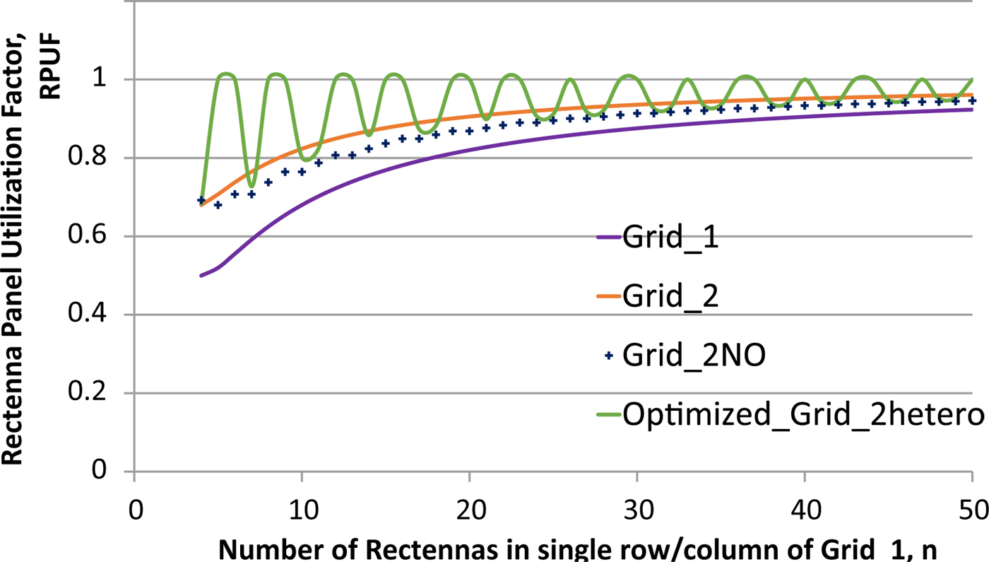
Fig. 11. RPUF Comparison for various Grid Configurations.
Validation of rectenna panel design approach
As discussed in the section “Related Work”, to the best of our knowledge detailed analysis on optimization of rectenna panel design parameters is not available in the literature. In work [Reference Otsuka, Omuro, Kakizaki and Soejima31], the author has done analysis on optimizing rectenna spacing. Researchers of [Reference Strassner and Chang32] have designed panel by arranging rectenna in a honeycomb pattern with aperture overlap. Similarly, authors of [Reference Huang, Zhang, Chen, Huang and Liu33], have designed rectenna panel with aperture overlap and fixed rectenna spacing of λ/2. For design validation, as shown in Table 2 we have done a detailed comparison of our analysis with abovementioned works. Square grid pattern used by [Reference Otsuka, Omuro, Kakizaki and Soejima31] matches with our work Grid-1 design. Authors of this paper have experimentally verified that if rectenna spacing is more than 0.7λ than the rectenna panel efficiency degrades. The equation 11, presented in our paper for calculating optimum rectenna spacing abides by their experimental result s. Similarly, the honeycomb panel pattern with aperture overlap used by authors in [Reference Strassner and Chang32] is comparable to Grid-2 layout in our work. However, they have designed a bigger size grid; it consists of 2n + 1 more rectenna than our Grid-2 design. Compared to existing panel designs, in our analysis, we have encompassed the aperture efficiency factor of antenna used for rectenna design. The effective aperture consideration eliminates the need for designing a bigger size panel. TNR for panel developed in [Reference Strassner and Chang32,Reference Huang, Zhang, Chen, Huang and Liu33] was not mentioned implicitly in their research work. Based on their design approach, TNR value for both the references has been deduced. With the above analogy, we can validate that the mathematical formulation developed by us can be used to design rectenna panel of any size. Moreover, our proposed optimized design, Grid-2hetero is optimal from existing designs used in the literature concerning the total number of rectenna, rectenna utilization and power void elimination.
Table 2. Comparison with existing rectenna panel design work available in the literature

Conclusion
The paper presents a detailed methodology for rectenna panel design. Rectenna panels are required to compensate the RF propagation losses by intercepting the maximum transmit power distributed in space. We have created the theoretical base which will aid in finalizing the rectenna panel design parameters such as panel size, number of rectenna, rectenna arrangement pattern, and rectenna spacing. We have theoretically demonstrated that the hexagonal shape rectenna panel designed with equilateral triangulation approach and minimum spacing between rectenna as governed by effective rectenna aperture will have the least number of rectenna but the highest value of RPUF, i.e. less unused power. Our mathematical approach for rectenna design has also been validated by comparing the rectenna design parameters with the practically designed and developed rectenna panel described in the literature. Over the existing approach for rectenna design, we have proposed the methodology which results in optimized, efficient rectenna panel design with minimum void without aperture overlap. To experimentally validate our proposed optimized design the rectenna panel will be fabricated and integrated with existing WSN deployments in our campus. The practical deployment will enable us to monitor rectenna panel performance round the clock. Overall, it will allow us to unveil the potential of RF energy harvesting.
Author ORCIDs
Vinita Daiya, 0000-0002-6192-3541
Acknowledgments
The authors gratefully acknowledge the constant support and motivation provided by Dr. B. K. PANIGRAHI and Dr. B.P.C. RAO, Senior Professors of Homi Bhabha National Institute, Indira Gandhi Centre for Atomic Research, Kalapkkam, Tamilnadu, India
 Vinita Daiya was born in Rajasthan, India, in 1986. She completed her B.E. in ECE and joined Indira Gandhi Centre for Atomic Research (IGCAR) Department of Atomic Energy, Kalpakkam in 2009 as Scientific Officer. She completed her M.Tech. in Wireless sensor Networking from Homi Bhabha National Institute (HBNI). Currently, she is pursuing her Ph.D. from HBNI. Her area of interest are RF signal processing, RF harvesting, antenna & rectenna design, physical layer security, and low power design for Wireless Sensor Network.
 Jemimah Ebenezer completed her B.E. degree in Electronics & Communication Engineering from Madurai Kamaraj University in 1993. She joined IGCAR in 1996 as Scientific Officer. She has done her M.Tech. in Computer Science in 2007 at IITM, Chennai. Currently, she is head of Simulator and Wireless Networking Section at IGCAR and leading a team of engineers.Under her guidance, significant advancement in the design & development of industrial grade EMI/EMC, environmental and seismic qualified WSN nodes and deployment of WSN for nuclear reactor applications were accomplished in IGCAR.
 R. Jehadeesan completed his engineering graduation in Computer Science and Engg. from Madras University in 1993. He acquired the post-graduate qualification of M.S. (Software Systems) with distinction from BITS, Pilani. He joined Indira Gandhi Centre for Atomic Research (IGCAR), Department of Atomic Energy, Kalpakkam in 1996. Presently, he is heading Computing Division and leading the IT teams working in the areas of High-performance computing, Data communication & Information security, Computational Intelligence Systems, Simulator, Wireless Sensor Networks, and Knowledge Management.


