NOMENCLATURE
- AR
aspect ratio
- Bo
buoyancy number
- C p
specific heat capacity
- d h
hydraulic diameter
- e
rib height
- e/d h
blockage ratio
- MUSCL
Monotonic Upwind Scheme for Conservation Laws
- Nu
Nusselt number
- Re
Reynolds number
- Ro
rotational number
- T ref
reference temperature
- T w
wall temperature
- U 0
inlet mean velocity
1.0 INTRODUCTION
The continuous efforts for improving efficiency and thermal performance in modern aero-engines lead to the use of very high turbine entry temperatures and to minimise the amount of coolant flow consumption. Therefore, highly sophisticated cooling techniques are essential to maintain gas turbine safety and durability under such extreme conditions. In order to increase the heat transfer performance of internal cooling systems, complex internal cooling channels are cast in the blades. Further enhancement is obtained by using of artificial roughness elements or turbulence promoters such as ribs, pin-fins or dimples.
There are many parameters affecting the performance of rib-roughened channels. For instance, the aspect ratio and orientation of the channel can vary within a wide range depending on the location of the channels inside the turbine blade. This influence has been discussed by Dutta and Han( Reference Dutta and Han 3 ), Han and Chen( Reference Han and Chen 6 ) and Liou et al.( Reference Liou, Chang, Chen, Yang and Lan 12 ). Rib installation inside the channel such as the orientation, spacing or blockage ratio also has significant impacts on the flow passing through the channel and, therefore, the heat transfer enhancement. Besides, since turbine rotor blades rotate at very high rotation speed, the coolant flow passing through internal channels experiences Coriolis forces and centrifugal buoyancy forces. These forces induce secondary flows and vortexes in transverse direction along the channel resulting in very complex flow-fields. In a ribbed channel, Coriolis forces interact with the separated flow promoted by a variety of turbulent devices producing a large diversity of secondary flows, that characterise their corresponding heat transfer performance. As a result, the interaction of the secondary flow induced by rotation and the rib turbulators results in heat transfer patterns different from stationary channels. According to a considerable amount literature, a mutual understanding is that the rotational effects will enhance heat transfer performance on pressure side, whereas it will reduce it on suction side in an orthogonal rotating channel( Reference Griffith, Al-Hadhrami and Han 4 , Reference Liu, Wright, Fu and Han 13 ). These geometrical and rotational effects been devoted to evaluating heat transfer characteristics in a vast number of experimental and numerical investigations over passed 40 years. Overall reviews of the background and advances in this field can be found in Han and Zhang( Reference Han and Zhang 7 ) and Ligrani( Reference Ligrani 11 ).
Additionally, wall-heating conditions may also have impact on heat transfer performance in rotating channels. In real turbine rotor blades, due to the characteristics of main annulus flow, pressure side and suction side of turbine blade experience different thermal loads. Therefore, this uneven wall-heating effect has to be considered in the design process to minimise thermal stress. In addition, in experimental setups, it is common to heat only one wall when optical access is involved( Reference Coletti, Jacono, Cresci and Arts 2 , Reference Mayo, Lahalle, Gori and Arts 15 , Reference Rau, Cakan, Moeller and Arts 18 ) due to measurement considerations. An in-depth discussion of this kind of set-up can be found in Coletti et al.( Reference Coletti, Jacono, Cresci and Arts 2 ).
It appears that not many researches have addressed these issues, only little literature( Reference Han 5 , Reference Hsieh and Liu 8 , Reference Parsons, Je-Chin and Yuming 17 , Reference Zhang, Han, Parsons and Lee 23 ) on the effect of heating one or more of the channel walls at different levels exists. It was found that the actual impact on heat transfer level was significant. They presumed that the impact was due to the Coriolis-induced cross stream secondary flows, which altered the local coolant temperature by carrying hotter or cooler fluid towards the leading or trailing wall. However, there is a lack of discussion in the references. This uneven heating condition also creates an unbalanced buoyancy force between the leading and trailing walls, which in turn may alters the flow behaviour as well as the heat transfer when rotating at high Buoyancy numbers. Because of the difficulties associated with simultaneous flow and heat transfer measurements, it is still unclear if the changes of the heat transfer are also due to the alteration of the flow-field. Therefore, it is necessary to systematically study this complex flow and heat transfer behaviour with the help of numerical methods.
The objective of present paper is to numerically investigate the impact of uneven wall-heating conditions on the internal flow and heat transfer performance of a 45° rib roughened rotating channel. Our earlier study with only one wall-heated case showed reasonable agreement against experimental data( Reference Wang, Quintanal and Corral 21 ). However, an uncommon behaviour was consistently observed by both, numerical simulation and experiment data. The heat transfer on trailing wall was reversely affected by rotation in a radially outward flow channel. We conjecture that uneven heating plays an important role, since most of studies associated with 45° inclined rib channels consider that all the walls are heated.
2.0 ROTATING CHANNEL MODEL
The testing geometry was designed by SNECMA based on a real HPT rotor blade two-pass internal cooling channel. It consists of two rectangular channels connected by a 180° sharp turn. The overall dimensions of the test channel can be found in Fig. 1. The total length of the channel is 350mm, and the height is 70mm. The width of the upstream and downstream passages is 31mm and 38mm, respectively. The gap between the two channels is 7mm and the distance between the divider wall and the outer end wall is 30mm. The outward upstream passage has an aspect ratio of AR = 1:2.25 and, after the turn, the inward downstream passage has an aspect ratio AR = 1:1.85. One side of the two channels is equipped with 45° square cross-sectional skewed rib turbulators, with a rib spacing P/e = 6 and a blockage ratio e/d h = 0.116, where the hydraulic diameter is referred to the upstream passage. In total, 14 ribs are arranged in parallel, while the other side remains smooth in order to ease the optical access to the infrared cameras. Details of experimental set-up can be found in Wang et al.( Reference Wang, Quintanal and Corral 21 ).
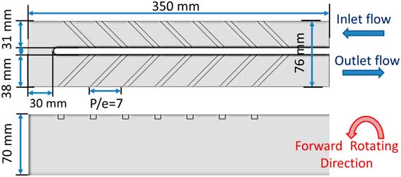
Figure 1 Cooling channel sketch.
3.0 NUMERICAL SET-UP
Previous studies( Reference Huh, Lei, Liu and Han 9 , Reference Wright, Fu and Han 22 ) have shown that the entry shape can have a significant impact on the flow-field and heat transfer performance. Therefore, the computational domain was extended to include the supply system in order to account for inlet entry effects. Figure 3 shows the computational domain and mesh used in the numerical simulations. The inlet/outlet supply system has a circular pipe shape that transitions to a C-shaped pipe near the joint with the transition pipe. The model is discretised by means of unstructured hybrid grids using an in-house mesh generator( Reference Wang, Corral and Chedevergne 20 ). The grid consists of a near-wall prismatic layer region, while the rest of the domain is discretised using isotropic tetrahedral elements. In total, 18 prismatic layers are constructed with y +<1 for all the tested Reynolds numbers. The total grid size is 13.5 million cells. A sensitivity study was performed with a 8 million cell model, and the change in the section averaged heat transfer coefficient was less than 3%. Hence, the solution obtained in current study is considered grid independent.
Steady-state simulations have been conducted using an in-house RANS code named as Mu 2 s 2 T ( Reference Burgos, Contreras and Corral 1 ). The code solves the 3D RANS equations using an edge-based data structure to spatially discretise the equations using a MUSCL scheme( Reference Luo, Baum and Lohner 14 ). Low Mach preconditioning is used to enhance the convergence and accuracy for low Mach number flows. The code is fully parallelised using MPI and executed on GPUs to improve computational efficiency.
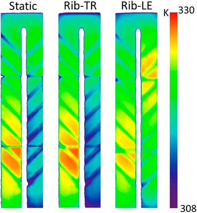
Turbulence effects were accounted for using the k−ω SST turbulence model( Reference Menter 16 ) with an inlet turbulence intensity of 5%. The inlet/outlet boundary conditions have been obtained from experimental measurements. Temperature and mass flow rate are provided at the inlet, and static pressure is set at the outlet. The wall temperature distribution at the ribbed wall was measured by an infrared camera system installed at ONERA, and used as boundary condition in the simulations (see Fig. 2). This numerical study was performed at Reynolds number Re=15,000 under three rotating conditions: stationary (Ro=0); forward rotation direction (Ro=0.3), where the ribbed surface behaves as the trailing wall (pressure side) of a rotor blade; and backward rotation direction (Ro=−0.3), where the ribbed surface behaves as leading wall (suction side) (Fig. 3).

Figure 2 Measured wall temperature distribution at Re = 15,000.
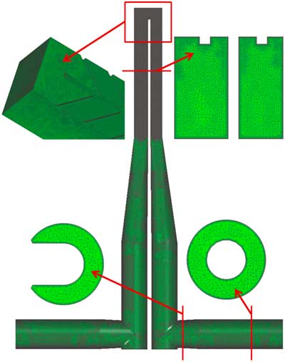
Figure 3 Hybrid mesh of computational domain.
In order to investigate the effect of wall-heating conditions, three wall boundary conditions were tested: (a) single ribbed wall heated, (b) all walls heated and (c) adiabatic. The mean buoyancy number, Bo is about 0.17 in cases (a) and (b), as in experiment. Both the rotation and buoyancy numbers are engine representative; however, the difference between the wall and the fluid temperature, T w and T ref, respectively, used in the experiments is between 5K and 6K, much lower than in engine relevant conditions. The supply system is set as adiabatic in all cases. A sketch of the overall boundary conditions can be found in Fig. 4.
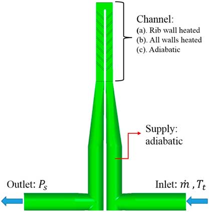
Figure 4 CFD boundary condition set-up.
4.0 RESULTS
For the sake of clarity, hereby we only consider the wall-heating effect in the first pass where rotating Coriolis and buoyancy effects are more conspicuous. For the flow domain investigation, the third segment of the first pass was chosen, since it is hardly affected by bend and entrance. The regions of interest and segment notation are illustrated in Fig. 5.
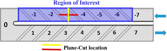
Figure 5 Segment index notation.
4.1 Segment averaged heat transfer validation
The numerical results were validated using the experimental data at the nominal condition. The comparison of the normalised segment averaged Nusselt number based on the smooth area between ribs is presented. The convective heat transfer coefficient in the simulations was computed as
 $${{h{\equals}q} \mathord{\left/ {\vphantom {{h{\equals}q} {\left( {T_{w} {\minus}T_{{ref}} } \right)}}} \right. \kern-\nulldelimiterspace} {\left( {T_{\rm w} {\minus}T_{{\rm ref}} } \right)}}$$
where the local reference temperature, T ref, is calculated based on the conservation of mean energy, in the same way, as it was performed in the post-processing of the experimental data:
 $$T_{{\rm ref,s}} {\equals}T_{{\rm in}} {\plus}s{Q \over {\dot{m}C_{p} }},$$
here T
in is the inlet temperature of the channel inlet, Q the total heat in a given section or segment,
 $\dot{m}$
the mass-flow rate and s ∈[0,1] stands for the curvilinear coordinate of the current location along the centre line of the channel.
$\dot{m}$
the mass-flow rate and s ∈[0,1] stands for the curvilinear coordinate of the current location along the centre line of the channel.
In order to validate the numerical results, the normalised segment averaged Nusselt number based on the smooth area between ribs is presented.
The segment index notation is illustrated in Fig. 13 and the Nusselt number is normalised with the Dittus–Boelter correlation( Reference Kays, Crawford and Weigand 10 ), Nu0. Figure 6 shows the comparison between experimental and numerical results for the single-ribbed heated wall (case (a)). In the upstream passage, the segment averaged heat transfer data are well predicted, both for the stationary and the ribbed surface rotating as the trailing wall (Rib-TR) cases. When the ribbed surface acts as the leading wall (Rib-LE), the numerical results over-predict the detrimental effect of the rotation on the heat transfer rate in the first passage, underestimating the heat transfer in overall by about 30–40% when compared with the experimental data. This is because the rotation stabilises the fluid at leading wall and enlarges the separation region, especially when the wall is heated( Reference Coletti, Jacono, Cresci and Arts 2 ). In this case, the massive separation of the flow leads to a bad prediction of the RANS codes which are not specifically tailored to this type of flows. In the bend region, the heat transfer efficiency was over-predicted in all the numerical simulations. This may be due to the fact that the k−ω SST model does not perform well in the presence of impingement flow and large separation areas. In the downstream passage, the overall heat transfer performance is reduced because of the flow is slowed down by the increase of channel area. In the stationary case, the numerical simulation under-predicts the heat transfer by about 15–20%, but the trend with the rib index is properly captured. The Rib-TR case gives a good overall agreement. Experimental data show that in the second passage, the impact of the sense of rotation in the heat transfer coefficient is quite small, leading to a similar heat transfer levels in the two rotating cases.
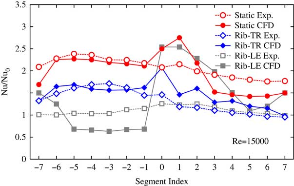
Figure 6 Normalised segment averaged Nusselt number. Filled symbols: CFD. Opaque symbols: experiments.
The most interesting result is that on the contrary than in previous works( Reference Huh, Lei, Liu and Han 9 , Reference Viswanathan and Tafti 19 ), the heat transfer efficiency drops, in the ribbed trailing wall (Rib-TR) case, compared with the stationary case. This behaviour is consistent, both in the experiments and in the numerical simulations. Moreover the magnitude of the drop in the upstream passage of Rib-TR case is large, being about 25%. This variation is much larger than the uncertainties that could be reasonably associated to either the experimental or numerical techniques used in here and, therefore, are believed to be due to a physical phenomenon.
4.2 Wall-heating effect on heat transfer distribution
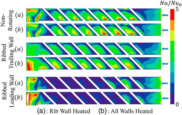
For the sake of clarity, hereby we only consider the wall-heating effect in the first pass, where the Coriolis and buoyancy effects are more clearly seen. Figure 7 shows the contour plots of the normalised Nusselt number distributions obtained from the numerical simulations for different heating conditions. In the absence of rotation, it is shown that the effect on the heat transfer rate of heating a single wall (cases (a)) or all the walls (case (b)) is fairly small, indicating that the flow field is essentially the same for both heating conditions.

Figure 7 Numerical results of Nu/Nu0 distribution for different wall-heating conditions.
For the ribbed trailing wall rotating test, case (b) has a significantly higher heat transfer at the wall than case (a). The overall patterns are similar, but the peak regions in case (b) are enlarged and displaced slightly downstream compared with case (a). This suggests that the main flow features in the vicinity of the ribbed wall have not been substantially changed. However, the reattachment point and the absolute heat transfer level have been modified and should be further investigated.
For the ribbed leading wall rotating test, very low heat transfer rates are observed in both cases. It can be conjectured that large recirculation bubbles dominate the inter-rib regions in both cases. However, it is not possible to deduce the flow behaviour from the heat transfer pattern since this is quite low.
4.3 Secondary flow characteristics
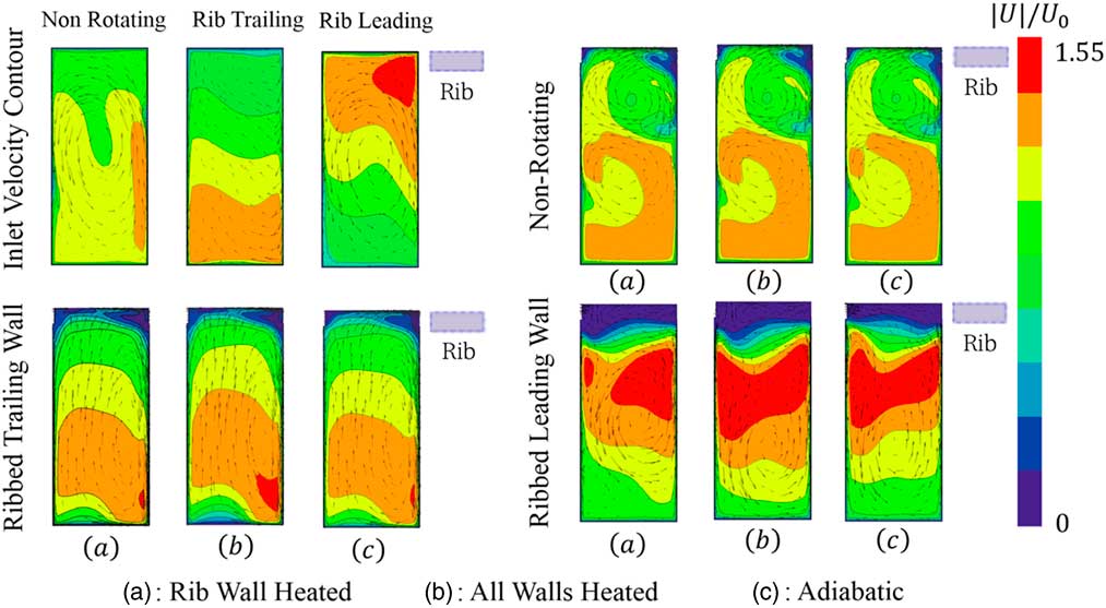
In order to enhance the understanding and further analysis of this complex flow-field, the secondary flows and velocity patterns in the channel are presented. Figure 8 displays the relative velocity contours and secondary flow features at the channel inlet, and at the middle of segment no. −3 (yellow line in Fig. 5). The relative velocity is normalised with the mean inlet velocity, U 0. The inlet velocity contours show that the entry geometry formed a counter clock-wise secondary flow at the middle of the channel in the non-rotating case. This secondary flow is weaken in rib trailing wall case, whereas it is preserved in rib leading wall case due to the interaction with the Coriolis induced secondary flow. It is clearly seen that under the action of rotation, the inlet velocity profiles are significantly altered with respect the non-rotating case. However, the entry flow profiles are identical for all the heating conditions, since there is no heating in the air supply system.

Figure 8 Span-wise inlet velocity and secondary flow features for different wall-heating conditions.
In the non-rotating case, the presence of inclined ribs (upper side) induces a span-wise high momentum flow along the rib creating a strong clockwise vortex in the vicinity of the ribbed wall. Unlike the straight rib channel, in which the heat transfer is mainly dependent on the separation-reattaching stream-wise flow, this span-wise motion strongly affects the heat transfer behaviour by aggressively increasing the flow velocity, and bringing cooler fluid to the rib wall. Meanwhile, the entry shape formed counter clockwise vortex is pushed to the lower part of the channel. It is observed that the flow field in this case remains unchanged for different wall-heating conditions, because of the heat is effectively convected downstream in this case.
In the ribbed trailing wall tests, rotation induces a secondary flow which moves fluid from the leading surface (bottom) to the trailing surface (top) of the channel. At the side wall, where the fluid is moving slow, the pressure gradient creates flow with the opposite sense, from upper side to lower side, to close the vortex. Figure 8 shows that the secondary flow patterns are essentially the same; however, there are significant changes in the velocity field. Compared with the rib wall-heated case (case (a)), the velocity is skewed towards the upper ribbed trailing wall when all the walls are heated (case (b)); therefore, a higher velocity is observed in the vicinity of the ribbed wall regions. In addition, a reduced velocity appears at the leading wall in case (b) compared with cases (a) and (c). This is because, when a wall is heated, near wall regions have lower density than the mean flow due to the temperature variation. Therefore, the buoyancy force acts in opposite direction to the stream-wise flow. As a result, this hotter flow will be slow down, and the cooler flow will be accelerated to keep mass continuity. This can be clearly seen at leading wall in case (b), compared with cases (a) and (c).
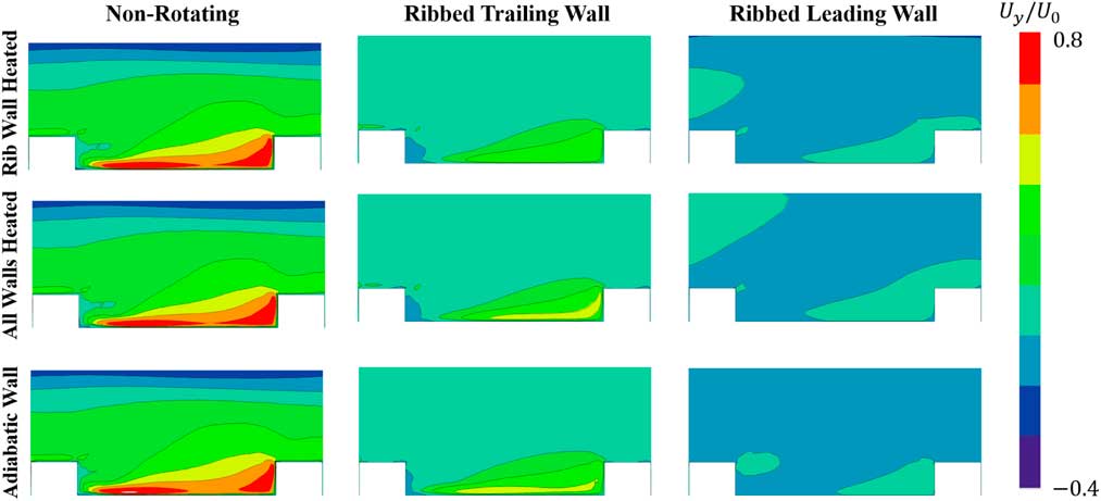
In the ribbed leading wall tests, very low velocity regions appears in the vicinity of ribbed wall (see Fig. 9), suggesting that the heat transfer level is much lower than in the non-rotating and ribbed trailing wall tests. The secondary flow shows similar patterns for different wall-heating conditions, moving fluid from the leading side to trailing side and back to leading side along the side wall. The presence of the central vortex is due to the interaction of secondary flow induced by the Coriolis force and the entry shape.

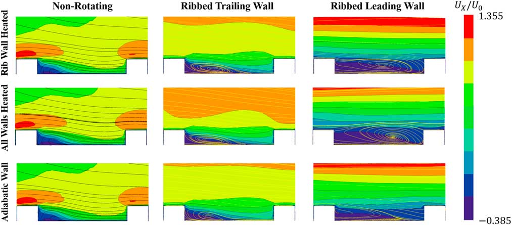
Figure 9 Stream-wise velocity contours and streamlines in inter-rib region for different wall-heating conditions.
The ribbed leading wall case exhibits the opposite behaviour compared with ribbed trailing wall due to the change of the rotating direction. The velocity profile in the all wall-heated case (case (b)) was shifted towards the bottom (smooth trailing surface) under the same effect of the buoyancy force analysed above.
4.4 Inter-rib flow characteristics
The impact of wall-heating conditions in the vicinity of ribbed wall can be investigated by analysing inter-rib flow field. Figures 9 and 10 display the stream-wise and span-wise velocities at the inter-rib region for different wall-heating conditions at the middle of segment number −3 (red line in Fig. 5). The main characteristics of the flow in the non-rotating channel is that the flow accelerates on the top of the rib due to the blockage of the cross section area, then a sudden expansion and the creation of a recirculation bubble with low momentum fluid are created. The recirculation bubble height is lowed due to the mixing with high momentum fluid of the core near the rib region. In addition, it is worth to notice that in the non-rotating tests, the magnitude of span-wise velocity induced by the inclined ribs is very high. It induces mixing that in turn promotes a faster re-attachment in the inter-rib recirculation region, and, therefore, high heat transfer can be expected. Similarly as analysed in the previous subsection, wall-heating conditions have very little impact on the flow-field in the non-rotating case.

Figure 10 Span-wise velocity contours and streamlines of span-wise inter-rib flow-field for different wall-heating conditions.
In the ribbed trailing wall tests, it can be observed that different heating conditions alter the flow-field more significantly. In the adiabatic case, the recirculation bubble re-attaches faster than in the two heated cases (see Fig. 9). The re-attaching was contributed by the destabilising effect of rotation, which enhances the entrainment of fluid from the recirculation bubble to the main flow, as well as the rib induced span-wise flow. However, because of the Coriolis induced and rib induced secondary flow are acting in the opposite direction, the interaction reduces the magnitude of span-wise flow compared with that of the non-rotating tests, resulting in a larger separation area.
When the ribbed wall is heated, the adjacent fluid experiences a centripetal buoyancy force in the upstream direction. This phenomenon can be explained by the schematic model shown in Fig. 11. Because of the heating, the recirculation region behind the rib has a higher temperature than the core flow; therefore, the rotating buoyancy force acts in the opposite direction of the stream-wise flow. Thus, the recirculation area is enlarged in the two heated cases compared with the adiabatic case. However, when all walls are under heating, due to the fact that leading wall has a lower heat transfer rate than the trailing wall, the fluid is hotter and the density lower than in the mainstream. As a result, the flow near the leading wall experiences a higher buoyancy force than the trailing wall (in Fig. 11). By the contribution of unbalanced buoyancy forces, the flow velocity near leading surface is slow down and pushed toward to the trailing surface. This flow motion enhances the mixing with the separation bubble by increasing the momentum of near wall fluid and the Coriolis effect. As a consequence, as shown in Fig. 9, the size of recirculation bubble in the all wall-heated case is slightly reduced compared with that of the ribbed wall-heated case.
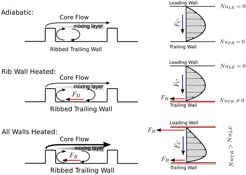
Figure 11 Schematic model of flow in ribbed trailing wall tests, under Coriolis and buoyancy forces.
When the ribbed wall behaves as leading wall, the shear layer generated by the rib is stabilised by the rotation and the entrainment of fluid from the separation bubble to the main stream is strongly reduced, resulting in an much larger recirculation area. When ribbed wall is heated, the recirculation bubble is further enlarged by buoyancy forces in both stream-wise and wall normal directions that occupy the whole inter-rib regions. Very low momentum fluid in both the stream wise and span-wise directions leads to a very low heat transfer as shown in Fig. 7.
4.5 Overall flow field and heat transfer characteristics
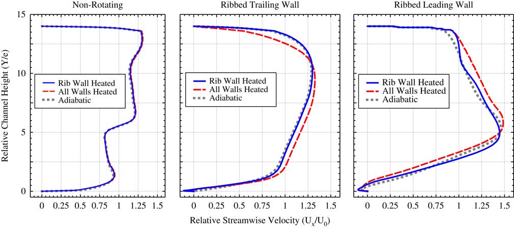
The stream-wise velocity profile along the channel height is presented in Fig. 12. The channel height is normalised with the height of the rib. It can be seen that due to the entry shape and the asymmetry of the channel, the stream-wise velocity in non-rotating tests does not show a typical channel flow profile. It is hence confirmed again that wall-heating conditions do not alter the overall flow field in non-rotating cases.

Figure 12 Relative stream-wise velocity profile along channel height at middle plane of segment −3 for different wall-heating conditions.
Figure 12 shows a reduction in the separation bubble length of the adiabatic case compared with that of the two heated cases, as explained in previous subsection, in the ribbed trailing wall case. The stream-wise flow near the leading surface (top) in the all-wall-heated case is strongly reduced , and the fluid core is pushed towards to the ribbed trailing wall (bottom). Also, the comparison between rib wall-heated case and adiabatic case suggests that the variation of stream-wise velocity is local when only the trailing wall is heated.
Figure 12 shows as well that in the ribbed leading wall case there is a shift of fluid towards the trailing side (top) when all the wall are heated due to the presence of buoyancy forces. In addition, the flow in the vicinity of the trailing wall (top) shows similar contours under the three heating conditions, confirming the finding that the impact of the buoyancy is smaller in the trailing wall than in the leading wall.
The overall heat transfer performance of the entire first passage is summarised in Fig. 13. It is shown that in the ribbed trailing wall cases, the heat transfer level is significantly higher in the all wall-heated case than in the single rib wall-heated case. The flow domain investigation confirms that this variation is mainly due to the centripetal buoyancy effect, which alters the flow profile inside the channel by reducing the velocity at the leading wall and pushing the fluid core towards the trailing wall. This behaviour enhances the heat transfer by bringing to the ribbed trailing wall cold, high momentum fluid, as well as increasing the strength of the Coriolis effect. In the ribbed leading wall case, the overall heat transfer rate is slightly lower in all walls heated case than in rib-only-wall heated. This is possibly because in the ribbed leading wall case, the secondary flow also brings hot fluid back to the leading surface alongside walls, therefore, increasing the local temperature and enlarging the buoyancy effect. However, since the heat transfer level is low, the variation is not as significant as in trailing wall tests.
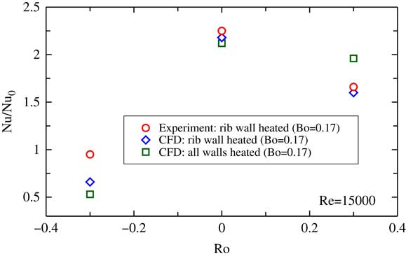
Figure 13 Overall normalised Nusselt number for different wall-heating conditions: CFD vs. EXP.
5.0 CONCLUSIONS
This paper investigates the impact of the wall-heating conditions on the heat transfer performance of a rotating channel with one side smooth and one side roughened by 45° inclined ribs. RANS simulations were conducted under three different wall-heating conditions in the present study: ribbed wall heated, all walls heated and adiabatic conditions. Numerical results have shown that uneven wall-heating conditions have negligible impact on the non-rotating case; however, large impacts, both in the heat transfer and flow-field, can be seen under rotation. The heat transfer level is significantly higher in the all wall-heated case than in the only ribbed wall-heated case, when the ribbed wall is in the trailing surface, and slightly reduced when the ribbed wall is in the leading surface.
The flow-field investigation shows that this variation is mainly due to rotating buoyancy effect. In rotating cases, uneven heating induces different buoyancy effects on the trailing and the leading wall, which alter the velocity profile of the main flow. As a consequence, also secondary flows and heat transfer performance are affected. When only one wall is heated, the buoyancy only alters the flow in the vicinity of heated wall, and the trailing surface is significantly less affected than the leading surface.
According to the results obtained in the paper, we conclude that when buoyancy effects are relevant, the heating settings can play a significant role in the heat transfer mechanisms and, therefore, in the experimental and numerical results.
ACKNOWLEDGEMENTS
The research leading to these results has received funding from the European Union Seventh Framework Programme (FP7/2007-2013) under Grant agreement no. 233799 (ERICKA). The authors wish to thank Industria de Turbopropulsores S.A.U. (ITP Aero) for its technical support and computing resources. The ERICKA consortium and members, in particular ITP Aero, ONERA and SNECMA, are greatly acknowledged for allowing the authors to publish this paper.