


I. INTRODUCTION
The growing demand of high data rate or high carrier frequency in wireless communications requires the development of ultra-wide band (UWB) systems that are able to transmit high bit rate over a wide frequency spectrum for short distances (<50 m). The optical domain can be used to solve many problems such as short transmission distances and expensive regenerating equipments [Reference Hur, Nam, Lee, Hwang, Oh and Jeong1, Reference Kim, Kang, Chung and Choi2], and to minimize the electro-magnetic fields exposure. Commercially available standard single mode fibers (SMFs) made from glass (silica) have optical attenuation losses below 0.2 and 0.5 dB/km in the 1550 and the 1300 nm windows, respectively. These losses are much lower than those encountered in free space or through transmission lines, e.g., coaxial cables. Therefore, by transmitting high-frequency microwave signals in optical fibers, transmission distances are increased significantly and the required transmission powers reduced greatly.
Radio-over-fiber (RoF) technology entails the use of optical fiber links to distribute RF signals from a central office to remote antenna unit. Combining the techniques of radio and fiber systems, it can reduce the complexity and cost of remote base stations, while providing large transmission capacity, high bit rate, low attenuation loss, and immunity to radio frequency interferences [Reference Seeds3].
RoF techniques are attractive for broadband wireless applications such as wireless local area network (WLAN), digital multimedia broadcasting, intelligent transport systems, and thus offer the flexibility of radio access [Reference Kitayama4, Reference Loyez5]. Optical generation and transmission of microwave and millimetre-wave signals at frequencies exceeding 60 GHz are one of the main challenges in developing hybrid optical wireless systems [Reference Kurniawan, Nirmalathas, Lim, Novak and Waterhouse6]. Furthermore, the high oxygen absorption in this range of frequencies gives us a large frequency reuse factor but also implies a small cell size for a wireless network.
There are several optical techniques for generating and transmitting microwave signals optically. RoF techniques may be grouped into three categories, namely intensity modulation-direct detection (IM-DD), remote heterodyne detection based on optical beating of two optical waves [Reference Kuri and Kitayama7], and harmonic up-conversion techniques [Reference Cabon and Nguyen8, Reference Le Guennec and Gary9].
IM-DD is the simplest method with a lowest based equipment cost for optically distributing RF signals. The RF signal directly modulates the intensity of the laser source and a direct photodetection is used for recovering it. There are two common ways to modulate the laser source [Reference Sricham, Rangsee and Worasucheep10]. In the first one, the RF signal directly modulates the laser driving current (direct modulation). In the second one, the laser works in continuous wave mode and an external modulator, such as a Mach-Zehnder modulator (MZM) or an electro-absorption modulator (EAM), modulates the intensity of the light. The direct modulation of a laser is limited in frequency, not only by the intrinsic bandwidth of the laser diode, but also by its biased circuit too; consequently, modulation frequencies cannot reach the mm-wave band. External modulators present various advantages for a photonic link such as a high bandwidth and a lower nonlinear distortion due to the optical frequency chirping commonly impacting a direct modulation of laser diodes. Since the introduction of the relatively cheaper EAM [Reference Lim11], there has been considerable interest in the use of EAMs as transmitters in fiber-optical systems [Reference Hur, Nam, Lee, Hwang, Oh and Jeong1, Reference Sricham, Rangsee and Worasucheep10, Reference Yamanaka, Fukano and Saitoh12]. These devices have replaced the MZM for transmitting optical wireless signal over fiber links because they have the advantages of both a lower cost and a lower biased voltage than MZM [Reference Prosyk13]. Therefore, EAM is chosen in our study.
This paper describes a modeling technique of an EAM integrated with a distributed-feedback laser diode (DFB LD). This model could easily evaluate the behavior of an optical transmitter implemented in the future hybrid optical radio systems. When introducing nonlinear models of standard SMF and PIN photodiode (PD), this specific design modeling can simulate a complete transmission link of fiber UWB radio systems. These developed equivalent large signal models of optoelectronic devices, implemented in advanced design system (ADS) at the circuit level, are used by ADS-Ptolemy to calculate, at the system level, the digital performances transmission of an RoF link using an external optical modulation when transmitting an UWB-orthogonal frequency division multiplexing (OFDM) signal.
II. Electro-absorption modulated Laser MODELING
EAMs are getting more and more attractive for use in both analog and digital high-speed optical communication systems [Reference Sricham, Rangsee and Worasucheep10] because of their low chirp, low driving voltage, low power consumption, compactness, and strong potential for monolithic integration [Reference Kim, Kang, Chung and Choi2, Reference Lim11, Reference Prosyk13]. An EAM is generally integrated with a DFB laser to form an electro-absorption modulated laser (EML).
In the past two decades, several authors proposed different kinds of equivalent circuit models for individual DFB lasers [Reference Zhang and Carroll14, Reference Lee, Nam, Lee and Jeong15] and EAMs [Reference Li, Yu, Chang, Loi, Sun and Pappert16, Reference Lewén, Irmscher and Eriksson17]. Recently, original electro-optical component models have been established to be easily implemented in a well-known commercial microwave circuit simulator, such as ADS [Reference Bdeoui, Billabert, Polleux, Algani and Rumelhard18–Reference Girondin, Deshours, Alquié, Algani, Billabert and Blache20].
In this study, a packaged EML module from Alcatel-Thales III-V Lab was used to develop our nonlinear model. Its validation was performed through the electrical-to-electrical and electrical-to-optical characterizations of the EML. The EML chip is fabricated with a 75 µm-length EAM and a 490 µm-length DFB laser, an RF feeding sub-assembly, and a load associated to a thermoelectric cooler and a thermistor.
A) Electro-optical equivalent model for EML
In our case, the EML equivalent circuit includes the two nonlinear individual models of a DFB laser and an EAM combined with an electrical link between the laser and the EAM. The existing electrical coupling between the DFB laser and the reverse-biased EAM is modeled by using an isolation resistor with a parallel capacitor [Reference Zhu21].
The equivalent circuit of the DFB laser is based, on the one hand, on the physics, related to the two rate equations of electrons and photons [Reference Bdeoui, Billabert, Polleux, Algani and Rumelhard22]. On the other hand, an analogy has to be made between the electrical envelope of the optical power and an equivalent electrical current [Reference Bdeoui, Billabert, Polleux, Algani and Rumelhard18], easily calculated in ADS. Then, the DFB laser is represented by an equivalent electrical two-port network, in which the electrical input is the DC or RF modulating bias current. The electrical output is an electrical current proportional to the emitted intensity power. This model is complete because it integrates noise sources and can also simulate the laser relative intensity noise (RIN) and the nonlinear dependence of the optical power versus the bias current [Reference Bdeoui, Billabert, Polleux, Algani and Rumelhard22]. The tuning parameters are the physical ones, fitted through the knowledge of DC and RF system parameters.
In a first order, EAM is considered equivalent to a single RC low-pass filter, modeling its active region and fitting its frequency response. These equivalent circuit parameters are extracted from S-parameters measurements, using an optimization procedure available on the ADS software. The obtained values of R and C are, respectively, 10 Ω and 90 fF for a 75 µm-length InP-based EAM. An inductance L S of 15 pH and a capacitance C P of 25 fF are also added to model the microwave pad. The EAM optical insertion loss with no bias is about 7 dB.
Based on the electro-optical effect, the operating principle of an EAM is characterized by the static optical power extinction ratio (ER) depending on the intrinsic reverse bias voltage (V M) applied to the modulator. This parameter represents the ratio of the transmitted optical power at the output of the EAM to its maximum obtained at zero bias. It can be defined as
where P out(V M) is the output optical power of the modulator for a given bias voltage V M.
To take into account the electro-optical characteristics of the EAM and its main nonlinearity, the measured ER is introduced in the model, using a symbolically defined device in ADS [Reference Deshours, Algani, Blache, Alquié, Kazmierski and Jany19]. The relationship between the experimental ER and the reverse bias voltage V M is then modeled by a nonlinear function F NL and fitted by a rational function [Reference Dellier23], as follows

A k and B k are constant values extracted by interpolating the experimental ER(V M) curve using a polynomial equation solver as Matlab.
The nonlinear model of the EAM shown in Fig. 1 allows to link the optical output power to the voltage applied at the modulator.

Fig. 1. Nonlinear equivalent circuit of the EAM.
Finally, we can consider the monolithic integrated DFB laser and EAM as one device with three electrical input ports and one optical output port. The electrical inputs are, respectively, the biasing current of the laser, the reverse bias voltage of the EAM, and the modulating electrical RF signal.
B) Static optical characteristics
The optical characteristic of the DFB laser was measured and simulated as a function of its bias current Intensity Laser Diode ILD from 0 to 100 mA, as shown in Fig. 2. As expected, the simulated values agree well with the measurement. The threshold current of the laser is about 9 mA. The nonlinearity behavior of the DFB cannot be neglected over an ILD value of 40 mA. The DFB laser model has been successfully applied to predict the saturation effect with increasing current.

Fig. 2. P–I characteristic curve of the DFB laser.
The electrical model of the EAM can compute the optical extinction ratio ER(V M) versus reverse bias voltage V M. In Fig. 3, the simulated and measured ERs are plotted. The wavelength of incident light is 1550 nm. The model reproduces the measurement over a wide voltage range from −5 to 0 V.

Fig. 3. Normalized simulated and measured ERs of the EAM.
These results validate our model over the entire biased voltage range. The nonlinear relationship between output optical power P out and electrical voltage V M will be used during the RoF link CAD to compute the output optical signals under a large signal voltage modulation.
The output optical power of the EML can then be simulated, as a function of both the laser bias current ILD and the modulator bias voltage V M, by an electrical connection between the two models.
Figure 4 shows this simulated output optical power as a function of the reverse bias V M for different input optical powers (i.e. laser bias current ILD variation from 20 to 100 mA).
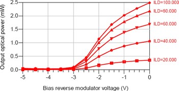
Fig. 4. EML optical output power versus EAM reverse bias voltage V M for different laser bias currents ILD (mA).
This result reflects the behavior of both the laser diode and the EAM: the EML optical output power increases significantly when the modulator reverse bias voltage exceeds −3 V. The optical intrinsic losses are well estimated through the EML, as its optical output power is five times as small as the laser output power, corresponding to the 7 dB optical intrinsic losses.
Figure 5 illustrates the typical static behavior of the SMF coupled optical output power of the EML. The optical power decreases as the reverse modulator voltage increases.

Fig. 5. EML optical output power versus laser bias current ILD for various reverse bias voltages V M (V).
C) Electrical-to-electrical and electrical-to-optical responses
The electrical-to-electrical (E/E) and electrical-to-optical (E/O) responses were measured using an Anritsu 37397C vector network analyzer and an Anritsu MN4765A photodetector over a wide frequency band up to 65 GHz. The frequency response of the photodetector was de-embedded from the responses of the EML. The EML temperature was fixed to 20 °C for each measurement owning to a temperature controller.
Figure 6 shows the measured RF input reflection coefficient S 11 of the EML for two optical powers and at a reverse bias voltage of 2.8V: this return loss varies very slowly with the laser bias current ILD. The solid curve is the simulated S 11 magnitude from the model. According to measurements, the circuit model provides a good fit. The reflection coefficient of the EML is lower than −9 dB in a wide bandwidth up to 65 GHz.

Fig. 6. Measured and simulated E/E responses of the EML.
The measured and simulated E/O responses are plotted in Fig. 7. The laser current was fixed to 30 mA and the modulator bias voltage to −2.8 V. A good agreement between measured and simulated curves is observed, showing a difference of less than 1 dB till 60 GHz: a more precise study of the laser influence is necessary at higher frequencies, but not necessary in this work. According to the flatness of the measured curve, the 3 dB cut-off frequency is near 37 GHz, enabling a 40 Gbps operation.

Fig. 7. Measured and simulated relative E/O responses of the EML.
These results clearly indicate that our developed model can properly consider the optical-microwave interaction. Therefore, this model can be applied to evaluate the performances of an optical transmitter in an RF photonic link.
III. UWB-OFDM SIMULATION RESULTS
The nonlinear model of the EML can be used in time and frequency domains. In transient analysis, we can simulate time waveforms and eye diagrams, for various modulating electrical signals. In frequency analysis, we can simulate transmission gain, 1 dB compression point and IP3.
The great interest of UWB RoF systems is the ability to increase transmission distances and high data bit rates [Reference Le Guennec, Lourdiane, Cabon, Maury and Lombard24]. Therefore, we studied the capabilities of our EML model to predict transmission of UWB signals over fiber. One area of interest is to include the EML in an RoF system using a standard intensity modulation technique with an external modulation and a direct detection.
Two different groups impact on the standardization of UWB systems: impulse radio single carrier UWB (IR-UWB) and multi-band (MB) UWB using the well-established modulation schema orthogonality frequency dividing multiplexing OFDM (UWB-OFDM) [Reference Paquelet, Aubert and Uguen25].
Among all the various transmission techniques using UWB labeled modulations, UWB-OFDM signals are chosen in this study to simulate the impact of the E/O transmitter in an RoF link.
For UWB-OFDM signal processing simulation and mixed signal cosimulation, ADS-Ptolemy simulator is used. The EML circuit model is considered as a sub-network and is included in a signal processing schematic. This circuit block can then be considered as a signal-processing component, as it is simulated independently using a circuit envelope simulator, reflecting its real behavior. ADS-Ptolemy provides the signal processing simulation, while the analog/RF simulation is provided by the circuit envelope. This is done by placing a circuit-envelope-specific component in the diagram.
A) UWB-OFDM signal description
OFDM is one of the most usual techniques for broadband data communications because of its robustness in multi-path propagation environments, its immunity to fading channels, and its tolerance of delay spread [Reference Van Nee and Prasad26]. OFDM techniques are extremely popular for wireless communications to achieve very high data rates and are the based algorithm technology for standards such as WLAN 802.11, WiMax 802.16, and MBWA 802.20.
The particularity of MB-OFDM systems is to associate a modulation of broadband OFDM symbols to a frequency hopping spread spectrum.
In a classical OFDM system, the available channel bandwidth B is divided into N orthogonal sub-channels and data symbols are transmitted in parallel over these sub-channels with a long symbol duration to deal with the frequency-selective fading of wireless channels [Reference Batra and Balakrishnan27]. The OFDM block duration Ts is N times as large as in the case of a single-carrier transmission system covering the same bandwidth. Hence, OFDM implies an enhanced robustness against time dispersion. OFDM uses the fast Fourier transform algorithm to mathematically transform signals.
By fixing the frequency bandwidth B of OFDM symbols to 528 MHz [Reference Van Nee and Prasad26], the whole available UWB spectrum (3.1–10.6 GHz) is divided into 14 identical sub-channels. The number of sub-carriers is N = 128 and the OFDM symbol duration is fixed to Ts = 242.42 ns. The data rate of MB-OFDM systems is typically from 53 to 480 Mbps, depending on the used signal mapping and constellation.
B) UWB-OFDM transmitter
Figure 8 shows the simplified block diagram of the UWB-OFDM source.

Fig. 8. Block diagram of the UWB-OFDM source.
A numerical data source generates a random bit sequence of equal probability. Therefore, the bit pattern will be different for each instance of the bits component.
A 16-state quadrature amplitude modulation (16-QAM) is performed on the input bit stream, producing a complex output signal.
The 16-QAM-constellation diagram of the input data is shown in Fig. 9: with four I-values and four Q-values, 16 possible states are afforded for the signal. Consequently as 16 = 24, 4 bits per symbol can be sent.

Fig. 9. The 16-QAM perfect constellation diagram of the input data.
A normalization gain factor is introduced to adjust the power level of the 16-QAM modulated signals. The OFDM modulator itself is made of an inverse Fourier transform algorithm (IFFT) and a raised-cosine filter with a roll-off factor equals to 0.25. According to the proposed standard, an IFFT size of 7 is used. The UWB-OFDM baseband signal is then up-converted by a mixer to the chosen RF center frequency of the required band. In our study, two carrier frequencies of OFDM symbols are chosen in the sub-channel 2 (3.96 GHz) and an upper one (7.5 GHz).
The main MB-OFDM signal simulation parameters used are summarized and listed in Table. 1.
Table 1. MB-OFDM simulation parameters.

Figure 10 shows the RF spectrum of the UWB-OFDM signal applied to the RF input of the EML (i.e. at the output of the up-converter). We clearly obtain an UWB-OFDM signal at 3.96 GHz frequency and a bandwidth of 528 MHz, corresponding to one of the 128 sub-channels. The power level has to be low in order to preserve the linear working of the EAM.

Fig. 10. PSD of an UWB-OFDM signal in a sub-channel at the input of the EML.
C) EML responses to an applied UWB-OFDM signal
The shape of the UWB-OFDM signal spectrum at the output of the EML is illustrated in Fig. 11.

Fig. 11. PSD of the UWB-OFDM optical signal at the output of the EML.
Co-simulation results show that the MB-OFDM modulation is well transmitted through the EML at the optical signal. We can notice the increase of the noise on the adjacent channels, especially if the laser RIN is enabled in the DFB laser model. In this case, at the output of the EML, the power level difference, between available channel and adjacent channels, is reduced, decreasing from 90 to 40 dB.
The influence of the laser RIN on the UWB-OFDM optical spectrum is shown in Fig. 12. The power spectral density (PSD) is, respectively, plotted for two laser bias currents, 50 and 100 mA, corresponding to measured RIN values of −147 and −157 dB/Hz at 3.96 GHz.

Fig. 12. Influence of the laser RIN on the UWB-OFDM signal spectrum.
The simulation results show a decrease of the noise power level in adjacent channels for an increase of the laser bias current. Indeed, the RIN laser is stronger for a lower laser bias current as shown in Fig. 13. An analytical evaluation of the RIN level for these two bias currents gives a relative level near −60 and −70 dB, respectively, while there are 10 and 5 dB lower in simulation.

Fig. 13. Simulated laser RIN versus frequency from measurements.
When simulating in the higher sub-channel (7.5 GHz), we can also see the influence of the laser RIN versus frequency on the UWB-OFDM signal spectrum. Figure 14 represents the output optical spectrum when the carrier frequency is near the DFB laser relaxation frequency for a 50 mA-biased current. At such a frequency, the RIN value is highest and the difference between the two curves of Fig. 13 is larger than at 3.96 GHz. As expected in Fig. 14, the power level in adjacent channels increases (up to 10 dB compared to the 3.96 GHz sub-channel) and the effect of laser RIN with its bias current is clearly observed on the simulated UWB-OFDM signal spectrum. A same analytical evaluation of the RIN power level for these two bias currents gives a relative level near −52 and −62 dB, respectively. The same conclusion can be made as before.

Fig. 14. PSD of the UWB-OFDM optical signal at the EML output at the 7.5 GHz sub-channel.
D) UWB-OFDM optical link
The simulated RoF transmission link structure is an externally modulated fiber radio link with direct detection. Figure 15 shows a block diagram of the simulated UWB RoF system.

Fig. 15. Block diagram of the simulated UWB radio over fiber system with an external intensity modulation of the laser.
As described in Section II, the optical transmitter uses an EAM integrated DFB laser (EML) specified for 40 Gbps application. The output of the EML is connected to an optical fiber before being received on a photoreceiver. The output of the photodetector is connected to an UWB-OFDM receiver and an error detector. The bit error ratio (BER) or the error vector magnitude (EVM) can be computed by comparing input and output data. The optical system operates at a wavelength of 1550 nm.
The principle of the electro-optical transmitter is as follows: the optical carrier of the DFB laser at 1550 nm is intensity modulated with the MB-OFDM signal applied to the EAM electrical input. Thus, the modulated optical signal is launched to the fiber and detected by the PD. The received MB-OFDM signal is then down-converted, amplified, and demodulated to regenerate the binary data.
As SMF offers very wide bandwidth, very low attenuation, and high linearity, a 1.55 µm standard SMF associated to a propagation loss of 0.2 dB/km and a dispersion coefficient of 17 ps/nm/km is used. To perform the direct detection, a high-speed PIN PD with a responsivity of 0.8 A/W and a frequency bandwidth of 20 GHz is needed to convert the intensity-modulated optical signal back into the electrical data signal.
The simulated system is divided into two parts: the electronic sub-system and the optical sub-system. The electronic sub-system gathers the UWB-OFDM transmitter and receiver, including devices as the OFDM modulator, an amplifier, a bandpass filter, and a frequency down or up-mixer. The optical sub-system corresponds to the optical link including the DFB laser, the EAM, the standard single-mode fiber, and the PIN PD.
For the optical sub-system, physical characteristics of each device are taken into account: the laser RIN, the SMF loss and its dispersion characteristic, the PIN dark current and thermal noise, as well as the nonlinear properties of the EAM. The nonlinear properties of these optical devices have been modeled in ADS [Reference Bdeoui, Billabert, Polleux, Algani and Rumelhard18, Reference Deshours, Algani, Blache, Alquié, Kazmierski and Jany19] and individually verified through experiment. So, by adding well-established models of optical fiber and PD, ADS-Ptolemy can simulate the complete transmission link performance of the RoF system represented in Fig. 15.
Figure 16 shows the recovered UWB-OFDM signal spectrum at the output of the RoF link. OFDM signal in the 3.96 GHz sub-channel with a large bandwidth of 528 MHz is obtained, demonstrating the good 16-QAM OFDM data transmission in radio on fiber systems for an optical distance of 100 m. As it can be clearly seen from Fig. 16, the PD thermal noise does not impact on the adjacent channels. However, as it was shown before, the laser RIN is not negligible. The laser bias current is fixed at 100 mA.

Fig. 16. PSD of the UWB-OFDM electrical signal at the output of the RoF link.
In order to evaluate the link performance and the influence of each optical device, the received signal is frequency down-converted and analyzed by the resulting constellation (Figs 17 and 18): RIN clearly introduced average error power on each symbol.

Fig. 17. 16-QAM-constellation diagram of the received data neglecting the laser RIN.

Fig. 18. 16-QAM-constellation diagram of the received data including the laser RIN (ILD = 50 mA).
The constellation diagram for recovered 16-QAM data signal in RoF transmission displays phase errors, as well as amplitude errors at the decision points. Major sources of performance degradation and limitation of UWB fiber radio link are noise and nonlinearities induced by the optical devices: DFB laser and EAM exhibit undesirable intermodulation products when they are driven with multi-tone radiofrequency signals [Reference Le Guennec, Lourdiane, Cabon, Maury and Lombard24].
IV. CONCLUSION
We presented an original modeling method to implement a complete large signal model of an EAM integrated DFB laser in a high-frequency commercial simulator. This simulation way can provide an accurate and powerful tool to simulate the behavior of EML driving by analog or digital electrical signals. By exploiting the already existing models of optical fiber and PD, it is possible to analyze a complete RoF system and to predict the impact of both the electronic-optical transmitter and the microwave electrical circuits on the link performances when transmitting UWB-OFDM signal. Deeper simulations have to be investigated and compared to EVM or BER measurements.
 Frédérique Deshours was born in Vichy, France, in 1969. She received the Ph.D. degree in electronic and telecommunications in 1996 from both the UPMC University Paris 6, France and Telecom ParisTech, France. Since 1997, she has joined the Electronic and Electromagnetic Laboratory (L2E) of the University of Paris 6, France, as an assistant professor. She began to work in the simulation, design, and measurement of microwave and millimeter-wave integrated circuits. Her current research interest is focused on the modeling of high-speed electro-absorption modulators for radio-over-fiber communications and the development of millimeter-wave architectures of ultra-wide band transmission systems with optical link.
 Anne-laure Billabert was born in Cholet, France, in 1972. She received the engineering degree in electronics from IRESTE, University of Nantes, France, and the DEA degree in electronic and radar from the University of Nantes, France, both in 1995. She received the Ph.D. degree in radar polarimetry field in 1999 from the University of Nantes, France. Since 1999, she has joined the ESYCOM Laboratory and Cnam, Paris, France, as an assistant professor. Her current research is centered on the topics of opto-microwave, mainly the simulation of opto-microwave link.
 Catherine Algani was born in Thionville, France, in 1963. She received, from the University of Paris 6, France, the DEA degree in electronics, and the Ph.D. degree, respectively in 1987 and 1990. Her dissertation concerns the area of active MMIC design using GaAs HBTs technology in CNET-Bagneux. In 1991, she joined the Electronics Engineering Department and the LISIF Laboratory, at University of Paris 6, as a lecturer. From 1991 to 2005, she worked on the design of microwave and millimetre-wave integrated circuits on different GaAs technologies. In 1997, she began to work in the area of microwave photonics (optically controlled microwave switches on GaAs and electro-optic organic modulator). In 2005, she joined ESYCOM at CNAM-Paris, where she is currently a full professor. Her current research interests are the development of devices, circuits, and sub-systems for ultrahigh speed digital and analog communications for ROF and wireless applications. These researches include the modeling, the design, and the characterization of such structures.
 Fabrice Blache received the Ph.D. degree in electronics from the University of Limoges, Limoges, France, in 1995. He is currently a research engineer with the Alcatel Thales III-V Lab, in Marcoussis, France, a joint laboratory of Alcatel-Lucent Bell Labs France and Thales Research & Technology, where his main expertises are in the field of high-frequency designs for opto-electronic modules. He is currently leading research activities for 40 and 100 Gb/s applications.
 Christian Rumelhard qualified as an electronic engineer in 1966 and received a Docteur Ingénieur degree in 1977 (Paris-6 University). He worked at Thomson-CSF on the design of microwave tubes until 1969, on the design of hybrid microwave integrated circuits until 1975, and then he developed CAD algorithms and numerical models for the simulation of microwave circuits and devices. In 1980, he created an MMIC Laboratory in the Central Research Laboratory of Thomson-CSF. In 1985, he was in charge of a design and characterisation team in the Gallium Arsenide Department of this company. During the 1980–1990 decade, tens of MMICs were designed and characterized in his different teams. This activity resulted in many communications and contributions to four different books on microwave circuits. In 1992, he became Professor in Conservatoire National des Arts et Métiers, Paris where he worked on simulation, design, and measurement of microwave and photonic devices (SiGe HPT), circuits, and systems. From 1997 to 2005, he was Director of Equipe Systèmes de Communication et Microsystèmes (ESYCOM), a common research team between CNAM, ESIEE and University of Marne-la-Vallée. He is now Professor Emeritus at CNAM. In October 2000, he was general chairman of the 3rd European Microwave Week in Paris.
 Georges Alquié received the Master of Sciences in Physics from the University of Montpellier (Montpellier,France), the PhD degree from the University of Orsay (Orsay, France), and the high level doctorate from the University Pierre and Marie Curie (Paris, France) in 1977. He is currently Professor in Electrical Engineering at the University of Pierre et Marie Curie, mainly involved in the solid state devices physics, the microwave techniques, and electromagnetism. His research activity, which concerns the microwave and millimeter domain, is performed at the “Laboratoire d'Electronique et Electromagnétisme” (L2E). He is involved in the design and modeling of integrated passive circuits, integrated low noise active microwave devices (MMICs), and microwave photonics devices for telecommunications and defence applications. In the L2E, he has also in charge of the research management of several projects in the field of UWB communications.


