


1. Introduction
The Himalaya is a result of continental collision between India and Eurasia and is characterized by both pre- and syn-Himalayan magmatism. The syn-Himalayan Cenozoic leucogranite can be divided into two types (King et al. Reference King, Harris, Argles, Parrish and Zhang2011; Guo & Wilson, Reference Guo and Wilson2012). The Greater Himalayan Leucogranite (GHL) is present within and along the northern margin of the Himalayan metamorphic core or the Greater Himalayan Sequence (GHS), having ages ranging from ~25 to ~9 Ma. North of this GHL, along the North Himalayan Antiform, lies the chain of Tethyan Himalayan Leucogranites (THL), having an age range of ~23 to ~12 Ma. Both these chains of leucogranite are orogen-parallel and strike roughly east–west, with younger ages in the eastern parts of the Himalaya (Fig. 1a).
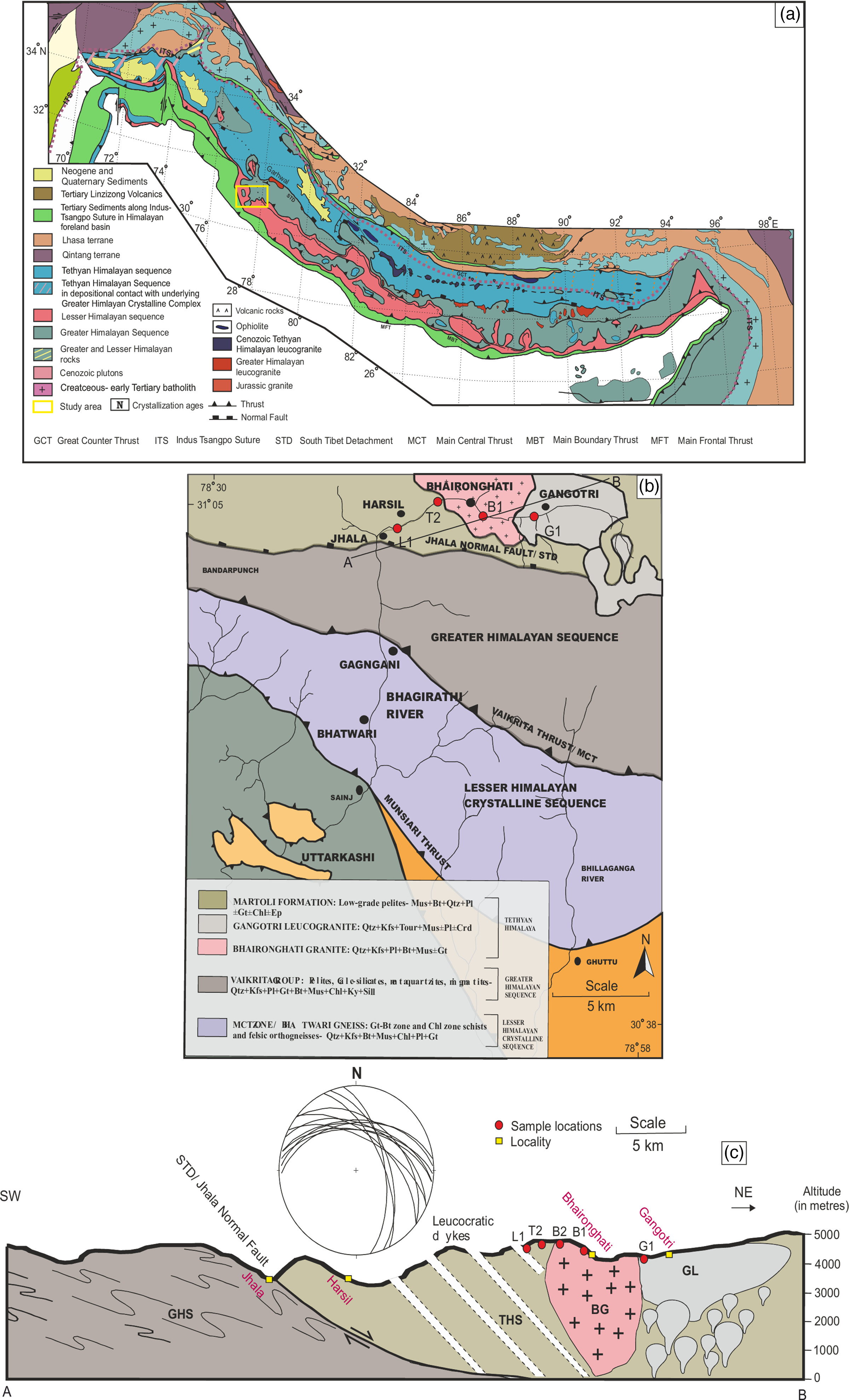
Fig. 1. (a) Generalized geological map of the Himalaya (modified after Yin, Reference Yin2006). Yellow box represents the study area. (b) Geological map of the Bhagirathi Valley of Western Garhwal Himalaya, Uttarakhand (modified after Metcalfe, Reference Metcalfe, Treloar and Searle1993). (c) Geological cross-section (AB) of the study area shown in (b). Locations and samples used for various analyses are also shown.
Both the source and petrogenesis of these suites of leucogranites have been a matter of conjecture. Some researchers opine that both Greater Himalayan and Lesser Himalayan components were involved in the generation of these leucogranites (Garzanti et al. Reference Garzanti, Casnedi and Jadoul1986; Le Fort et al. Reference Le Fort, Cuney, Deniel, France-Lanord, Sheppard, Upreti and Vidal1987; Visonà & Lombardo, Reference Visonà and Lombardo2002). However, many others have suggested that the GHS was the sole contributor (Harris & Massey, Reference Harris and Massey1994; Guillot & Le Fort, Reference Guillot and Le Fort1995; Harrison et al. Reference Harrison, Grove, McKeegan, Coath, Lovera and Le Fort1999; Zhang et al. Reference Zhang, Harris, Parrish, Kelley, Zhang, Rogers, Argles and King2004). Guo & Wilson (Reference Guo and Wilson2012) suggested that these leucogranites are derived from the bulk of the GHS crust with some amount of Lesser Himalayan fluid, while Hopkinson et al. (Reference Hopkinson, Harris, Warren, Spencer, Roberts, Horstwood and Parrish2017) argued that GHL is entirely formed by partial melting of the GHS.
Plausible petrogenetic models to explain the genesis of these leucogranites also vary from muscovite-dehydration melting (Patiño Douce & Harris, Reference Patiño Douce and Harris1998; Phukon et al. Reference Phukon, Sen, Singh, Sen, Srivastava and Singhal2019) to biotite-dehydration melting (Visonà & Lombardo, Reference Visonà and Lombardo2002; Visonà et al. Reference Visonà, Carosi, Montomoli, Tiepolo and Peruzzo2012; Groppo et al. Reference Groppo, Rolfo and Indares2013) to decompression melting (Zhang et al. Reference Zhang, Harris, Parrish, Kelley, Zhang, Rogers, Argles and King2004, Reference Zhang, Harris, Parrish, Zhang, Zhao and Li2005) and water flux melting (Harris & Massey, Reference Harris and Massey1994; Davidson et al. Reference Davidson, Grujic, Hollister and Schmid1997). Thus, inferring a uniform source and postulating one single petrogenetic model for the Himalayan leucogranites can be misleading. These leucogranites need to be characterized in terms of their emplacement mode, relationship with host rocks, petrology and age along with tectonic setting to understand their evolution with respect to the Himalayan tectonics.
As well as the syn-collisional leucogranites, a separate batch of pre-collisional Palaeozoic two-mica granites is also present along-strike Himalaya, adjacent to the South Tibetan Detachment (STD). The source, emplacement mechanisms and the tectonic settings in which these plutons evolved are still a matter of debate. The origin of these granites is attributed to the final assembly of Gondwana (Meert & Van der Voo, Reference Meert and van der Voo1997; Miller et al. Reference Miller, Thöni, Frank, Grasemann, Klötzli, Guntli and Draganits2001; Lee et al. Reference Lee, McClelland, Wang, Blythe, McWilliams and Law2006; Wang et al. Reference Wang, Zhang, Santosh, Liu, Yan and Guo2012). Miller et al. (Reference Miller, Thöni, Frank, Grasemann, Klötzli, Guntli and Draganits2001) suggested that they generated in a non-arc extensional domain, whereas Cawood et al. (Reference Cawood, Johnson and Nemchin2007) argued that these melts originated due to volcanic arc magmatism in a collisional setting. Robust geochemical analysis of widespread volcanic rocks (basalts, andesites and felsic rocks) along the margin of Gondwana in the Tethyan Himalaya (Valdiya, Reference Valdiya1995), as well as within the Lhasa terrane, along the northern margin of Gondwana (Zhu et al. Reference Zhu, Zhao, Niu, Dilek, Wang, Ji, Dong, Sui, Liu, Yuan and Mo2012), indicated volcanic-arc or arc-related magmatism as a cause for emplacement of these Palaeozoic granites. Combining geochemical and geochronological analysis, Wang et al. (Reference Wang, Zhang, Santosh, Liu, Yan and Guo2012) suggested that the entire span of this ~500 Ma magmatism can be attributed to volcanic arc and associated back-arc rift magmatism.
The Bhagirathi Valley of Garhwal Himalaya, India, is an ideal section from western Himalaya where both pre-collisional Palaeozoic two-mica granites and syn-collisional leucogranites and leucocratic dykes are present at various structural heights (Fig. 1b–c). For this study, we have carried out outcrop-scale and petrographic study coupled with geochemical (major, minor and trace element) and geochronological (zircon U–Pb laser ablation multi-collector inductively coupled plasma mass spectrometry (LA-MC-ICP-MS)) analyses of these aforementioned suites of two-mica granites, leucogranites and associated Tethyan rocks. Based on this information, we have postulated a comprehensive tectonic model to explain the geodynamics of this part of the Himalaya with respect to magmatism of different suites of granitic bodies.
2. Geology of the study area
In the Bhagirathi Valley, the Main Central Thrust (MCT), the major shortening accommodating the intra-terrane fault zone in the Himalaya, forms a ~12 km thick NNE-dipping shear zone that separates Lesser Himalayan Formations from the Vaikrita Group or the Greater Himalayan Sequence (Metcalfe, Reference Metcalfe, Treloar and Searle1993; Fig. 1b–c). The GHS is a ~30 km package of metamorphic rocks composed of sillimanite- and kyanite-bearing garnetiferous schist/gneisses (Metcalfe, Reference Metcalfe, Treloar and Searle1993; Singh, Reference Singh2003). At the structural top of the GHS, a N-dipping fault, the Jhala Normal Fault (JNF), forms the boundary between the GHS and the low-grade Tethyan Himalayan Sequence (THS). The grade of metamorphism increases towards the top of the GHS in a northward direction where sillimanite + K-feldspar gneisses are intercalated with foliated, anatectic granites (Metcalfe, Reference Metcalfe, Treloar and Searle1993). Further north, overlying the GHS, is the lowest part of the THS, namely the Harsil Formation (R Pant, unpub. Ph.D. thesis, Roorkee Univ., 1986). The Harsil Formation / THS is low-grade metapelite. The JNF demarcates the southern margin of the study area. Different litho-units of the present study area are introduced in the following section.
The sample locations are plotted in Figure 1b. The sample locations, litho-unit/structural positions and various analytical techniques used for each sample are listed in Table 1. The collective dataset from the samples classifying the individual outcrops are THS (T2), leucocratic dyke (L1), Bhaironghati Granite (B1) and Gangotri Leucogranite (G1).
Table 1. Locations and types of samples used for analysis

* One common sample is used for U–Pb zircon geochronology and geochemistry. Three to four samples per lithology were used for petrography.
2. a. Jhala Normal Fault (JNF)
The Jhala Normal Fault (JNF) marks the boundary between the GHS and the THS. It has been a matter of conjecture whether the JNF is the actual South Tibetan Detachment, i.e. the regional tectonic boundary between the THS and GHS across the western and central Himalaya. The JNF activated after 15 Ma as constrained from the apatite fission track ages (Sorkhabi et al. Reference Sorkhabi, Stump, Foland, Jain, Jain and Manickavasgam1999). Earlier mapping by Pêcher (Reference Pêcher1991) and a review by Yin (Reference Yin2006) suggested that Jhala is a N-directed brittle thrust zone superposed on a zone of dominantly N-verging ductile folds in garnet–biotite gneiss and schist. They also suggested that the actual STD is likely located at a higher structural level than the ‘Jhala thrust’ of Pêcher & Scaillet (Reference Pêcher and Scaillet1989) and the Jhala ‘normal’ fault of Metcalfe (Reference Metcalfe, Treloar and Searle1993). Metcalfe (Reference Metcalfe, Treloar and Searle1993) inferred that the JNF is a N-dipping normal fault separating the Greater Himalayan Crystallines (GHS) from the Tibetan–Tethyan sediments. He also suggested localized shear and the presence of normal-sense brittle offsets.
Metamorphic grade within the GHS increases towards the north until it reaches sillimanite/kyanite mica schist/gneiss before passing into migmatite (Scaillet et al. Reference Scaillet, Pêcher, Rochette and Champenois1995; Singh, Reference Singh2018). Our field observations suggest that further north, near Jhala (Fig. 1b), there is a complete change in lithology with the occurrence of very low-grade biotite/chlorite schist. A set of fractures trending NE and a set of local-scale N-verging folds appears within the THS. Fault gouges and cataclasites are well exposed in the road-cut section along the Jhala Bridge (Fig. 2a). Asymmetric quartz clast (Fig. 2b), mica-fish and quarter structures showing top-to-the-N shearing suggest deformation features related to extensional faulting.

Fig. 2. Outcrop-scale features. (a) Fault-gouges in the hanging wall of Jhala Normal Fault (JNF). (b) Quartz clasts within the THS showing top-to-the-N or down-dip shearing suggesting extensional movement. (c) Leucocratic dykes intruding the THS. (d) Asymmetric quartz boudins showing top-to-the-N / extensional shearing. (e) Close-up view of tourmaline-bearing leucocratic dyke intruding the THS. (f) Fault propagation fold near the contact of THS and BG. (g) Contact between BG and THS (marked as ‘H’). (h) Typical coarse-grained two-mica granite of BG. (i) Mafic microgranitoid enclaves within the BG. (j) Contact between BG and GL. (k) GL intruding BG; biotite is completely absent, tourmaline occurs as blebs and clasts and some fractures are present randomly along which aplite veins appear.
2.b. Harsil Formation / THS and leucocratic dykes
The THS is intruded by a series of leucocratic dykes as we move structurally up-section (Fig. 2c). These dykes are 5–7 m thick and are at an inclination of 30–35° (see also Stern et al. Reference Stern, Kligfield, Schelling, Fruta and Virdi1989; Scaillet et al. Reference Scaillet, Pêcher, Rochette and Champenois1995; Singh et al. Reference Singh, Mukherjee, Jain, Khanna, Sain and Kumar2003; Singh, Reference Singh2018). Quartz clasts within the THS show top-to-the-N or down-dip shearing suggesting extensional faulting (Fig. 2d). These dykes are mainly composed of quartz–K-feldspar aggregates with muscovite and ample amounts of tourmaline (Fig. 2e). The orientation of these dykes is sub-parallel to the regional foliation. A large-scale en-echelon pattern is noted, as the majority of the garnet–tourmaline-bearing dykes are oriented NNW and dipping ENE. The dyke orientation may be a consequence of sliding at the top of the metamorphic pile (chlorite–biotite schist + leucogranite) toward the N or NW during or after the leucocratic dyke injection (Scaillet et al. Reference Scaillet, Pêcher, Rochette and Champenois1995, Reference Scaillet, Holtz, Pichavant and Schmidt1996). The low-grade metamorphic rocks of the THS are chlorite–biotite schists with a uniformly N-dipping penetrative foliation (R Pant, unpub. Ph.D. thesis, Roorkee Univ., 1986). These rocks have undergone very low-grade metamorphism, probably in the lower greenschist facies during activation of the JNF (Metcalfe, Reference Metcalfe, Treloar and Searle1993), and are characterized by the presence of small-scale fault-propagation folds near the contact with the Bhaironghati Granite (Fig. 2f).
2.c. Bhaironghati Granite (BG)
The BG is present to the north of the THS. As noted by Stern et al. (Reference Stern, Kligfield, Schelling, Fruta and Virdi1989), the petrographic and geochemical characteristics of this granite are very similar to those of the Cambro-Ordovician magmatism defined by Le Fort (Reference Le Fort, Coward and Ries1986) for the entire Himalayan belt. Stern et al. (Reference Stern, Kligfield, Schelling, Fruta and Virdi1989) also reported that BG structurally underlies the tourmaline leucogranite and is spatially related to the upper part of the Tibetan Slab, whereas Scaillet et al. (Reference Scaillet, France-Lanord and Le Fort1990) suggested that BG is located above the Tibetan slab. The BG first appears east of Harsil (Fig. 1b), having a sharp contact with the THS (Fig. 2g; Manickavasangam et al. Reference Manickavasagam, Jain, Singh, Asokan, Macfarlane, Sorkhabi and Quade1999; Singh, Reference Singh2003, Reference Singh2018). It is a coarse-grained two-mica granite (Fig. 2h) and is characterized by mafic microgranitoid enclaves (Fig. 2i). We observed that, although the biotite–muscovite granite is deformed along its lower margins, the interior of the pluton is not at all deformed. Further north, this biotite–muscovite granite is cut by younger bodies of muscovite–tourmaline granite and garnet–beryl–tourmaline pegmatite (Fig. 2j), which are related to the overlying Gangotri Leucogranite.
2.d. Gangotri Leucogranite (GL)
Leucogranites from the upper Bhagirathi Valley make up several lenses or small plutons, 1.5–2 km thick and 4–5 km long, rather than a single body such as the Manaslu pluton (Scaillet et al. Reference Scaillet, Dardel and Le Fort1988). These lenses are intrusive either in the base of the THS or in the BG (R Pant, unpub. Ph.D. thesis, Roorkee Univ., 1986). The GL appears at the western end of the BG (Fig. 2j, k). It is one of the largest Himalayan leucogranite plutons (Heim & Gansser, Reference Heim and Gansser1939; Gansser, Reference Gansser1964; Le Fort, Reference Le Fort1975). It was first described by Heim & Gansser (Reference Heim and Gansser1939) from the upper Alaknanda Valley, near Badrinath village. It was also recognized by Auden (Reference Auden1949) in the upper Bhagirathi Valley, who named it ‘Gangotri granite’. In the present study area, it crops out as several lenses scattered over more than 400 km2, each of which is several kilometres in length with laccolithic shape (Scaillet et al. Reference Scaillet, France-Lanord and Le Fort1990). Muscovite K–Ar ages of 18.4 ± 0.7 Ma were obtained from this leucogranite (Stern et al. Reference Stern, Kligfield, Schelling, Fruta and Virdi1989). The Th–Pb isotopic monazite age obtained is 22.4 ± 0.5 Ma (Harrison et al. Reference Harrison, Lovera and Grove1997). Sorkhabi et al. (Reference Sorkhabi, Stump, Foland, Jain, Jain and Manickavasgam1999) carried out Ar–Ar dating on muscovite separates from the GL and obtained a plateau age of 17.9 ± 0.1 Ma.
The GL is usually characterized by a very weak foliation, defined by mica and tourmaline. The granite body is mainly massive with the presence of small-scale extensional fractures and aplite dykes near its contact with the BG. Near the contact, the foliation grades into layering which includes a few cm-thick bands of tourmaline (Singh, Reference Singh2003). Tourmaline and muscovite are the dominant minerals apart from the quartzo-feldspathic aggregate. Muscovite is mainly enclosed within plagioclase and K-feldspar and its abundance generally decreases as we move away from the contact between GL and BG.
3. Petrography
3.a. T2
The THS (T2) is composed of sedimentary rocks that grade into low-grade metasediments in the vicinity of the JNF. Near the contact between the THS and BG, the appearance of subhedral garnet (Fig. 3a) suggests that a localized higher-order metamorphic event had taken place by accompanying the ductile deformation during the intrusion of the BG. This is also evident from the warping of biotite grains around garnet (Fig. 3a). Apart from this, the general mineral assemblage is quartz, K-feldspar, chlorite, biotite and rarely muscovite (Fig. 3b). Zircon, apatite and rutile occur as minor phases. Biotite and chlorite flakes occur in a preferred direction depicting the main transposed foliation.

Fig. 3. Photomicrographs of representative samples (T2, L1, B1, G1). (a) Sample from the THS near its contact with the BG (T2-B) showing garnet–biotite assemblage along with a quartzo-fedspathic mass. (b) THS away from contact (T2-A) with BG showing mineral assemblage of quartz, K-feldspar, plagioclase and biotite. (c, d) Leucocratic dykes showing presence of garnet, plagioclase, quartz, tourmaline and sillimanite. (e) BG near its contact with the THS (BG-2) showing presence of garnet porphyroblast warped by a tectonic foliation defined by muscovite. (f) Plagioclase from interior part of BG (BG-1) showing concentric inclusion pattern and compositional zoning. (g, h) Sample from GL showing presence of plagioclase, quartz, muscovite and tourmaline. The mineral abbreviation scheme adopted is as follows: Gt (Garnet), Bt (Biotite), Mus (Muscovite), Pl (Plagioclase), Mc (Microcline), Tour (Tourmaline), Sill (Sillimanite) and Qtz (Quartz).
3.b. L1
The leucocratic dyke (L1) has an assemblage of garnet + quartz + plagioclase + tourmaline ± muscovite ± sillimanite (Fig. 3c, d). Plagioclase grains have developed a fracture plane other than the prominent cleavage plane. Tourmaline is generally inclusion-free and is comparatively small in size. The muscovite flakes are comparatively large in size and oriented in a preferred direction. The presence of small homogeneous garnets (Fig. 3d) suggests their igneous origin. The appearance of sillimanite needles (Fig. 3c) suggests that the temperature during in situ melt intrusion was sufficiently high.
3.c. B1
BG (B1) is a coarse-grained rock exhibiting granular texture. It is mainly composed of quartz, plagioclase, K-feldspar, biotite and muscovite (Fig. 3e, f). This is basically a two-mica granite having well-defined boundaries of quartz. Plagioclase shows a concentric inclusion pattern and compositional zoning (Fig. 3f). Plagioclase, K-feldspar and mica occur mainly in euhedral to subhedral form. Garnet is present only along the contact of BG with the THS. One sample (B2) taken from the periphery of BG shows syn-kinematic garnet with mica warping around the garnet porphyroblast (Fig. 3e).
3.d. G1
GL is typically a tourmaline–muscovite leucogranite with quartz, K-feldspar and plagioclase occurring as the major phases and apatite and beryl as minor phases (Fig. 3g, h). Tourmaline grains contain numerous inclusions of quartz and plagioclase as well as apatite, but are totally free of K-feldspar inclusions. Muscovite is quite abundant (10–13 % modal) in this rock. It is mainly enclosed within quartz and K-feldspar and is always in textural equilibrium with other phases. However, rare overgrowth of muscovite on K-feldspar is present as typical symplectite texture. Biotite grains are rare and mostly enclosed within muscovite with a diffused boundary.
4. Analytical techniques
4.a. Bulk rock geochemistry
Major oxides and trace element concentrations were measured, using pressed powder pellets made with 7 g rock powder, by WDXRF (Bruker S8 Tiger) at the Wadia Institute of Himalayan Geology. Representative samples were crushed and pulverized up to 200 mesh size using an agate carbide ring grinding bowl. Polyvinyl alcohol was mixed as a binding agent with the rock powder to make the pressed pellets. A separate 0.5 g powder of each sample was heated at 1000 °C for 8 hours to determine the loss-on-ignition (LOI). Analytical accuracies for major elements and trace elements are well within ±2–3 % and ±5–6 % respectively. International reference samples GA, GH, GSN, MA-N (CRPG, France), G-2, GSP-1, RGM-1, AGV-1 (USGS, USA) and JG-2, JG1-a and JA-2 (GSJ, Japan) were used to check precision and accuracy. A modified Lucas-Tooth & Pyne (Reference Lucas-Tooth and Pyne1964) model with intensity-based matrix correction was used to derive the calibration coefficients.
An ICP-MS (Perkin-Elmer SCIEX ELAN DRC-e) was used at the Wadia Institute of Himalayan Geology to determine the rare-earth element (REE) concentrations for these same samples. An open-system digestion method was used to prepare the sample solution for REE analysis. Individual samples were powdered, 0.1 g from each sample was separately mixed in HF and HNO3 (2:1 ratio) solution in Teflon crucibles and they were heated over a hot plate until the powdered samples were completely digested. Accuracy ranges between 2 and 12 %, and precision varies between 1 and 8 % in case of REE analysis. JG-2 and MB-H are the rock standards used to calibrate the ICP-MS instrument.
4.b. Zircon U–Pb LA-MC-ICP-MS dating
Zircon U–Pb LA-MC-ICP-MS dating was carried out for one Gangotri Leucogranite (G1), one Bhaironghati Granite (B1), one low-grade metasedimentary rock of the THS (T2) and one leucocratic dyke sample (L1). A total of ~3–4 kg of rock samples was crushed and processed using a jaw crusher, disc mill, Holman Wilfley water table, isodynamic magnetic separator and heavy liquids to separate the zircon required. Thereafter, zircon was hand-picked under stereo microscope and was mounted in PFA® Teflon. Mounted zircon was polished using 8, 5, 3, 1 and 0.25 micron diamond paste. Cathodoluminescence (CL) images of mounted zircon were obtained using a Gatan Chroma CL UV attached to a Zeiss EVO 40 EP scanning electron microscope with a varying probe current of 10–20 nA at the Wadia Institute of Himalayan Geology. The U–Pb geochronology for the selected four samples was carried out at the LA-MC ICP-MS facility, Wadia Institute of Himalayan Geology. It consists of MC-ICPMS (Neptune-plus, ThermoFisher Scientific Inc.) and a 193 mm excimer laser (UV Laser, Model Analyte G2, Cetec-Photon machine Inc.), equipped with a high-performance HelEx-II sample chamber. The methodology adopted is similar to that of Phukon et al. (Reference Phukon, Sen, Singh, Sen, Srivastava and Singhal2019). The analyses were carried out with energy density 4 J cm−2, a repetition rate of 5 Hz, 75 % laser intensity and 175 total shots per analysis, i.e. 35 s analysis time for each spot with 10 s background measurement.
On the basis of the zoning pattern as revealed by the CL images of every sample, the spots were chosen. The spot sizes were fixed at 20 microns on the chosen zircon for U–Pb analysis. Zircon U–Pb downhole fractionation was corrected by using Z91500 as primary zircon standard. The normalization data for this primary standard is 1062.32 ± 2.22 Ma (206Pb/238U age) [2 sigma, thermal ionization mass spectrometry (ID-TIMS)] (Wiedenbeck et al. Reference Wiedenbeck, Alle, Corfu, Griffin, Meier, Oberli, von Quadt, Roddick and Spiegel1995). For the sake of accuracy, Plešovice zircon grains having a concordant age of 337.13 ± 0.37 Ma (ID-TIMS; Sláma et al. Reference Sláma, Kosler, Condon, Crowley, Gerdes, Hanchar, Horstwood, Morris, Nasdala, Norberg, Schaltegger, Schoene, Tubrett and Whitehouse2008) were used. In our analyses, Z91500 and Plešovice provide the average normalized 206Pb/238U ages of 1063.4 ± 1.7 Ma (0.16 %; MSWD = 0.85; 2σ; probability fit = 0.75; n = 44) and 340.6 ± 1.1 Ma (0.32 %; MSWD = 1.15; 2σ; probability fit = 0.23; n = 40) respectively. At the beginning and end of the analytical session, four analyses of each zircon standard were carried out and after every 10 analyses of unknown zircon grains from the studied samples, another two analyses of zircon standards were performed. Data reduction and plotting of data were carried out using Iolite software (Paton et al. Reference Paton, Hellstrom, Paul, Woodhead and Hergt2011) and online IsoplotR software (Vermeesch, Reference Vermeesch2018). Cup configuration and parameters for the LA and MC-ICPMS (Chang et al. Reference Chang, Vervoort, McClelland and Knaack2006; Gehrels et al. Reference Gehrels, Valencia and Ruiz2008;) are provided in Supplementary Material 1 (available online at https://doi.org/10.1017/S0016756821000789). The data-point error ellipse as well as the age uncertainties are quoted as 2σ error (Horstwood et al. Reference Horstwood, Kosler, Gehrels, Jackson, McLean, Paton, Pearson, Sircombe, Sylvester, Vermeesch, Bowring, Condon and Schoene2016; Spencer et al. Reference Spencer, Kirkland and Taylor2016).
5. Results
5.a. Bulk rock geochemistry
The complete dataset representing major, trace and REE concentrations of respective samples from different lithologies is provided in Table 2. Major element contents indicate that the GL and BG are peraluminous with aluminium saturation index (ASI = molecular ratio of Al2O3/(CaO + Na2O + K2O); Shand, Reference Shand1943) of 1.01–1.15 and 1.1–1.32 respectively (Fig. 4a). GL has high SiO2 (71.66–72.45 wt %) and Al2O3 (15.25–15.76 wt %) and low MgO (0.10–0.14 wt %) contents (Table 2). The Na2O concentrations in GL (4.21–4.46 wt %) are similar to those of K2O (5.25–5.30 wt %; Table 2). BG has relatively low Na2O (2.52–3.42 wt %) and high CaO (0.9–2.22 wt %) as compared to GL. However, the leucocratic dyke is highly silicic and oversaturated. The Rb vs Ba vs Sr plot (after El Bouseily & El Sokkary, Reference El Bouseily and El Sokkary1975) suggests that GL is a product of strong differentiation (Fig. 4b). Based on the classification of Frost et al. (Reference Frost, Barnes, Collins, Arculus, Ellis and Frost2001), GL can be called ferroan and alkalic to calc-alkalic, and plots within the field for peraluminous leucogranites. This indicates that GL is a product of crustal melts. The Al2O3 − (Na2O + K2O) vs CaO vs FeO + MgO plot suggests that both the BG and GL are S-type granites (Fig. 4c). In the Rb/Sr vs Ba diagram (Inger & Harris, Reference Inger and Harris1993), GL follows a muscovite vapour-absent trend as compared to the leucocratic dykes which follows a muscovite vapour-present trend (Fig. 4d). Feldspar fractionation trends (Fig. 4e–f) show dominantly K-feldspar fractionation for BG and plagioclase fractionation trend for GL.
Table 2. Major, trace and REE data for the samples of THS/THS (T2), leucocratic dyke (L1), Bhaironghati Granite (B1) and Gangotri Leucogranite (G1). Normalization values for trace element are after Taylor and McLennan (Reference Taylor and McLennan1985)
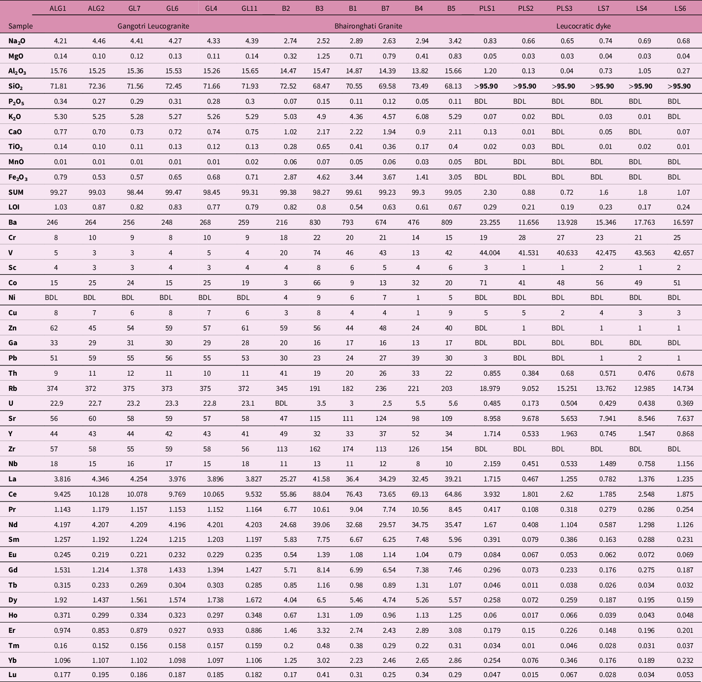

Fig. 4. (a) ACNK-ANK diagram for samples from GL and BG indicating the aluminium saturation index (ASI) (after Shand, Reference Shand1943). (b) Classification under the Rb vs Ba vs Sr diagram to decipher the differentiation trends of GL and leucocratic dykes (after El Bouseily & El Sokkary, Reference El Bouseily and El Sokkary1975). (c) Al2O3 − (Na2O + K2O) vs CaO vs FeOt + MgO diagram for both BG and GL (after Inger & Harris, Reference Inger and Harris1993). (d) Rb/Sr ratios vs Ba diagram. Ms (VP), Ms (VA) and Bt (VA) showing trends of vapour-present muscovite melting, vapour-absence muscovite and biotite melting, respectively (Inger & Harris, Reference Inger and Harris1993) for GL and LD (leucocratic dyke). (E) Sr (ppm) vs Eu* diagram to decipher the fractionation of feldspar variety in BG and GL. (F) Rb vs Sr (ppm) to decipher the fractionation of feldspar in BG and GL.
GL is characterized by light REE (LREE) enrichment and negative Eu anomalies in chondrite-normalized REE patterns (Fig. 5a). BG is characterized by higher chondrite-normalized REE abundances compared to GL, though with broadly similar patterns. Relative to BG, GL has lower ΣREE, LREE and HREE contents, and lower La/Yb and Gd/Yb ratios. The leucocratic dyke, which is hosted within the THS, is highly silicic (SiO2 = 74.44–75.6 wt %) and sodic (Na2O = 5.54–5.6 wt %). Compared to GL, these dykes have lower ∑REE, lower K2O and equivalent Fe2O3 contents (Table 2). These dykes are also peraluminous. The leucocratic dyke is characterized by a higher Fe2O3, MgO, CaO and TiO2 content (Table 2). It also has lower Sr, Ba, Zr contents and lower Sr/Y, Zr/Hf ratios, but higher Rb concentrations and Rb/Sr ratios with respect to the GL (Fig. 5a). It is moderately enriched in LREE elements and has strong negative Eu anomaly (Fig. 5a). The (Rb − Y + Nb) − (Rb − Y) tectonic discrimination diagram suggests that BG is a product of WPG (Within Plate Granite) magmatism whereas GL is a product of syn-COLG (syn-collisional) magmatism (Fig. 5b). Compared with the two-mica BG, GL has higher Al2O3, Na2O, P2O5 and Rb contents, and lower Fe2O3, MgO, CaO, K2O, TiO2, Ba, Sr, Th, Zr and Y contents at a given SiO2 content (Fig. 6; Table 2).

Fig. 5. (a) Primitive-mantle and chondrite-normalized REE plots (combined) for the same samples (after Boynton, Reference Boynton and Henderson1984) depicting distinct anomaly patterns of REEs in BG and GL with respect to that of LD. (b) (Rb − Y + Nb) tectonic discrimination diagram differentiating BG and GL (after Pearce et al., Reference Pearce, Harris and Tindle1984). (c) (Rb − Y) tectonic discrimination diagram differentiating BG and GL (after Pearce et al., Reference Pearce, Harris and Tindle1984).

Fig. 6. Harker diagrams depicting multiple plots of SiO2 vs Na2O, MgO, Al2O3, P2O5, K2O, CaO, TiO2, FeOt for BG and GL.
One representative sample from the THS was also analysed. It is characterized by low SiO2 content (59.84 wt %) and moderate Na2O, K2O, CaO and Al2O3 content, along with high concentration of Ba and trace elements and low Rb/Sr ratio.
5.b. Zircon U–Pb LA-MC-ICP-MS dating
Zircon U–Pb LA-MC-ICP-MS dating was carried out on one representative sample from each lithology. These lithologies include the THS (sample T2), leucocratic dyke (sample L1), BG (sample B1) and GL (sample G1). Based on the internal structures as revealed by the CL images (Fig. 7), the core and rim of the zircon grains were identified and targeted for U–Pb spot analysis. The analytical data of zircon U–Pb LA-MC-ICP-MS dating are presented in Table 3. We refrain from using any arbitrary discordance percentage to filter the dataset for the detrital and igneous zircon. Rather, we evaluate the uncertainty of each and every spot age in conjunction with the concordia to distinguish between the concordant and discordant ages. Even if the centroid of a spot age does not fall on the concordia line, its uncertainty may overlap with the concordia line. These overlapping spot ages along with the centroid that fell on the concordia line were considered as the valid ages for various statistical calculations and plotting, as discussed in Spencer et al. (Reference Spencer, Kirkland and Taylor2016).

Fig. 7. Cathodoluminescence (CL) images of representative zircon grains reveal different zoning pattern.
Table 3. LA-ICP-MS data for the studied samples (T2, L1, B1, G1)

5.b.1. THS (sample T2)
The zircon grains are euhedral to subhedral, and mostly prismatic and elongated in nature. They usually have a length of ~200–100 µm and an aspect ratio of 1.3–1.45 (Fig. 7a). The majority of the grains are oscillatory zoned where the cores have brighter CL response. Rarely, patchy zoning is also observed (Fig. 7a). Out of 45 points from 42 grains, 8 spots were found to be concordant, and the majority of them were clustered around ~1000 Ma (Fig. 8a, b). U and Th contents range between 73.3 and 1436 ppm and 36.9 and 587 ppm, respectively. Th/U ratios of zircon grains range from 0.068 to 1.267 (Fig. 8a). The kernel density estimations of these concordant points reveal the most pronounced peak at ~1000 Ma (Fig. 8b).

Fig. 8. Zircon U–Pb plots for samples T2 and L1. (a) A Wetherill concordia diagram of sample T2 exhibits the entire age spectrum between ~2500 and 500 Ma, along with the Th/U ratio of each point. (b) A kernel density estimation of the concordant ages reveals the most prominent age peak at ~1000 Ma. (c) A Wetherill concordia diagram of sample L1 exhibits the entire age spectrum between ~2500 and 500 Ma, along with the Th/U ratio of each point. (d) A kernel density estimation of the concordant ages reveals striking similarities in the age peaks between samples T2 and L1, with the most prominent age peak at ~1000 Ma.
5.b.2. Leucocratic dyke (sample L1)
Further north, in the central part of the THS (Fig. 1b), the leucocratic dykes cross-cut the THS. One sample from a leucocratic dyke (sample L1, close to sample T2) was analysed. The zircon grains are relatively small (~70–90 µm), but elongated and euhedral to subhedral in nature (Fig. 7b). The grains exhibit mostly homogeneous CL response (Fig. 7b). Sector zoning is rare (Fig. 7b). In total, 29 spots were analysed from 21 grains. Out of these, 10 points were found to be concordant. U and Th contents range between 112.6 and 1044 ppm and 26.58 and 586 ppm, respectively. Th/U ratios of the zircon grains range between 0.106 and 1.19 (Fig. 8c). All the data points reveal a similar age distribution to sample T2 (Fig. 8c). The kernel density estimation also reveals similar age-peaks with the most dominant age peak at ~1000 Ma (Fig. 8d).
5.b.3. BG (sample B1)
Zircon grains are prismatic and elongated (aspect ratio ~1:1.4 to ~1:1.45) with length varying between ~70 and 250 µm (Fig. 7c). The zircon grains are euhedral to subhedral in nature (Fig. 7c). These grains are mostly homogeneous under CL response. However, some grains exhibit a weak oscillatory and patchy zoning pattern (Fig. 7c). U and Th contents range between 107.7 and 5250 ppm and 74.4 and 3230 ppm, respectively, whereas Th/U ratios vary between 0.073 and 0.615 (Fig. 9a). A total of 38 spots were analysed from 29 grains. In the Wetherill concordia diagram, the majority of the data were clustered around ~500 Ma (Fig. 9a). Fourteen spots of ~500 Ma age were found to be concordant (Fig. 9b). A weighted mean average of 512.28 ± 1.58 Ma (MSWD = 0.22) age was obtained from nine of the concordant points, which was inferred as the crystallization age of the BG (Fig. 9b).

Fig. 9. Zircon U–Pb plots for samples B1 and G1. (a) A Wetherill concordia diagram along with the Th/U ratio of sample B1 reveals that the majority of the spot ages are concentrated near ~500 Ma. (b) The weighted mean average age is calculated from the concordant spot ages that are concentrated near ~500 Ma. (c) A Wetherill concordia diagram of sample G1 reveals that the majority of the spot ages are concentrated near ~20 Ma. (d) The weighted mean average age is calculated from the concordant spot ages that are concentrated near ~20 Ma. (e) Th/U ratio vs 206Pb/238U age of GL, BG, leucocratic dyke and THS.
5.b.4. GL (sample G1)
Zircon grains of GL (sample G1) are generally prismatic and elongated (aspect ratio ~1:1.3 to ~1:1.4), with length varying between ~45 and 140 µm. In CL images, the zircon grains reveal a weak oscillatory zoning pattern, where a brighter core is mantled by a dark and homogeneous rim (Fig. 7d). Rarely, dark and chaotically zoned cores are also present. U and Th contents range between 200 and 32 400 ppm and 199.9 and 9200 ppm, respectively. U content of the zircon grains from this sample is higher than in the other samples. Th/U ratios of zircon from this sample range from 0.01 to 1 (Fig. 9c). A total of 29 spots were analysed from 25 grains. Out of these 29 spots, only 5 spots near ~20 Ma were found to be concordant. A Wetherill concordia diagram reveals that the majority of the data points are clustered at ~20 Ma (Fig. 9c). The weighted average of these five concordant points is calculated as 21.73 ± 0.11 Ma (MSWD = 2.68; Fig. 9d).
U and Th concentrations of GL and BG are comparatively higher than those of the THS or leucocratic dykes. Th and U are heat-producing elements within the Earth’s crust and sequestration. The mobilization of these elements is controlled by their partitioning into respective accessory minerals (Bea, Reference Bea2012; Yakymchuk & Brown, Reference Yakymchuk and Brown2019). Th/U ratios plotted against 206Pb/238U suggest that the GL and BG have dominantly igneous zircon with Th/U ratio >0.1. On the other hand, both the THS and the leucocratic dyke contain both igneous and metamorphic zircon of variable ages (Fig. 9e).
6. Discussion
6.a. Tectonic significance of the Jhala Normal Fault and its relationship with the Tethyan Himalayan Sequence
Our field and petrographic evidences (Figs 2a, b, c, e, f, 3a, b) indicate that northward progression across the JNF leads to abrupt changes in rock lithology along with an exponential decrease in metamorphic gradations. Moreover, it can be argued that the JNF is a NNE-directed low-angle normal fault zone. Excluding the changes in lithology and metamorphic grade, outcrop-scale features such as quarter structures, small mica fishes, quartz fish with top-to-the-N sense of shear, and the presence of abundant fault gouges in the riverbank sections corroborate this notion. We infer that the JNF is either the actual STD or one of its major splays that demarcates the boundary between high-grade metamorphic rocks of the Greater Himalaya and the low-grade THS. Our inferences, thus, are more in accordance with those of Metcalfe (Reference Metcalfe, Treloar and Searle1993) than those envisaged by Pêcher & Scaillet (Reference Pêcher and Scaillet1989) and Pêcher (Reference Pêcher1991), which suggest that the JNF is a brittle thrust zone.
Ages derived from one sample of the THS (sample T2) reveal the presence of detrital zircon between ~1050 and 900 Ma, with a pronounced peak at ~1000 Ma (Fig. 8a, b). Some older Archaean/Palaeoproterozoic ages are also present that suggest the presence of older xenocrystic or derived zircon. It may be noted that detrital zircon geochronological studies of Tethyan Himalayan rocks carried out by Zhu et al. (Reference Zhu, Zhao, Niu, Dilek and Mo2011) suggesta a Greater Himalayan source for this Neoproterozoic zircon population of the THS. Neoproterozoic ages from the Tethyan Himalaya were also reported by Gehrels et al. (Reference Gehrels, Kapp, DeCelles, Pullen, Blakey, Weislogel, Ding, Guynn, Martin, McQuarrie and Yin2011) and Cao et al. (Reference Cao, Huang, Li, Zhang, Wu, Dong, Dai and Lu2018). However, the presence of ~550 Ma zircon (Fig. 8b) within the THS indicates that it may have been affected during the final assembly of Gondwana and emplacement of the Palaeozoic Bhaironghati Granite. Petrographic evidences second this view, as an overprint of ductile deformation is evident (Fig. 3b). The complete absence of any younger zircon age peaks also suggests that the THS on the northern part / immediate hanging wall of the JNF is basically the THS, supporting the earlier work of Metcalfe (Reference Metcalfe, Treloar and Searle1993). Pêcher & Scaillet (Reference Pêcher and Scaillet1989), Pêcher (Reference Pêcher1991) and Singh (Reference Singh2003) among others have opined that the THS represents a very low-grade metamorphosed part of the GHS, which might have undergone regional folding and/or complete inversion of metamorphic grades. If so, the THS (T2) should have younger syn-Himalayan age imprints (≤55 Ma), similar to the GHS. Although Catlos et al. (Reference Catlos, Perez, Lovera, Dubey, Schmitt and Etzel2020) have obtained one monazite date of ~50 Ma within the THS of the present study area, it could only be correlated with the initial Indo-Eurasian collision and not the major metamorphic or exhumation events of the Greater Himalayan Sequence. This, in turn, again indicates that the JNF is the actual STD in the Bhagirathi Valley and the THS is the immediate hanging-wall rocks.
6.b. Age and geochemical characteristics of the Bhaironghati Granite: implications for the pre-Himalayan Palaeozoic tectonics and magmatism
The crystallization age we obtained for BG is comparable to, albeit slightly older than, most of the Palaeozoic granites present in the Himalaya. Miller et al. (Reference Miller, Thöni, Frank, Grasemann, Klötzli, Guntli and Draganits2001) carried out petrogenetic and geochronological studies on the Mandi and Kaplas pluton of Himachal Himalaya and concluded that these plutons formed during the late extensional stage of the Pan-African rifting between ~520 and 610 Ma. Tripathi et al. (Reference Tripathi, Sen and Dubey2012) carried out U–Pb geochronology of zircon from two samples of the Palaeozoic Kinnaur–Kailash Granite and obtained slightly younger ages of ~470 Ma, with a ~20 Ma imprint of syn-Himalayan deformation. Based on their study on the Dalhousie and Dhauladhar Granite of Himachal Himalaya, Dhiman & Singh (Reference Dhiman and Singh2020) envisaged an episode of continental accretion during the amalgamation of Gondwanaland by a reworking of pre-existing Neoproterozoic crust. On the other hand, a study from central Himalaya (Cawood et al. Reference Cawood, Johnson and Nemchin2007) suggests active orogenic setting or the ‘North Indian Orogeny’ and emplacement of S-type granites at its terminal stages. Geochronological and geochemical studies on the Palaeozoic granitic gneisses from the north Himalayan Gneiss Domes and Greater Himalayan Sequence indicate a subduction-induced continental-arc affinity, related to the subduction of the Proto-Tethys (Wang et al. Reference Wang, Zhang, Santosh, Liu, Yan and Guo2012).
Our geochemical analyses of the Bhaironghati Granite reveal their peraluminous nature and considerably high FeO + MgO, TiO2, Ni, Ba, Sr, Th, Zr and Y content at a given SiO2 content (Stern et al. Reference Stern, Kligfield, Schelling, Fruta and Virdi1989; Scaillet et al. Reference Scaillet, Pêcher, Rochette and Champenois1995; Singh et al. Reference Singh, Mukherjee, Jain, Khanna, Sain and Kumar2003; this study). The decrease in trend of FeO (t) and MgO with rise of SiO2 also suggests fractionation of mafic minerals. The increasing TiO2 trend suggests a significant role of biotite and Fe–Ti oxide in the fractionation process. Zircon-hosted biotite fractionation is evident from the tight correlation between Zr and TiO2 (Clark et al. Reference Clark, McDonald, Reynold and Longstaffe1993). Zr and P phases show a positive slope in the primitive-mantle diagrams (Fig. 5a), indicating abundant crystallization of the accessory phases within the BG. The BG is characterized by higher chondrite-normalized REE abundances and high ∑REE, and has a steep slope in LREE patterns (Fig. 5a), revealing that the body is moderately fractionated in HREE with respect to LREE. It also has high La/Yb and Gd/Yb ratios and strong Eu anomaly, indicating fractionation of plagioclase (Fig. 4e, f) (Scaillet et al. Reference Scaillet, Pêcher, Rochette and Champenois1995; Singh et al. Reference Singh, Mukherjee, Jain, Khanna, Sain and Kumar2003; this study). Our geochemical analysis clearly shows S-type affinity for the BG (Fig. 5b) and negates any possibility of active/collisional set-up. Therefore, we propose that BG is a vestige of pre-Himalayan Palaeozoic magmatism owing to extensional tectonics probably in a back-arc or rift setting.
Following the extensional collapse of the East African orogen (800–650 Ma), the first stage of tectonic evolution in the early to middle Cambrian (530–500 Ma) led to the assembly of Gondwana. During the assembly, the Proto-Tethyan ocean subducted beneath the Himalayan terrane and Indian craton along the margin of Gondwana that created an active convergent margin (Lee et al. Reference Lee, Hacker, Dinklage, Wang, Gans, Calvert, Wan, Chen, Blythe and McClelland2000, Reference Lee, Hacker and Wang2004, Reference Lee, McClelland, Wang, Blythe, McWilliams and Law2006; Quigley et al. Reference Quigley, Liangjun, Xiaohan, Wilson, Sandiford and Phillips2006; Cawood et al. Reference Cawood, Johnson and Nemchin2007; Wang et al. Reference Wang, Zhang, Santosh, Liu, Yan and Guo2012). Subsequently, rollback of the subducted oceanic lithosphere caused mantle convection and coeval mafic magma underplating, which led to partial melting of the crust and emplacement of early Palaeozoic granites (Miller et al. Reference Miller, Thöni, Frank, Grasemann, Klötzli, Guntli and Draganits2001; Visonà et al. Reference Visonà, Rubatto and Villa2010). The BG has a crystallization age of 514.1 ± 1 Ma (Fig. 9a), which suggests that it emplaced during the initial stages of the Gondwana assembly and the Palaeozoic magmatism occurred in a relatively broad zone of high heat flow and associated crustal melting (Gou et al. Reference Gou, Zhang, Dong, Xiang, Ding, Tian and Lei2016). Miller et al. (Reference Miller, Thöni, Frank, Grasemann, Klötzli, Guntli and Draganits2001) suggested that these Paleozoic magmatic rocks formed in a non-arc extensional environment related to collapse of the East African orogeny. Geochronological data from our study along with those from Central Nepal (Gehrels et al. Reference Gehrels, DeCelles, Martin, Ojha, Pinhassi and Upreti2003, Reference Gehrels, DeCelles, Ojha and Upreti2006 a, b) suggest that the Palaeozoic magmatism postdates the East African orogeny. Cawood et al. (Reference Cawood, Johnson and Nemchin2007) suggested that these Paleozoic magmatic rocks are products of arc magmatism as well as crustal compression. However, our geochemical data reveal that BG was emplaced in a post-collisional within-plate back-arc tectonic setting (Fig. 5b). It can be argued that, following the initial mafic magma underplating and generation of an initial magmatic arc, the high heat flow and eventual melting of the crust led to formation of a back-arc environment between ~530 and 500 Ma, which triggered the emplacement of BG and other equivalent Palaeozoic magmatic rocks. From the Rb/Sr vs Ba diagram (Fig. 4d; Inger & Harris, Reference Inger and Harris1993), it can be inferred that the BG is a product of biotite-dehydration melting, which suggests that mafic magma was emplaced below the lower crust to elevate the crustal geotherms (T ~ 660–710 °C). Such a condition is suitable for in situ partial melting of biotite-rich metapelites (Gou et al. Reference Gou, Zhang, Dong, Xiang, Ding, Tian and Lei2016). This is further supported by the study of Visonà & Lombardo (Reference Visonà and Lombardo2002) and Wang et al. (Reference Wang, Zhang, Santosh, Liu, Yan and Guo2012) who suggested that the Palaeozoic granites resulted from melting of the crust with heat input from the underplated mafic magmas and were formed in a back-arc environment close to the continental volcanic arc (Fig. 10 a, b).
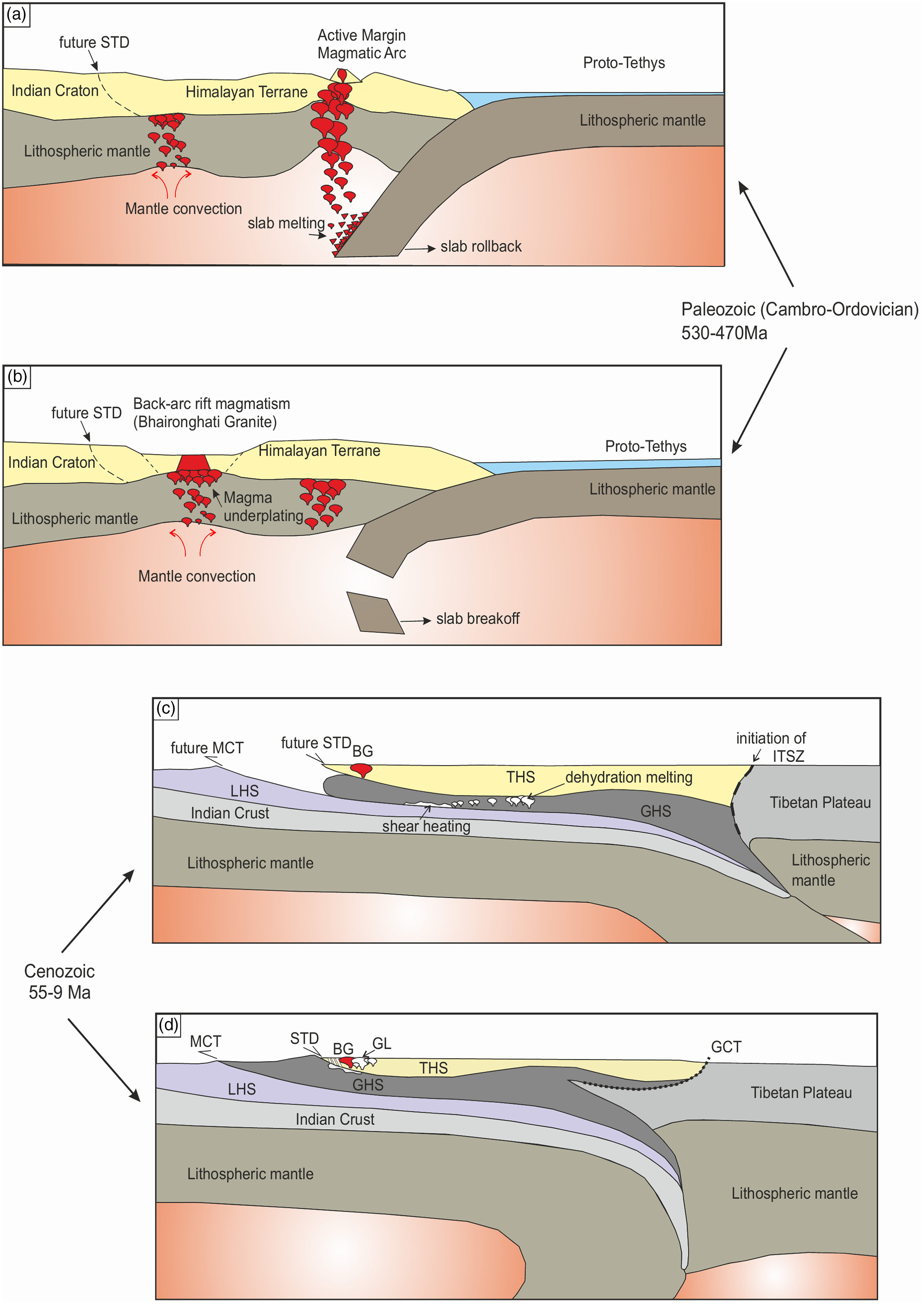
Fig. 10. Cartoon showing different stages of orogeny build-up and related magmatism involved in the pre- and syn-Himalayan stages. (a, b) Stages of pre-Himalayan tectonic evolution with involvement of back-arc rift (S-type) magmatism in the Palaeozoic. Following the initial mafic magma underplating and generation of initial magmatic arc, high heat flow and eventual melting of the crust led to formation of a back-arc environment between ~530 and 500 Ma, which triggered the emplacement of BG and other equivalent Palaeozoic magmatic rocks (modified after Guo & Wilson, Reference Guo and Wilson2012). (c, d) Cenozoic deformation, magmatism and related metamorphism in exhumation of the GHS and related GHL during the Himalayan orogeny. The Gangotri Leucogranite (GL) is a result of muscovite-dehydration melting of the lower crust, with the possible reason for generation and emplacement of this silicic melt being flexural bending in relation to the steepening of the subducted Indian lithosphere, which caused reheating of the Indian lithosphere below Himalaya (modified after King et al. Reference King, Harris, Argles, Parrish and Zhang2011; Gou et al. Reference Gou, Zhang, Dong, Xiang, Ding, Tian and Lei2016).
Pre-Himalayan Palaeozoic deformation and metamorphism have been studied in some parts of the Higher Himalaya, especially in the Nepal Himalaya (Gehrels et al. Reference Gehrels, DeCelles, Ojha and Upreti2006 a, b). These studies suggest deformation and metamorphism of pelitic rocks in Palaeozoic times and syn- to post-deformation emplacement of Palaeozoic granites. In the present study area, the BG is associated with the low-grade THS or the Harshil Group of rocks with a tectonic/mylonitized contact. U–Pb geochronology suggests an imprint of ~550 Ma ages within the THS (probably during emplacement of BG), while BG is Palaeozoic with very little inherited zircon of Paleproterozoic and Neoproterozoic ages. We infer that the ~550 Ma zircon population within the THS indicates that, as a host body, the THS may have been affected by the Palaeozoic magmatism and emplacement of the BG, at least along the periphery of the BG.
6.c. Age and geochemical characteristics of the Gangotri Leucogranite: implications for the Cenozoic tectonics and magmatism
The Cenozoic Leucogranites are found along-strike the entire Himalayan range, occurring generally on the footwall or the immediate hanging-wall side of the STD and within the THS. These leucogranites vary in age from ~30 Ma to ~7 Ma (Yin, Reference Yin2006 and references therein; Sen et al. Reference Sen, Chaudhury and Pfänder2015 and references therein). They generally either form a discontinuous chain of sills and dykes or are present as laccoliths. Subsequently, they exhumed and were exposed adjacent to the STD, separating the GHS from the low-grade to pristine THS (Scaillet et al. Reference Scaillet, France-Lanord and Le Fort1990, Reference Scaillet, Holtz, Pichavant and Schmidt1996; Harris & Massey, Reference Harris and Massey1994; Searle, Reference Searle1999).
Our geochemical analyses reveal that GL is a product of melting of the upper crust. The Gangotri Leucogranites have considerably high Al2O3, Na2O, P2O5 and Rb contents, and lower Fe2O3, MgO, CaO, K2O, TiO2, Ba, Sr, Th, Zr and Y contents at a fixed SiO2 content which signify lower abundance of mafic minerals. Low FeO (t) and MgO indicate their insignificant contribution in the crystallization and fractionation processes (Figs 5a, 6) (Scaillet et al. Reference Scaillet, Holtz, Pichavant and Schmidt1996; Singh et al. Reference Singh, Mukherjee, Jain, Khanna, Sain and Kumar2003; present study). The P2O5 range at a given SiO2 content is very narrow, suggesting a negligible to very low amount of apatite crystallization (Fig. 6; Stern et al. Reference Stern, Kligfield, Schelling, Fruta and Virdi1989; Manickavasangam et al. Reference Manickavasagam, Jain, Singh, Asokan, Macfarlane, Sorkhabi and Quade1999). Similarly, the primitive-mantle normalized diagrams (Fig. 5a) reveal a negative Zr anomaly, indicating a moderate degree of partial melting of the felsic source. Considering the Rb/Sr vs Ba plots (Fig. 4d), it is inferred that the GL formed as a result of fluid-absent incongruent partial melting by muscovite-dehydration processes. Most of the Greater Himalayan Leucogranites along-strike the Himalaya are a result of muscovite vapour-absent melting reactions. This process generally requires a decrease in pressure conditions which could have been obtained during rapid exhumation and subsequent erosional processes (Clemens & Vielzeuf, Reference Clemens and Vielzeuf1987; Harris & Massey, Reference Harris and Massey1994; Scaillet et al. Reference Scaillet, Holtz, Pichavant and Schmidt1996; Searle, Reference Searle1999; Guo & Wilson, Reference Guo and Wilson2012; Gou et al. Reference Gou, Zhang, Dong, Xiang, Ding, Tian and Lei2016) (Figs 4d and 5a).
U–Pb dating of zircon from a representative sample of GL (sample G1) yielded a crystallization age of 21.73 ± 0.011 Ma. This age is contemporaneous with most of the leucogranites from the Western Himalaya (cf. Yin, Reference Yin2006 and references therein; Sen et al. Reference Sen, Chaudhury and Pfänder2015 and references therein; Horton et al. Reference Horton, Lee, Hacker, Bowman-Kamaha’o and Cosca2015; Weinberg, Reference Weinberg2016; Montemagni et al. Reference Montemagni, Carosi, Fusi, Iaccarino, Montomol, Villa and Zanchetta2020).
Previous studies have defined the leucogranite magmatism as a product of intense crustal melting related to the N–S extension-induced normal fault system (JNF/STD) (Guillot & Le Fort, Reference Guillot and Le Fort1995; Carosi et al. Reference Carosi, Lombardo, Molli, Musumeci and Pertusati1998; Zhang et al. Reference Zhang, Harris, Parrish, Kelley, Zhang, Rogers, Argles and King2004, Reference Zhang, Harris, Parrish, Zhang, Zhao and Li2005; Xu et al. Reference Xu, Yang, Qi, Cui, Li and Chen2006). The leucogranites are differentiated as GHL (Greater Himalayan Leucogranites) and THL (Tethyan Himalayan Leucogranites) on the basis of their geochemical and isotopic characteristics (King et al. Reference King, Harris, Argles, Parrish and Zhang2011; Guo & Wilson, Reference Guo and Wilson2012). These leucogranites were emplaced from south (GHL) to north (THL) following the progressive northward thrusting of the Indian subcontinent following the initiation of India–Asia collision along with two-component mixing in the source region between the GHS and fluids derived from underlying LHS. Gou et al. (Reference Gou, Zhang, Dong, Xiang, Ding, Tian and Lei2016) predicted a ~15–20 % melt production for the pelitic schists and orthogneisses of the GHS. Melt thus produced was sufficient for formation of GHL and THL. GHL is mostly tourmaline–muscovite leucogranites, whereas THL is a two-mica leucogranite. This suggests that the GHL and THL have different crystallization temperatures and were the product of separate dehydration melting reactions.
Our study reveals that the Gangotri Leucogranites have high Rb/Sr ratios, negative correlation of Ba content with the Rb/Sr ratios, low Sr/Ba ratios and distinct Eu anomalies (Fig. 5a; Table 2). Hence, these leucogranites are the product of muscovite-dehydration melting, and can be classified as the GHL (Scaillet et al. Reference Scaillet, Pêcher, Rochette and Champenois1995; Singh, Reference Singh2018; present study). According to Guo & Wilson (Reference Guo and Wilson2012), underthrusting of the Indian subcontinent during post-India–Asia collision (~55 Ma) resulted in metasomatism of the GHS sequence with mixing of fluids from LHS that led to generation of leucogranite magmas with phases of decompression and reheating (25–9 Ma). Flexural bending in relation to the steepening of the subducted Indian lithosphere caused reheating of the Indian lithosphere below the Himalaya due to upwelling of asthenospheric mantle. This formed a zone of N–S extension (JNF/STD) along which the Cenozoic leucogranites were emplaced (Fig. 10c, d). Furthermore, the devolatilizing muscovite reactions might have reduced the viscosity by producing a moderate percentage of in situ partial melt. This is evident on the initiation of magmatism and later exhumation-controlled development of the migmatite zone at higher structural heights of the GHS and within many parts of the Himalayan hinterland (Patiño Douce & Harris, Reference Patiño Douce and Harris1998; Gou et al. Reference Gou, Zhang, Dong, Xiang, Ding, Tian and Lei2016; Singh, Reference Singh2018).
6.d. Significances of concentration of Th and U and their ratios
The concentrations of heat-producing elements (U, Th and K) have a significant effect on the magmatic and tectono-metamorphic evolution of the crust. With the onset of crustal anataxis, the growth, breakdown and partitioning of Th and U into accessory minerals affect the crustal differentiation process. The GL and BG are high-T melt products, and equilibrium concentrations of Th, U, K and LREE in these rock bodies provide a hint as to the chemical composition of the lower and middle crust from which the melt evolved (Villaseca et al. Reference Villaseca, Martín Romera, De la Rosa and Barbero2003; Yakymchuk et al. Reference Yakymchuk, Kirkland and Clark2018; Yakymchuk & Brown, Reference Yakymchuk and Brown2019). From the geochemical analysis of GL and BG and the low-grade sedimentary THS, it is inferred that the distribution of LREE, Zr and P in the rock-forming minerals during crustal melting and anataxis may significantly affect the partition of heat-producing elements (Bea, Reference Bea2012). Geochemical analysis (Figs 4, 5) and Th/U ratios of sedimentary THS and GL and BG suggest concentration of K and U decreases with increasing temperature, whereas concentration of Th slowly increases (Fig. 9c). Furthermore, it is observed that most of the zircon analyses from GL and BG have Th/U ~1 or >1; whereas Th/U ratio < 1 in zircon from THS and THS-hosted leucocratic dyke. It can be inferred that GL and BG are completely hosted by igneous zircon and any kind of kinetic restrictions on dissolution of Th and U, or distribution coefficients between zircon, apatite and melt, may significantly affect the partitioning of Th and U into melt production. From our observations, it can be argued that the relative increase in Th/U ratio for GL and BG may either be caused by preferential breakdown of U-rich accessory minerals, or precipitation of high Th/U accessory minerals in the source melt during emplacement. Furthermore, the retention of Th and U by GL and BG, both mid-crustal melt derivatives, suggest that retention of heat-producing elements may be responsible for the generation of radiogenic heat during crustal melting, as heat provided by lithospheric mantle is limited and insufficient to cause melting and exhumation.
6.e. Relationship between leucocratic dykes and the Gangotri Leucogranite
The batch of leucocratic dykes (L1), appearing on the immediate hanging wall of the JNF in the Tethyan metasedimentary rocks (THS), is different from the GL in terms of itsmineralogy and texture. Earlier workers suggested that this set of leucocratic dykes is characteristically a part of the Gangotri Leucogranite as it has almost the same mineralogy and texture. It is also suggested that these dykes are more refracted in nature, representing an over-saturated part of the same melt upwelling (Scaillet et al. Reference Scaillet, Pêcher, Rochette and Champenois1995; Sorkhabi et al. Reference Sorkhabi, Stump, Foland, Jain, Jain and Manickavasgam1999; Searle, Reference Searle1999; Singh et al. Reference Singh, Mukherjee, Jain, Khanna, Sain and Kumar2003). Our study shows that the leucocratic dykes are mineralogically different than the GL as they contain a small amount of sillimanite with large blebs of tourmaline along with over-saturation of silica. Geochemical analyses of the leucocratic dykes associated with the THS host rock suggest that their composition is highly silicic (SiO2 = 74.44–75.6 wt %), and sodic (Na2O = 5.54–5.6 wt %). Moderate enrichment of light REE and strong Eu anomaly characterize these dykes (Figs 5, 6; Table 2). These leucocratic dykes have lower ∑REE, lower CaO, K2O and equivalent Fe2O3 contents. The leucocratic dykes also have very low Sr, Ba, Zr contents and also less Sr/Y, Zr/Hf ratios, but high Rb concentrations and Rb/Sr ratios along with their highly peraluminous nature (Fig. 5). The Rb/Sr vs Ba (Fig. 4d) suggests that the dykes are a result of muscovite-vapour present reaction conditions. The probable reason is that K-feldspar from the immediate footwall of the JNF along with quartz and plagioclase from the THS host rock body might have participated in the production of the melt in the water-saturated and vapour-present conditions (Scaillet et al. Reference Scaillet, Pêcher, Rochette and Champenois1995). The dehydration-melting solidus for muscovite-bearing rocks has a smaller dP/dT slope. Hence, a protolith of muscovite-bearing schist undergoes decompression melting more readily, suggesting that muscovite is a deep crustal H2O reservoir (Patiño Douce, Reference Patiño Douce1997; Patiño Douce & Harris, Reference Patiño Douce and Harris1998; Patiño Douce & McCarthy, Reference Patiño Douce, McCarthy, Hacker and Liou1998). Dehydration melting of metapelites during adiabatic compression (6–8.5 kbar, 750–850 °C) is attributed to the generation of leucogranitic magmas in the Himalaya.
Zircon U–Pb LA-MC-ICP-MS geochronological analyses indicate that the zircon hosted within these leucocratic dykes is mostly inherited. Geochronological data from sample L1 reveal a wide scattering of age between ~550 and 1700 Ma, with the most prominent peak at 930 Ma (Fig. 8b). Such a striking similarity in the age-peaks from both samples T2 and L1 suggests that the zircon of L1 is basically part of the THS host-rock body that may have been incorporated into the melt as a result of wall-rock assimilation. The melt, from which this set of leucocratic dykes was produced, was too refracted to produce any zircon from the melt during the formation of the dykes.
Furthermore, regarding the possible sources of the leucocratic dykes on the immediate hanging wall of the JNF, it can be argued that the Bhaironghati granite cannot be one as it shows no signature of deformation or partial melting. The THS, despite being the host rock, is unlikely to be a source, as its metamorphic grade is too low to produce partial melts and finally over-saturated leucocratic dykes. Ascent and emplacement of granitic rocks, especially a highly silicic leucocratic variety like these dykes, will require the assistance of regional deformation that would create space for the highly viscous leucocratic melt to ascend and emplace (Rosenberg et al. Reference Rosenberg, Berger and Schmid1995; Vigneresse et al. Reference Vigneresse, Tikoff and Améglio1999). We opine that these leucocratic dykes are highly refracted parts of the Gangotri Leucogranite that migrated and emplaced along extensional fault zones related to the JNF/STD. Since the BG is a massive and compact pluton devoid of any structural anisotropy, this highly viscous leucocratic melt could not penetrate the BG pluton and was only observed within the weaker and foliated THS.
7. Conclusions
-
1. The Jhala Normal Fault (JNF)/STD marks the onset of the THS and shows top-to-the-NE extensional shear with some amount of top-to-the-S compressive shear, which appears to be older.
-
2. The Bhaironghati Granite (BG) is an S-type two-mica granite and a product of pre-Himalayan Palaeozoic magmatism owing to extensional tectonics in a back-arc or rift setting.
-
3. The Gangotri Leucogranite (GL) is a result of muscovite-dehydration melting of the lower crust. The possible reason for generation and emplacement of this silicic melt may be flexural bending in relation to the steepening of the subducted Indian lithosphere which caused reheating of the Indian lithosphere below Himalayan orogen.
-
4. The leucocratic dykes present within the THS are highly refracted parts of the Gangotri Leucogranite that migrated and emplaced along extensional fault zones related to the JNF/STD.
Supplementary material
To view supplementary material for this article, please visit https://doi.org/10.1017/S0016756821000789
Acknowledgements
Director WIHG is thanked for his encouragement and support. AK Singh and Saurabh Singhal are thanked for bulk rock geochemistry and U–Pb geochronological analysis. This work is part of the first author’s doctoral research work in the Bhagirathi Valley. Christopher Spencer and an anonymous reviewer are thanked for constructive reviews. Sheila Sherlock is thanked for editorial handling and helpful suggestions.


