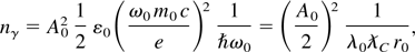
2. COMPTON SCATTERING THEORY
This section is intended as an overview of some of the salient
features of Compton scattering, in the linear regime; for more
information, the reader should consult Hartemann et al. (2001) and Hartemann (2002). The linear regime corresponds to small laser
radiation pressures, where the normalized vector potential satisfies
the condition
In this situation, the electron motion in its original rest frame is
a simple transverse oscillation at the Doppler-shifted laser frequency,
and it radiates as a dipole. In Eq. (1), Aμ =
(φ,A) is the 4-potential of the laser wave, e is
the charge of the electron, m0 its rest mass, and
c is the speed of light. As the electric field can be
expressed as
it is easily seen that for a monochromatic wave of pulsation
ω0, and in the Coulomb gauge, we have
where E0 is the characteristic strength of the
laser electric field.
The physical interpretation of the normalized vector potential is
straightforward: On the one hand, considering a monochromatic plane
wave of wavelength λ0, the energy density is
on the other hand, this quantity can be interpreted in terms of
photon density, and we have
Here, ε0 is the permittivity of vacuum. Using the
definition of the normalized vector potential, we find that
where we have introduced the electron reduced Compton wavelength,
,
and the classical electron radius,
;
here, α is the fine structure constant. Thus, a simple and elegant
result is obtained: The normalized vector potential is directly related
to the number of photons contained in a cube with a side that is the
geometrical mean of the classical and quantum electrodynamic scale lengths,
and the radiation wavelength.
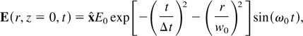
In the specific case of a linearly polarized Gaussian laser pulse,
the electric field at the focal plane takes the form
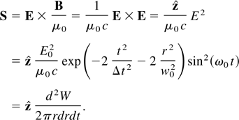
and we can use the Poynting vector S = E ×
H, to evaluate the normalized vector potential: We first
have
Equation (8) can easily be integrated to yield the total energy in
the laser pulse:
Using Eq. (9) and the relation between the normalized potential and
the electric field, we have
Here, w0 is the 1/e2
radius of the laser focal spot, and the intensity at full width at half
maximum (FWHM) of the laser pulse is equal to
;
for visible wavelengths, A0 approaches unity for peak
intensities near 1017 W/cm2.
To derive the well-known Compton formula yielding the energy of the
Doppler-upshifted photons, the correlation between the initial photon
state and the scattered photon 4-wavenumber can be used by considering
the conservation of energy and momentum: We have
which can also be expressed as
after introducing the Compton wavelength,
.
In the above, uμ = (γ,γβ) =
dxμ /dτ is the normalized
4-velocity, and kμ =
(ωc−1,k) is the 4-wavenumber.
In addition, the 4-velocity is normalized, with
uμuμ = −1, and
the photon mass shell condition, or dispersion relation, implies that
kμ kμ = 0. Using the
first condition, we have
which yields
Explicitly developing Eq. (14), we first find that
using the normalization of the 4-velocity, this reduces to
finally, the dispersion relation allows us to eliminate the quadratic
terms in kμ kμ, to
obtain the sought-after relation between the initial and final photon
states:
In vector form, this result can be expressed as
In the case where recoil is negligible, we have
,
and we recover the well-known Thomson scattering result:
We can define the incidence angle, φ, and the scattering angle,
θ, to recast Eq. (19) as
The differential scattering cross section can be derived by starting
in the rest frame of the electron and boosting back to laboratory
frame; the main steps of the derivations are outlined here. In the
Thomson scattering limit, the incident photon has a very small energy
compared to the electron rest mass; hence, the scattered photon has the
same energy as the incident photon in the electron rest frame. For the
case of an electron distribution at rest, the total number of scattered
photons per unit time is simply the overlap integral of the product of
the total Thomson cross section multiplied by the flux of incident
photons, leading to
where σ is the total Compton scattering cross section, and
nγ′(r,t) and
ne′(r,t) are,
respectively, the photon and electron density in the electron beam rest
frame. To generalize this for a relativistic electron beam, we note
that that the total number of scattered photons is invariant under a
Lorentz transformation, and that the above expression can be expressed
in covariant form as the integration of the product of the electron
4-current density, jμ =
ne ecuμ, and the
photon 4-flux, φμ = cnγ
kμ, which yields
In the case of a single electron, the density is a delta-function:
ne(r,t) =
δ[r −
re(t)] , where
re(t) describes the electron
trajectory. Thus, the rate of scattered photons by a single electron
becomes
Likewise, the rate of photons scattered into a given solid angle is
given by
while the rate scattered per unit frequency is given by
where dσ/dΩ is the differential
scattering cross section, ωs is angular
frequency of the scattered photon, and
is the relativistic Doppler upshift of the scattered photon, defined in
Eq. (19), which depends on the angle of incidence, φ, and the
scattering angles, θ, between the observation direction and the
electron direction. Equation (25) completely describes the temporal,
spectral, and spatial properties of the scattered X-ray
distribution.
A general, covariant expression for the differential cross section in
Eq. (25) can be derived by first transforming the wave vector of
incident photon into the electron rest frame. The corresponding rest
frame differential cross section can then be transformed back into the
laboratory frame. If we represent the incident laser polarization
vector in the electron rest frame as α′, the
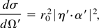
differential cross section is given by the simple expression
where η′ is the scattered photon polarization, and
r0 is the classical electron radius.
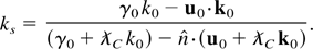
Using the angular notation defined in Figure
1, and summing over final polarization states yields the Compton
scattering cross section, as expressed in the initial rest frame of the
electron, for an arbitrary linearly polarized incident photon:
Compton scattering interaction geometry in the electron rest
frame.
To make Eq. (27) practical, it is desirable to express the components
of the rest frame incident laser polarization vector in terms of
laboratory frame coordinates. In addition, to facilitate the inclusion
of three-dimensional (3D) effects resulting from the focusing of the
electron and laser beams, the direction of the individual electrons and
photon wave vectors in the each beam are assumed to deviate slightly
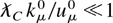
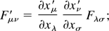
from the average directions defined above. As shown in Figure 2 (top), the direction of each incident
photon wave vector will be specified by an additional rotation
ξx about the y-axis, and a rotation
ξy about the x-axis. Likewise, an
electron laboratory frame, with Cartesian coordinates
(xe,ye,ze)
is defined such that the ze-axis is
collinear with the individual electron direction; this frame is
specified by a rotation ξxe about the
ye-axis and an angle
ξye about the
xe-axis, as shown in Figure 2 (bottom).
Top: Illustration of the laser incident direction and polarization.
α is the direction of the polarization vector of the
laser, where φp represents the rotation angle
of α about the zL-axis.
Bottom: Illustration of the electron incident direction. The electron
beam is incident along the z-axis, but the direction of each
electron deviated by the angles specified by
ξxe and
ξye.
To simplify the Lorentz transformations to and from the electron rest
frame, our approach is to first calculate the cross section in a
laboratory frame aligned with the electron velocity, then rotate back
to the laboratory frame, which is generally chosen so that the laser
focus is the origin, while the direction of propagation of the laser
pulse and its polarization, in the linear case, can be used to define
its axes. To Lorentz transform the components of the polarization
vector, we use the transform of the electromagnetic field tensor:
we then extract the polarization vector by noting that, in general,
α = E/|E|. After
lengthy algebra, we obtain:
Equation (29) expresses the normalized components of the polarization
vector in the electron beam rest frame in terms of the laser and
electron direction, the electron beam energy, and the laser
polarization. Note that in the plane wave approximation, where
ξx = ξy = 0, Eq. (29)
reduces to
Equation (29) can now be transformed to the electron laboratory frame
described above by considering the Lorentz transform of the
4-wavenumber, kμ. Within this frame, the
scattered photon direction is defined by the wave-vector
where θe′ and
φe′ specify the scattered photon
direction about the positive z-axis in the rest frame, as
shown in Figure 1. Because we are primarily
interested in the Thomson scattering limit, the scattered photon
frequency, ωs′, is taken to be equal to
the incident frequency ω0′. The scattered photon
energy in the rest frame, ωs′, is
expressed in terms of the photon energy in the lab frame,
ωs, by using the Lorentz transformation once
again, from the laboratory frame to the rest frame:
where θe is the angle of the scattered
photon with respect to the ze-axis in the
electron laboratory frame. Applying the Thomson scattering limit
approximation and using Eq. (32) leads to
For a head-on collision, we recover the well-known photon maximum
Doppler upshift of approximately 4γ2, whereas for a
90° collision, the upshift approaches 2γ2.
Furthermore, the variation of the scattered photon energy as a function
of the observation angle, θe, can be
approximated by a Lorentzian with a FWHM equal to 1/γ.
Finally, the propagation direction of the scattered photon, as
measured in the rest frame, can be expressed in terms of laboratory
angles by transforming ks back. In
addition, we will use the fact that
where, dΩ = sin(θ)dθdφ
= −d cos(θ)dφ, and where we have used
the fact that for the case under consideration, dφ =
dφ′. This leads to the sought-after expression for
the differential cross section in the laboratory frame:
At this point, a three-dimensional time and frequency-domain model of
the scattering process can be developed by considering the phase-space
photon density of the focusing laser pulse, which can be derived using
Fourier analysis and the paraxial wave approximation (Hartemann et
al., 1998, 2001; Hartemann, 2002).
The laser frequency spectrum provides the incident photon energy
distribution, whereas the transverse momentum distribution is obtained
by rescaling the transverse wave number spectrum of the focusing wave
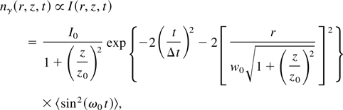
by a factor ħ. The three-dimensional spatial photon density is
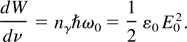
proportional to the intensity of the laser pulse, given by
for a cylindrical focus and a linearly polarized wave;
〈sin2(ω0 t)〉 = 1/2.
Finally, for a Fourier-transform limited pulse, which corresponds to
the minimum uncertainty according to the Heisenberg Principle, the
photon phase space conjugate coordinates are uncorrelated.
Most of the theoretical results and analyses presented in this
article result from a three-dimensional time and frequency-domain code
based on the formalism described above, and from a three-dimensional
frequency-domain code described in Hartemann et al. (2001), which uses the Hartemann–Le Foll (HLF)
Theorem.
The HLF Theorem will be used here to describe some of the important
features of Compton scattering in the case of an electron beam with
energy spread and emittance.
The HLF Theorem states that in the linear regime, where the
4-potential amplitude satisfies the condition
eA/m0 c << 1, and in
the absence of radiative corrections (Dirac,
1938; Hartemann & Kerman, 1996;
Hartemann, 1998), where the frequency cutoff
is ω << m0
c2/ħ, as measured in the electron frame,
the spectral photon number density scattered by an electron interacting
with an arbitrary electromagnetic field distribution in vacuum is given
by the momentum space distribution of the incident vector potential at
the Doppler-shifted frequency:
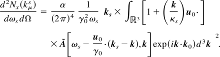
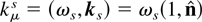
Here,
is the 4-wavenumber of the wave scattered in the observation direction
,
at the frequency ωs; α =
e2/2ε0 hc ≃
1/137.036 is the fine structure constant;
uμ0 =
(γ0,u0) is the electron initial
4-velocity; xμ0 = (0,
x0) is its initial 4-position; and we have
introduced the scattered light-cone variable,
κs =
−u0μkμs
= γ0ωs −
u0·ks. The term
[1 +
(k/κs)u0·]
is to be considered as an operator acting on the Fourier transform of
the spatial components of the 4-potential, Aμ =
(V, A),
while the term
exp(ik·x0) gives rise to
the coherence factor (Hogan et al.,
1998; Hartemann, 2000).
We now consider the case of a linearly polarized plane wave with an
arbitrary temporal profile: The 4-potential is
,
where φ =
−kμ0xμ,
and kμ0 = (1,0,0,1), for a wave
propagating along the z-axis. Introducing the temporal Fourier
transform of the pulse envelope,
,
we have
where δ(ω − kz)
corresponds to the pulse propagation, and
is the spectrum of the pulse, centered around the normalized frequency
ω0 = 1, in our units. Applying the HLF Theorem, we
immediately find
where
.
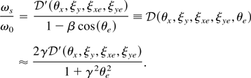
Introducing the normalized Doppler-shifted frequency
,
and the differential scattering cross section, or radiation pattern,
,
this result can be recast as
2.1. The one-dimensional cold spectral density
In the case of a Gaussian pulse envelope, where
g(t) =
e−t2/Δt2,
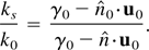
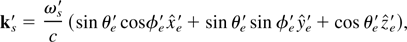
and for the interaction geometry shown in Figure
3, Eq. (41) takes the familiar form
Here, φ is the incidence angle between the initial electron
velocity and the direction of propagation of the plane wave, and θ
is the scattering angle, measured with respect to the electron initial
velocity. Equation (42) clearly shows that the scattering spectral
density is proportional to the incident photon number density, as
represented by the laser intensity
A02Δφ, and that the cold
spectral bandwidth of the X rays is given by that of the incident laser
pulse, Δφ−1 = 1/ω0
Δt. Equation (42) also indicates that the peak intensity
is radiated near the Doppler-shifted frequency, where
χ(ωx,γ0,θ,φ)
≃ 1; this yields
For a head-on collision, where φ = π, the frequency radiated
on-axis, for θ = 0, is the same as the well-known free-electron
laser (FEL) frequency for an electromagnetic wiggler (Roberson & Sprangle, 1989): For
ultrarelativistic (UR) electrons, we recover the well-known relation,
ωx = γ2(1 + β)2
≃ 4γ2.
Schematic of the three-dimensional Compton scattering geometry used
for the frequency-domain code.
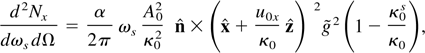
The angular X-ray energy distribution can be mapped by considering
the position of the spectral peak, where ωs =
ωx and χ = 1. We then find that
in the particular case of a head-on collision (φ = π), the
angular behavior reduces to
where the approximation holds for small angles; the FWHM of the X-ray
cone can be derived by further simplifying Eq. (44) for UR electrons
and small angles, where we can use the following approximations:
u(γ) ≃ γ − (1/2γ), and cos θ
≃ 1 − (θ2/2), respectively. With this,
the angular energy distribution is described by a Lorentzian:
1/[1 + (γθ)2] , which has an angular
FWHM equal to 2/γ. This well-known behavior of the X-ray
frequency-integrated cone (Zholents & Zolotorev,
1996; Schoenlein et al.,
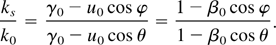
2000) is illustrated in Figure 4,
where the correlation between the spectral density and the angle is
manifest.
False color plot of the spectral density of scattered X rays in the
y–z plane resulting from the head-on collision
of a 50-MeV electron bunch with εnx = 1
mm·mrad focused to an rms spot size of 20 μm with an 800-nm,
1-ps bandwidth laser pulse polarized in the
x-direction.
Before studying the effect of energy spread and emittance (Carlsten, 1989; Reiser,
1994; Wiedemann, 1999), we also note
that the cold, average on-axis brightness of the X-ray source can be
estimated by multiplying the spectral brightness by the normalized
average electron bunch current
〈Ib〉 = qρ, where
ρ is the repetition rate of the system; by considering a 1
mrad2 solid angle, ΔΩ = 10−6, and
a 0.1% fractional bandwidth, Δω = ωx
× 10−3; and by normalizing the source size to 1
mm2; with this we obtain
where 〈Bx〉 is expressed in
units of photons/(0.1% bandwidth × mrad2 ×
mm2 × s), and rb is the
electron beam spot size, which we assume to be equal to the laser spot
size. The normalized vector potential is given by Eq. (10) as expressed
in terms of the laser pulse energy
,
duration Δt, frequency ω0, and focal spot size
w0. With this, the main scaling laws for the X-ray
brightness, in the case of an electron beam with no emittance, are
clearly exhibited: bilinear in the laser pulse energy and electron
bunch charge, and inversely proportional to the 4th power of the source
size,
1/w02rb2.
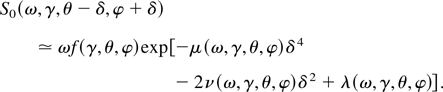
2.2. Energy spread
The formalism used to model the influence of the electron beam phase
space topology is now illustrated in the case of a linearly polarized
plane wave with an arbitrary temporal profile; in this simple case,
analytical results are derived. We introduce the cold, one-dimensional
(1D) normalized spectral brightness,
Note that as S0 is a function of the electron
initial energy, γ, scattering angle, θ, and incident angle,
φ, we can perform incoherent summations over the electron initial
energy and momentum distributions to study the effects of energy spread
and emittance. For conciseness, the scattered frequency is now labeled
ω, and the initial electron 4-velocity is labeled as
uμ0 = (γ,u), were
.
The use of incoherent summations, although intuitively obvious, can be
rigorously justified as shown in Hartemann (2000).
We start with the beam energy spread; the “warm” beam
brightness is given by
where we have used a Gaussian distribution to model the beam
longitudinal phase space. Note that as
the cold brightness is automatically recovered for a mono-energetic
electron beam.
The analytical result in Eq. (47) is obtained by Taylor expanding to
second order around the central electron energy, γ0. The
normalization constant is given by
an excellent approximation for γ0 >> 1 and
Δγ/γ0 << 1. Here, Δγ refers to
the energy spread; in addition,
Because v and w are both linear functions of which
is equal to zero at the peak of the X-ray spectrum, the exponential is
equal to one for ω = ωx. In addition, the
factor
[Δφ(Δγ/γ0)]2
in the square root shows that the relative energy spread must be
compared to the normalized laser pulse duration, which is equivalent to
the number of electromagnetic wiggler periods; this indicates that to
increase the X-ray spectral brightness by lengthening the drive laser
pulse, the requirement on the electron beam energy spread becomes
increasingly stringent. Figure 5 illustrates
the effects of energy spread, which are seen to symmetrically broaden
the scattered X-ray spectrum and lower the peak intensity.
A low energy, high repetition rate example, illustrating the broad
potential capabilities of Compton scattering X-ray sources. On-axis
X-ray spectral brightness for a cold beam (blue, right scale),
Δγ/γ0 = 0.5% (green), ε = 1
π-mm·mrad (red), and three-dimensional computer simulations
(red squares). The beam energy is 22.75 MeV, the bunch charge is 0.5
nC, and its duration is 1 ps; the laser wavelength is λ0
= 800 nm (Ti:Al2O3), the laser pulse energy is 50
mJ, w0 = rb = 10
μm cylindrical focus, φ0 = 180°,
A0 = 0.17, and the overall repetition rate of the
system is 1 kHz. The synchrotron units correspond to photons/(0.1%
bandwidth × mm2 × mrad2 ×
s).
2.3. Emittance
We now turn our attention to the influence of the electron beam
emittance:
where the spread of incidence angle is given in terms of the beam
emittance ε, and radius rb, by
Δφ = ε/γ0
rb, and where φ0 is the
mean incidence angle, defined by the laser and electron beams. Again,
the normalization constant is given by
provided that Δφ << 1.
In Eq. (49), we note the important geometrical correction term,
θ − δ, which corresponds to the fact that the scattering
angle is measured with respect to the initial electron velocity. The
effect of emittance are illustrated in Figure
5, and are found to be independent of φ0.
Considering the on-axis X-ray spectral line, it is clear that emittance
both asymmetrically broadens the spectrum and decreases the peak
spectral brightness; near head-on collisions, a low energy tail
develops because the maximum Doppler shift corresponds to δ ≃
0: Other electrons produce a smaller upshift, thus contributing to the
lower energy photon population seen in Figure
5.
Returning to the cold, one-dimensional spectral brightness, the
integral over a Gaussian distribution of incidence angle can be
performed analytically, provided that the spectral density is
approximated by the exponential of a biquadratic polynomial (Gradshteyn
& Ryzhik, 1980, Eqs. 3.923, 3.924, and
3.323.3):
where K1/4 is defined in terms of Bessel
functions of fractional order
Because ωf(γ,θ,φ) is a slow-varying
function of the incidence angle, we can seek an approximate expression
for the cold spectral density of the form
The constant term is obtained by taking δ = 0 :
λ(ω,γ,θ,φ) =
−(Δφ2/2)[χ(ω,γ,θ,φ)
− 1]2; the other coefficients are derived using
cos δ ≃ 1 − (δ2/2!) +
(δ4/4!), and sin δ ≃ δ −
(δ3/3!). We then find that
with
This result is compared to a full three-dimensional numerical
simulation in Figure 5; the agreement is
excellent. Note that to include both the effects of energy spread and
emittance, the analytical results given in Eqs. (51) and (53) are
multiplied by the energy spread degradation factor, as measured at the
peak of the cold spectrum:
To summarize, we find that the spectral brightness, which is a
delta-function for a single electron, is broadened by a number of
factors: First, the finite laser pulse bandwidth yields a minimum
spectral width, as the electron beam is illuminated by a photon
distribution containing different colors; next, the energy spread of
the electron beam also contributes to the broadening of the X-ray
spectral brightness because the different electron energies translate
into varying Doppler upshifts; finally, emittance contributes an
asymmetric broadening toward low X-ray energies due to the tilt
distribution of the X-ray cones radiated by the focusing electrons:
Part of the on-axis radiation is actually contributed by lower energy
photons radiated off-axis by electrons with finite transverse velocity.
We also note that the three-dimensional focusing of the laser further
increases the width of the X-ray spectrum by contributing a
distribution of incidence angles. The X-ray phase space is a
convolution of both the electron and laser beams phase space.
3. EXPERIMENTAL SETUP
The PLEIADES facility comprises three major subsystems: a TW-class
CPA laser, a high-brightness electron linear accelerator, and the X-ray
interaction region and diagnostics. In this section, each subsystem is
described in detail, and their performance is assessed within the
overall context of a bright, picosecond, tunable, hard X-ray source.
The overall experimental repetition rate of the system is 10 Hz, and is
limited by the available average pump power for the various lasers used
at PLEIADES.
3.1. Laser system
The main laser system used for these experiments, which is known as
the FALCON laser, is a Ti:Al2O3 CPA system
capable of producing over 1 J of uncompressed light near 820 nm. The
laser system front end is a compact C20s Ti:Al2O3
oscillator from Femtosource, which produces 30-fs pulses with a
bandwidth of 36 nm centered at 815 nm. This
mirror-dispersion-controlled Kerr-lens mode-locked laser also serves as
the master clock for the entire experimental facility: A photodiode
monitors the output pulse train of the oscillator, and that signal is
compared to a 81.557-MHz reference signal from a stabilized crystal
oscillator in a Time-Bandwidth CLX-1000 timing stabilizer. This box
controls a picomotor and a piezoelectric crystal attached to the end
mirror of the oscillator cavity, and adjusts the cavity length to keep
the oscillator frequency stable. The photodiode signal is also filtered
to produce a sinusoidal waveform that is frequency multiplied in a
phase-locked dielectric resonant oscillator to 2.8545 GHz, which is
then used to drive the rf amplifier and klystrons for the linear
accelerator, ensuring phase locking between the laser and electron
systems.
The oscillator pulses are stretched to 680 ps in an all-reflective
parabolic-mirror based expander (Banks et al., 2000). The
pulse train is then split with a dielectric beam splitter into two
beams, with 30% of the light being coupled into a fiber to seed the
photoinjector laser, and the remaining 70% used to seed the FALCON
laser. Because the same oscillator pulse train seeds both laser
systems, minimal timing jitter between the systems is assured.
In the FALCON laser, the oscillator pulses are amplified to an energy
of 7.3 mJ in a standard linear regenerative amplifier cavity, pumped
with 45 mJ of 532 nm light produced by a frequency-doubled,
flashlamp-pumped, Q-switched Nd:YAG Spectra-Physics GCR-190 laser.
Following the regenerative amplifier is a 4-pass amplifier, which is
pumped with the remaining 212 mJ of light from the GCR-190. The
infrared input into the amplifier is monitored by two cameras, imaging
the near and far field spots of the beam. A closed loop control system
adjusts the pointing and centering of the beam via stepper motors on
two mirrors to maintain alignment into the amplifier. The output energy
of this amplifier is 68 mJ. This beam is then sent into a second 4-pass
amplifier, which also has a closed-loop feedback system to maintain
input alignment. This amplifier is pumped by 2.3 J of 532-nm light
produced by a frequency-doubled, flashlamp-pumped, Q-switched Nd:YAG
Spectra Physics QuantaRay PRO-350 laser as well as a 1-J, 532-nm,
Q-switched Nd:YAG pump laser manufactured by Continuum, and produces
1.2 J of uncompressed IR light.
The amplified light beam is expanded and collimated to a
1/e2 radius of 42 mm; the beam is then relay
imaged over 52 m, using two telescopes, to a vacuum chamber near the
accelerator system, where it is compressed in a double-pass grating
compressor. A frequency-resolved, optically gated GRENOUILLE system
(O'Shea et al., 2001, 2002) is used to measure the compressed pulses at
low power, and yields a pulse length of 54 fs IFWHM, with a relative
phase retrieval error of 0.006, as illustrated in Figure 6. The compressed pulse then propagates 20 m
to the final focusing optics, currently an f:25 off-axis
parabola. The loss through the transport and compressor is 45%, leaving
up to 540 mJ available in the interaction region.
GRENOUILLE measurements of the FALCON laser pulse duration. Top:
Experimental data. Bottom: Retrieved data, with a phase error of 0.006;
the corresponding IFWM of the pulse is 54 fs.
3.2. Linear accelerator
The high-brightness electron beam used to generate X rays at PLEIADES
is produced by the Lawrence Livermore National Laboratory 100-MeV
linear electron accelerator, which has been substantially upgraded to
meet the stringent emittance and timing jitter requirements necessary
for efficient Compton scattering. The most significant upgrade was the
installation of a new photoinjector at the front end of the
accelerator, as an alternative to the preexisting thermionic injector.
In the S-band photoinjector, a high charge (nC), picosecond electron
bunch is produced via the photoelectric effect when a UV laser pulse
illuminates the photocathode. The photoemission threshold for the Cu
photocathode is 266 nm, but this value is significantly relaxed by the
strong Schottky effect induced by the 80–100-MeV/m rf field
applied to the photocathode; indeed, the central wavelength of the UV
beam produced after frequency tripling is only 269 nm, but this is
sufficient to obtain a quantum efficiency varying between 8 ×
10−6 and 2 × 10⁻⁵, depending on
the laser injection phase.
As the UV laser system driving the photoinjector is seeded by the
same laser oscillator used for the FALCON laser, the injection time of
the electrons into the linear accelerator can be synchronized to within
1 ps to both the FALCON laser pulse and the S-band rf fields that
energize the linear accelerator. A second major benefit of the
photoinjector technology is that it allows for electron beams with much
higher current densities. For a given extracted charge, this gives a
much smaller initial spot, and a correspondingly lower emittance, as
well as a high (∼100 A) current. Additionally, the accelerating
gradients in a photoinjector (∼100 MeV/m) are generally much
greater than those in thermionic guns, thus limiting the detrimental
effects of space-charge-induced emittance growth that occur at low
energy, before the beam becomes relativistic.
The photocathode UV laser system was installed as close as practical
to the linear accelerator and seeded through a 50-m, single-mode fiber
with 30% of the light that is split off from the main oscillator pulse.
After coupling and transport losses, the seed light has an average
power of 7.3 mW, or 90 pJ per pulse, which is coupled into a linear
regenerative amplifier cavity. The Ti:Al2O3
crystal in this amplifier is pumped with 50 mJ of 532-nm light from a
frequency-doubled, flashlamp-pumped, Q-switched Nd:YAG DCR-2 laser. The
end mirror leakage of this amplifier is monitored with a fast
photodiode, which provides a trigger timing signal for the streak
camera and other diagnostics, which are discussed later. This system
produces 5.9-mJ IR pulses at 10 Hz. Following the regenerative
amplifier is a bow-tie configuration 4-pass power amplifier, similar to
the two discussed for the FALCON system. The
Ti:Al2O3 crystal is pumped with the 280 mJ of
laser light from the DCR pump that is not sent to the regenerative
amplifier, and amplifies the output of the regenerative amplifier up to
the 90-mJ level. Again, this amplifier has an active pointing and
centering system used to align the regenerative amplifier light pulses
as they are injected into the final amplification stage.
The light from the 4-pass is then sent into a grating compressor. The
pulse is not fully compressed to its transform limit; instead, a UV
pulse length of approximately 3 ps rms is used to illuminate the
photocathode. This is because detailed simulations of the electron beam
in the photoinjector clearly show that the best quality beams, as
evaluated in terms of energy spread and emittance, are produced when
using UV laser pulses with durations of a few picoseconds to generate
photoelectrons. In turn, this results from the Coulomb repulsion of the
electrons, which are initially created at rest: As the laser pulse gets
shorter, the electron density increases until space-charge forces begin
severely degrading the electron beam transverse and longitudinal
emittance. This longer pulse also has the advantage of minimizing the
effects on the laser pulse temporal structure resulting from the
residual cubic phase distortions introduced by the 50-m fiber that
transports the laser oscillator pulse to the UV photocathode laser
system. However, it should also be noted that the broadband nonlinear
frequency tripler used to produce UV from the IR pulses is a
challenging component to optimize because the residual chirp of the
partially compressed pulse introduces distortions that make
phase-matching difficult.
Following compression, the pulse is first frequency doubled in a Type
I BBO crystal, then tripled in a second Type I BBO crystal to 269 nm. A
special wave plate is used between the harmonic crystals, which rotates
the polarization of the second harmonic by a half wave to align it with
the fundamental for sum-frequency mixing. Generally, about 1.2 mJ of UV
light is available; however, to prevent damage to the cathode in the
photoinjector, the system is often turned down to provide only about
500 μJ of light at the tripler output. This UV pulse is then
clipped with an aperture to a diameter of 2 mm to provide a hard-edged
UV spot, which further improves the emittance of the photoinjector. The
aperture plane is relay imaged 50 m to the photoinjector cathode. The
UV pulse width is measured at 3 ps rms with a 500-fs-resolution streak
camera using a multiphoton Au photocathode.
The rf photoinjector used to produce the electron beam for PLEIADES
is based on a 1.6-cell standing-wave geometry (Le
Sage et al., 2001). A pulsed S-band (2.8545 GHz) rf
input with 7-MW peak power and 3-μs duration produces a peak axial
electric field of up to 100 MV/m that accelerates the electrons to
5 MeV. Focusing solenoids are employed in the photoinjector to preserve
the transverse emittance (Carlsten, 1989;
Reiser, 1994; Wiedemann,
1999) of the electron bunch, help match the electron beam into
the accelerating sections, and to implement emittance compensation
(Carlsten, 1989). The gun currently operates
with a more conservative accelerating gradient of 80 MV/m to avoid
any possible damage due to rf arcing, which also leads to lower quantum
efficiency on the photocathode.
The electron bunch charge is determined by the pulse parameters of
the UV laser and the quantum efficiency of the photocathode. The 269-nm
laser pulse is imaged to a 1–2-mm spot on the Cu photocathode,
where the axial rf field is nearly maximal; under these operating
conditions, electrons are produced with a typical quantum efficiency of
approximately 8 × 10⁻⁶ electrons/photon,
which yields an electron bunch charge between 250 and 350 pC, as shown
in Figure 7 (top).
Top: Measurement of the bunch charge extracted from the S-band rf
gun. Bottom: Energy spectrum of the electron beam, measured using a
30° dipole with a dispersion of 0.5%/mm at 60 MeV.
The electron bunch length is a function of the laser pulse duration,
bunch charge, and accelerating voltage, and is typically a few
picoseconds long, although bunch lengths as short as 300 fs have been
measured using coherent transition radiation, by operating at reduced
bunch charge and using velocity compression. As mentioned earlier,
because both the UV photocathode laser, which is directly responsible
for producing the electron bunch, and the FALCON drive laser are seeded
from the same oscillator pulse train, the timing of the electron beam
is well synchronized to the laser pulse that it collides with to
produce X rays.
The beam generated by the photoinjector is then coupled into the
100-MeV linear electron accelerator (Fultz &
Whitten, 1971), where it is accelerated to energies ranging
between 20 and 100 MeV by four 1.8-m, SLAC-type traveling-wave
accelerating sections.
After propagating through the interaction area, as shown in Figure 8, the electron beam is deflected by a
30°-bend dipole magnet that separates the bunch from the scattered
X rays, which propagate in the same direction as the electrons. This
dipole also serves as a spectrometer, yielding detailed measurements of
the electron beam energy and energy spread, which is as low as
Δγ/γ ≃ 0.2%, as shown in Figure
7 (bottom). Following the energy spectrometer, the electron beam
is stopped in a Cu collector that also serves as a calibrated Faraday
cup, providing a measure of the electron bunch charge. The electron
collector is housed in a 10-cm-thick lead enclosure to minimize the
effect of bremsstrahlung on the diagnostics.
Schematic of the interaction region, including some of the laser and
electron beam optics, and diagnostics.
3.3. Interaction region and interaction geometry
Two fundamental interaction geometries can be used to perform Compton
scattering experiments: 180° (head-on) collisions, or 90°
(side-on) interactions. Each approach has its own merits, as discussed
below. The main advantage of a noncollinear geometry is that very short
X-ray pulse lengths can thus be generated: In this case, the duration
of the X-ray flash is equal, to first order, to the transit time of the
laser pulse through the focused electron bunch. By comparison, in a
collinear geometry with an ultrashort (<100 fs) laser pulse, the
X-ray pulse duration is essentially that of the electron bunch,
generally on the order of a few picoseconds. In a 90° interaction,
the duration is a convolution of the laser pulse length and the
electron beam diameter, and is only on the order of a few hundred
femtoseconds.
However, the main disadvantages of a 90° interaction geometry are
a lower X-ray flux, resulting from the fact that, for picosecond
electron beams, the laser pulse only interacts with a small fraction of
the electrons, or the considerably more stringent pointing and timing
requirements. This can be studied more systematically by considering
the variation of the X-ray dose as a function of the timing delay
between the drive laser pulse and the electron bunch for different
interaction geometries, as illustrated in Figure
9. Here, we consider a 100-mJ, 50-fs FWHM, 20-μm FWHM laser
pulse interacting with a 1-nC, 2-ps FWHM, 20-μm FWHM,
5-mm·mrad emittance electron beam, and calculate the dose by
integrating Eq. (21) over time for the laser photon density of a
focusing wave given in Eq. (36) and summing over a distribution of
electrons produced by the code PARMELA. In the case of 180°
collisions, the X-ray dose as a function of delay varies essentially
like the Lorentzian 1/[1 +
(z/z0)2] , which
characterizes the diffraction of the laser beam; for the parameters
quoted above, the FWHM of the X-ray dose produced as a function of the
time between the arrival of the laser pulse and the arrival of the
electron bunch at the focus is Δt = 15 ps, which
corresponds to a Rayleigh length z0 =
cΔ/2 = 2.25 mm, in close agreement with the
theoretical value, z0 =
πw02/λ0, where
.
This effect has been measured and is discussed in Section 4. For the
same beams in a 90° geometry, the dose FWHM is only 2 ps, and
the number of X rays produced drops by a factor of 10; furthermore,
the profile is now Gaussian, reflecting the temporal shape of the
electron bunch. Even at a shallow interaction angle of 172°,
the interaction window drops to 2.3 ps. The much larger interaction
window in the 180° geometry results from the fact that the Rayleigh
range and beta function of the laser and electrons, respectively, are
much longer than the actual bunch lengths. When the beams are
collinear, delay simply translates into a longitudinal motion of the
X-ray source, within the spatial volume defined by the two focusing
ranges; furthermore, in that configuration, all the electrons are
illuminated by the drive laser, provided the transverse beam sizes are
similar, thus maximizing the X-ray dose. Because of the numerous
aforementioned advantages of the 180° interaction geometry, this
configuration was chosen for initial experiments; furthermore, for
head-on collisions, the X-ray pulse duration is governed by the
electron bunch length, which has been successfully compressed down to
300 fs rms; therefore, the 180° interaction geometry does not
create any significant limitations for ultrafast X-ray experiments.
Computer simulations of the X-ray dose as a function of the delay
between the laser pulse and the electron bunch. The parameters used are
as follows: laser pulse duration, 50 fs IFWHM; focal spot size, 20
μm IFWHM; laser pulse energy, 100 mJ; electron bunch duration, 2 ps
FWHM; electron bunch charge, 1 nC; bunch focal spot size, 20 μm
FWHM; normalized emittance, 2 mm·mrad.
The layout of the PLEIADES interaction region is shown in Figure 8. The 480-mJ IR laser pulse is focused off
a 60-in. focal length, 12° off-axis parabolic mirror. The focusing
beam is then directed to the interaction region by a motor-controlled
dielectric mirror, which allows for control of the transverse alignment
of the laser focus at the interaction point. The spot is observed to
have a 1/e2 waist radius of 36 μm (42.2
μm FWHM) along the polarization and a measured
M2 value of 1.6, as shown in Figure 10, whereas the 1/e2
waist radius and M2 are equal to 28 μm and 1.2
across the polarization; the average 1/e2
radius is 32 μm, the average M2 is 1.4. In this
case, the Rayleigh range, which defines the interaction region in a
180° geometry, is 〈z0〉 =
π〈w02〉/λ0〈M2〉
= 2.86 mm. After interaction with the electrons, the laser beam
propagates down the linear accelerator beamline and dumps its energy in
the walls as it expands after the focus.
Measurements of the FALCON laser M2. The spot is
observed to have a 1/e2 waist radius of 36
μm (42.2 μm FWHM) along the polarization and a measured
M2 value of 1.6, whereas the
1/e2 waist radius and M2
are equal to 28 μm and 1.2 across the polarization.
The electron beam is focused by a set of quadrupole magnets with a
magnetic field gradient of up to 15 T/m. To aid alignment at the
focus, two cross-oriented dipole magnets steer the beam into this
composite magnetic lens. Because the off-axis parabolic mirror that
focuses the laser is fixed, the longitudinal position of the
interaction region is set by the laser focus, and the longitudinal
position of the electron beam waist is adjusted to the position of the
laser focus using the electron focusing system. Measurements of the
electron beam at the focus have shown a spot size
σx = σy = 27 μm
rms, a normalized horizontal emittance εx =
3.5 mm·mrad rms, and a normalized vertical emittance
εx = 11 mm·mrad rms, which were
measured using the standard quadrupole scan technique. Typical
measurements are illustrated in Figure 11.
Top: Quadrupoles scans used to determine the emittance of the
electron bunch. In this specific case, the normalized horizontal
emittance is 5 mm·mrad, and the vertical emittance is 13
mm·mrad. Improvements on the beamline tuning have produced
emittances as low as 3.5 mm·mrad horizontally and 11
mm·mrad vertically. Bottom: Optical transition radiation image
of the focused electron beam; σx =
σy = 27 μm rms, at 57 MeV.
Spatial alignment of the two focal spots is performed with the aid of
an optically polished 0.3-in. Al cube. The cube is mounted on a
three-axis translation stage with its faces oriented vertically normal
to the beamline, and horizontally at 45° to the beamline. Because
the laser beam reflects well from the surface, the focus at the surface
of the cube can be imaged into a CCD camera. To avoid damaging the cube
or camera, the IR laser pulse energy is reduced by a combination of
turning off the pump lasers to the two 4-pass amplifiers and inserting
neutral density filters to attenuate the beam by a factor of
108; special care was taken to ensure that this attenuation
process did not significantly steer the laser pulse nor change its
timing delay. When the electron beam strikes the cube, it produces OTR,
which can also be imaged by the CCD camera. The vertical alignment of
the two beams is then readily apparent, and the horizontal alignment is
determined by positioning the cube such that both beams just hit the
cube edge. Generally, the procedure is to place the cube at the laser
focus, optimize the electron beam focus on the cube, and steer the
laser beam laterally to align to the optimal electron beam position.
Temporal synchronization is far more complex than spatial alignment
because the propagation times for the FALCON laser and the UV laser and
electron beam, which are set by path lengths that are approximately 70
m long, must be matched to within a few picoseconds. There are three
steps to the initial synchronization. First, a beam-current pickoff and
an IR photodiode are used to determine the initial timing, to within a
few hundred picoseconds. The electron beam propagating through the
interaction area generates a short magnetic field pulse, which induces
a voltage converted into a current pulse in the two 100-Ω
junctions of the pickoff. The generated signal is then detected by an
oscilloscope as ∼150 ps FWHM pulses. Similar accuracy is obtained
for the arrival time of the laser by using a fast infrared UHS 016
photodiode. By selecting a different oscillator pulse to switch into
the FALCON regenerative amplifier, it is possible to get the electron
and laser arrival time difference to less than 12 ns, the spacing
between subsequent oscillator pulses. Second, for more accurate timing,
we use a Nikon Nikkor 50-mm f/1.4 lens to image the OTR and the
laser light reflected from the cube onto a 100-μm slit on an Imacon
500 Series streak camera. This camera uses an S20 photocathode with a
quantum efficiency greater than 5% over visible wavelengths, which
makes simultaneous streaking of the OTR and the drive laser light
possible. Using a combination of this streak camera and the current
pickoff and photodiode signals, the laser and electron timing are
brought to within a few tens of picoseconds by manually sliding the
retro-reflecting roof mirror in the FALCON compressor along a 2-m rail.
Because this mirror is located between the second and third grating
strike in the compressor, its position does not have a significant
effect on the compressed pulse. The third and final stage of temporal
synchronization is performed using the streak camera at its highest
sweep speed, 18.7 ps/mm, which provides a temporal resolution of 2
ps, limited by the spacing on the microchannel plate that is used as an
amplifier for the streak camera output phosphor screen and by the
entrance slit size. Using this signal and a motorized stage under the
same roof mirror in the compressor, the laser and electron beam arrival
times can be synchronized to within the resolution of the streak
camera. This measurement also gives the relative timing jitter, which
is found to be below the streak camera resolution. Attempts at further
optimizing the timing by maximizing the X-ray signal directly as a
function of the delay between the pulses yield no improvement,
indicating that the temporal overlap achieved with the 2-ps resolution
of the streak camera is, as expected, sufficient for the 180°
interaction geometry.
4. X-RAY MEASUREMENTS AND COMPARISON WITH
THEORY
In this section, a number of important X-ray measurements are
presented and compared with theory, including the X-ray dose and
energy-integrated angular distribution, X-ray dose as a function of
delay between the laser and electron beams, determination of the X-ray
spectrum scattered on-axis, and K-edge radiography in Ta, Er,
and other high-Z elements.
4.1. X-ray dose and energy-integrated angular
distribution
A variety of diagnostics are available to detect the X rays produced
by Compton scattering. The primary diagnostic is an X-ray CCD, which
comprises a 140-μm-thick CsI scintillator, doped with Tl, that is
coupled by an optical fiber bundle to a Princeton Instruments 16-bit,
1340 × 1300 pixel CCD chip, with a demagnification of 3:1. The
chip size is 2.54 × 2.54 cm2, which provides a
detection surface of 7 × 7 cm; the effective pixel size is 60
× 60 μm2. The scintillator, which is protected by
a 0.5-mm-thick Be filter, provides a photon detection quantum
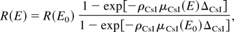
efficiency of 0.4 at 60 keV. The X-ray CCD was calibrated using a 59.5
keV Am241 radioisotope source. The source itself is
calibrated using a single-photon counting Ge(Li) detector with a
quantum efficiency for the energies of interest that is close to 100%.
The measurement results indicate 0.12 counts/keV at 59.5 keV; from
that calibration point, the response of the X-ray CCD can be
extrapolated using the X-ray absorption in CsI from the NIST
database:
where ΔCsI = 140 μm is the scintillator thickness,
E0 = 59.5 keV is the calibration energy,
ρCsI = 4.51 g/cm3 is the density of CsI,
and the data for the mass attenuation coefficient, μ(E),
measured in square centimeters per gram can be found at
http://physics.nist.gov/PhysRefData/FFast/html/form.html.
In addition to the response of the CsI(Tl) scintillator, the
transmission of the X-ray through a ΔBK7 = 12.7-mm-thick
BK7 mirror tilted at 40° must be taken into account: As seen in
Figure 8, the X rays produced at the
interaction point propagate through this final folding mirror before
detection. BK7 is a Crown glass containing 67% SiO2, 12.6%
B2O3, 8.1% Na2O, and 12.3%
K2O; the percentages are given in terms of weight, and the
X-ray mass attenuation coefficients add up linearly, provided the
relative compositional weight fractions and atomic weights are properly
taken into account; the mass density of BK7 is 2.51
g/cm3. Finally, the multilayer dielectric coating used
to reflect the focusing IR beam is extremely thin, and does not
significantly absorb the X rays.
Although the number of photons produced in a single shot is
sufficient to be detected by the X-ray CCD, better statistics are
obtained for integration times of 10 s, representing 100 shots. It is
found that the pointing stability of the X-ray beam is very good,
because no significant broadening of the angular X-ray distribution can
be detected over long integration times.
Figure 12 shows a typical X-ray image
captured by the CCD. The effect of the horizontal and vertical electron
beam emittance is striking: For a cylindrical spot, the electron beam
diverges faster in the vertical direction, and the X rays, which are
primarily scattered along the individual velocities of the electrons
due to the Doppler effect, clearly reflect the electron beam transverse
phase space.
Top: False color image of the X-ray angular energy distribution
captured by the CCD over 10 s of integration. Bottom: Lorentzian
distribution (1 +
γ2θ2)−1 along the
direction of polarization, for γ = 107 (red); experimental data
(blue dots); and theoretically calculated pattern after transmission
through the BK7 mirror, taking into account the energy-dependent
response of the CCD (green).
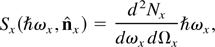
A closer examination and analysis of the angular distribution of
X-ray energy captured by the CCD provides valuable information on the
X-ray phase space, and is outlined in the following paragraphs. The
X-ray source can be characterized by the number of photons scattered
per unit frequency and solid angle in a single shot,
d2Nx
/dωx
dΩx, which is a quantity that can be
determined theoretically using either of the two codes mentioned in
Section 2. The spectral energy density radiated is simply given by
where
is the direction of observation. To obtain a relation between the
X-ray CCD signal and the spectral energy density at the source,
propagation through various materials must be taken into account,
as well as the response of the CCD. Taking into account the BK7
mirror and a ΔAl = 1-mm Al window, we first obtain
the transmitted spectral density,
The CCD yields an energy-integrated response, which can be calculated
by taking the integral of the product of the transmitted spectral
density and the CsI response over all frequencies and dividing by the
number of shots:
on a given X-ray CCD pixel, this translates into a signal
Here, we have used the pixel size and the distance from the source,
L, which is equal to 1.5 m, in the specific case of Figure 12, and the fact that for small angles sin
θ ≃ θ and cos θ ≃ 1 −
(θ2/2) ≃ 1. The indices i and
j refer to the pixel position, with i = j =
0 on-axis. Integration over all solid angles, or summation over all
pixels, yields the X-ray dose, which is approximately 3 ×
106. For typical X-ray runs, the maximum dose per shot is
approximately 20% larger than the average dose per shot, showing good
overall system stability.
Additional information is contained in the pixel signal distribution,
and can be understood by considering Figure
13: Here, we have plotted the spectrum at various angles ranging
from 0 to 12 mrad, both along the laser polarization (top), and across
it (center). It is clear that the radiation pattern is asymmetric, as
well as the spectral content; this is due to both the asymmetric
emittance and to the polarization. Along the laser polarization, the
spectrum downshifts rapidly with angle, leading to a very strong
attenuation in the BK7 mirror and a narrow radiation pattern, as
illustrated in Figure 12 (bottom), which
shows superb agreement between the theoretical angular energy
distribution, taking into account the BK7, and the measured data. Note
that the red curve, which shows the Lorentzian energy distribution
1/(1 + γ2θ2), is much wider than the
recorded data; this is because the emittance, polarization, and
transmission effects are not taken into account by this simple model.
Returning to our discussion, we see that across the laser polarization,
the downshift is much slower because of the high-energy contribution of
electrons with a high angle of incidence due to the emittance, as shown
schematically in Figure 13 (bottom); this
leads to better transmission through the BK7, and to a highly
asymmetric pattern on the CCD.
Top: Energy spectra at 4 different values of
θx; 0 mrad (dark blue), 4 mrad (red), 8 mrad
(green), 12 mrad (aqua). Center: Energy spectra at 4 different values
of θy; 0 mrad (dark blue), 4 mrad (red), 8
mrad (green), 12 mrad (aqua). The electron beam parameters correspond
to the experimental conditions in Figure 12.
Bottom: Illustration of the spectral and angular broadening effects
induced by the electron beam emittance.
4.2. X-ray dose as a function of delay
The timing between the laser pulse and the electron bunch can be
varied by using an optical delay line, and allows for measuring the
scattered X-ray dose as a function of the synchronization between the
two beams. Theoretically, the dominant effect for the 180°
interaction geometry and the PLEIADES parameters, where the inverse
beta function of the electron beam optics is much longer than the
diffraction length of the laser and where the electron bunch duration
is much longer than the laser pulse, is the Rayleigh range determined
by the laser focusing optics and beam quality. For the specific
measurements presented in Figure 14,
M2 ≃ 1.45, w0 ≃ 37
μm, and the central laser wavelength is λ0 = 815 nm,
the dose is expected to vary as a Lorentzian
with a HWHM equal to
πw02/cλ0
M2 ≃ 12.1 ps, which is superimposed to the
experimental data on Figure 14; the agreement
is quite good. The asymmetry probably results from the fact that the
electron bunch carries more charge near its front end: When the
collision occurs on the “upstream” side of the focus (right
side in Fig. 14), the high-charge front of
the bunch experiences a higher photon density than its low-charge tail;
this situation is reversed for collisions occurring on the other side
of the focus, which results in the observed difference in the number of
scattered photons.
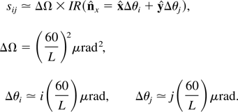
Experimentally measured variation of the X-ray dose with the delay,
Δt (red), and theoretically derived Lorentzian, [1 +
(Δt/τ)2]−1, where
τ =
πw02/cλ0
M2 = 12.1 ps.
4.3. On-axis X-ray spectrum
A number of different methods are available to determine the spectral
content of the scattered X rays. In general, three distinct categories
of diagnostics can yield spectral information: First and foremost,
diffraction crystals can be used to match the well-known Bragg
condition, 2d sin θB =
λB, where the so-called 2d-spacing of
the lattice is typically equal to a few angstroms; second, energy
detectors, such as scintillators and X-ray diodes, can be operated in
the single-photon counting regime, where a statistical analysis of the
data can yield the X-ray spectrum; finally, the fact that X-ray
attenuation in materials is generally a strong function of the photon
energy can be used to infer the spectrum of a source. The results
presented in this article were collected using the latter technique
because, in its present configuration and for the diagnostics currently
available, the two other approaches proved impractical: Because the X
rays propagate through a relatively thick BK7 mirror, the signal is
strongly attenuated for energies below 40 keV, and readily available
crystals, such as Si (111) with a 2d-spacing of 6.2712
Å, would yield very small Bragg angles or poor reflectivity. LiF
(420) crystals, with 2d-spacing of 1.801 Å, will be used
in the near future to confirm the spectral measurements. On the other
hand, in the present 180° degree geometry, the X-ray detectors are
placed directly in the line of sight of the bremsstrahlung produced by
the dark current in the linear accelerator, which results in background
levels that are incompatible with the aforementioned single-photon
counting technique. This problem will be mitigated by additional
shielding, limiting the rf pulse duration in the linac, using two
dipoles to offset the interaction region from the main linac axis, and
by diffracting the X-ray signal away from the components producing
background via bremsstrahlung and inner shell-edge fluorescence. In
view of the above, the most robust technique was chosen to perform the
initial spectral measurements: A series of 787-μm-thick Al plates
was placed in front of the X-ray CCD, obscuring only half of the
scintillator to normalize the transmission through a variable number of
plates. The technique is illustrated in Figures 15 and 16, where 15
plates were used for an integration time of 10 s; a lineout then
provides the value of the transmission for the on-axis spectrum.
Repeating this measurement technique then yields the transmission as a
function of the Al thickness.
Top: Illustration of the experimental procedure to measure the
attenuation through calibrated foils. Bottom: Linear X-ray attenuation
coefficient for Al, derived from the website at
http://physics.nist.gov/PhysRefData/FFast/html/form.html.
Top: CCD image obtained experimentally for 15 Al foils, each 787
μm thick. Bottom: Lineout along the box shown in the top figure,
and determination of the energy-integrated transmission, in this case,
approximately 0.40.
Spectral information can then be retrieved by applying the analysis
technique outlined in the following paragraphs. The transmission is
given by
where
Sx(ħωx,θ)
is the unknown spectral energy density and n is the number of
foils, of individual thickness δ = 787 μm. Both the density of
Al and its mass attenuation coefficient are well known:
ρAl = 2.70 g/cm3, and
μAl(ħωx) is shown in
Figure 15. We also note that for a small
solid angle on-axis, cos θ ≃ 1 −
(θ2/2), and can be set equal to one in Eq. (62). To
determine Sx, we introduce a trial
function, consisting of a series of m steps:
where H is the unit Heaviside step-function. With this, Eq. (62) can
be readily integrated, to obtain
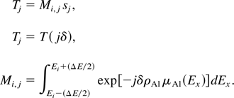
which can be recast as a linear system of equations, where
In Eq. (65), the coefficients Tj are
determined experimentally, whereas the matrix elements are derived from
the well-known X-ray transmission properties of Al; the unknowns are
the coefficients sj. Provided that the
number of measurements, n, is equal to the number of energy
bins, m, the system can be resolved, with the obvious caveat
that the energy sampling range must reasonably map the sought-after
spectrum. In practice, 9 × 9 systems were solved for, and it was
found that only a limited set of energy binnings provided
mathematically acceptable results, namely, that all the
sj coefficients be positive; moreover, all
such solutions yielded spectra with very similar energy dependence. The
result is shown in Figure 17, where it is
compared with the theoretical prediction; the spectrum inferred from
the transmission curve shown in Figure 16 is
consistent with the theory. Note that as the measurements are performed
with the X-ray CCD, the theoretical curve includes the transmission
through BK7 and the response of the CsI scintillator.
Top: Energy-integrated transmission as a function of the number of Al
foils; the experimental data is shown as dots with error bars; the blue
horizontal lines are theoretically predicted using the frequency-domain
three-dimensional code. Bottom: Theoretical spectral energy density at
the CCD (red), and spectrum inferred from the transmission measurements
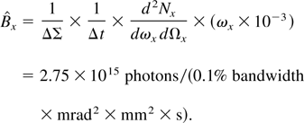
(blue; see text). The corresponding peak brightness is
= 2.75 × 10¹⁵ photons/(0.1% bandwidth ×
mrad2 × mm2 × s).
4.4. Peak on-axis X-ray brightness
Starting from the good inferred agreement between the
three-dimensional codes and the spectral measurements, the peak
brightness of the source can be evaluated as follows: The output of the
three-dimensional frequency-domain code mentioned in Section 2
describes the time-integrated photon spectral density per unit
frequency per unit solid angle,
d2Nx
/dωx
dΩx; multiplying this quantity by the
photon energy, ħωx, then yields the
energy spectral density radiated at the source,
Sx =
d2Wx
/dωx
dΩx. The next step consists of taking
into account the transmission through the ½-in. BK7 mirror and
the 1-mm Al window, by multiplying Sx by
TBK7(ħωx)TAl(ħωx),
as expressed in Eq. (58). Considering a small solid angle on-axis,
ΔΩ, the total energy deposited on the corresponding area of
the X-ray CCD, and properly taking into account the energy response of
the CCD, as described in Eq. (56), we find that
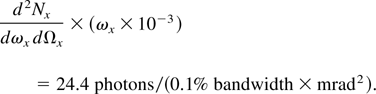
We now consider the experimental measurement of the energy deposited
on-axis in a single X-ray shot: A 6 × 6 pixels area registers 480
counts; as the detector is positioned 1.905 m away from the source, the
corresponding solid angle is ΔΩ = (6 × 60 ×
10−6/1.905)2 = 0.036 mrad2.
Comparing the energy density in Eq. (66) and the experimental count
density, the spectrum can be used to calculate the integrated energy
response on the CCD, as specified in Eq. (59); for the spectrum
inferred in the previous section, this parameter is equal to 0.122
count/keV. The energy deposited is 3.94 MeV, and the integrated
energy density on-axis is dWx
/dΩx = 9.69 ×
104 keV/mrad2. The number of photons per 0.1%
bandwidth, per unit solid angle can now be determined by properly
scaling the three-dimensional code output to match the experimental
energy density: On-axis, we have
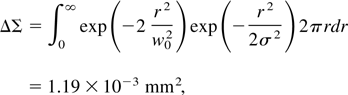
At this point, we need to evaluate the source size and the X-ray
pulse duration to obtain the peak brightness on-axis. To first order,
the source size is simply given by the overlap integral of the electron
and photon density distributions at the focus,
for w0 = 32 μm and σ = 27 μm rms;
similarly, the temporal duration of the X-ray pulse is given by that of
the electron bunch, and we have
as σt = 3 ps rms. Finally, the on-axis peak
brightness is
This value is in good agreement with the theoretical value calculated
by the three-dimensional codes.
4.5. K-edge radiography in tantalum
The final set of experimental data discussed in this article
demonstrates the γ2-tunability of the Compton scattering
source, as well as its capability to perform radiography in
high-Z materials, and to use the correlation between the
scattering angle and the photon energy, shown in Figure 4, to detect the K-edge of Ta. The
basic setup consists of propagating the X-ray beam through a thin foil
of high-Z material, with a K-edge located near the
peak of the on-axis spectrum. In the case of a 0.005-in.-thick Ta foil,
where the K-edge lies at 67.46 keV, the results are shown in
Figure 18. When the electron beam operates at
54.9 MeV, the peak of the on-axis spectrum is at 71.5 keV, just above
the K-edge of Ta. As a result strong absorption is observed
on-axis, whereas the lower energy X rays scattered off-axis are below
the edge and propagate with little attenuation. The elliptical shape of
the ring surrounding the on-axis hole is due to a combination of
emittance and polarization effects, and is well modeled by our
three-dimensional code, as shown in Figure
18. Operating the machine at 56.9 MeV pushes the peak of the
on-axis spectrum to 76.7 keV, which is sufficiently far above the
K-edge to recover some transmission: The hole fills up. Again,
this is in very good agreement with the pattern predicted
theoretically. Finally, a 3.6% variation in the electron beam energy
yields a 7% variation in the photon energy, a clear signature of the
quadratic scaling of the X-ray energy with γ.
Top left: Experimentally measured angular energy distribution after
propagation through a 0.005-in. Ta foil, for an electron beam energy of
54.9 MeV. Bottom left: Theoretically predicted CCD response under the
same conditions. Top right: Experimentally measured angular energy
distribution after propagation through a 0.005-in. Ta foil, for an
electron beam energy of 56.9 MeV. Bottom right: Theoretically predicted
CCD response under identical conditions.