


Introduction
The four-port rat-race (or ring hybrid which is a form of 180° coupler) and 180° hybrid couplers provide the sum and difference in operations of two input signals at two isolated ports. In other words, they create 180° relative phase difference between the signals at the output ports for a signal arriving at one input port and 0° relative phase difference for a signal arriving at the other input port. This relative phase difference between the output signals is 90° for the 90° quadrature hybrid coupler. But, with the 180° hybrid coupler, if two distinct signals are incident at two input ports, two equally divided portions of each input signal appear at the two output ports. One pair of output signals, each including two portions from the two input signals, is out of phase while the two other output signals are in phase. The principle and the S-matrix of the conventional 180° hybrid coupler (rat-race) are described in [Reference Pozar1]. This hybrid coupler with its specific phasing network between all ports has found application in many types of RF and microwave signal routing-based integrated circuits such as balanced mixers [Reference Maas2], multiport interferometers [Reference Moghaddasi and Wu3], and in-phase/quadrature mixers [Reference Napijalo and Kearns4].
The 180° hybrid couplers have been investigated for different aspects including bandwidth enhancement using coupled lines [Reference March5], broadband phase inverter [Reference Rehnmark6–Reference Mo, Xue and Chan11], size reduction using shunt open stubs [Reference Chuang12, Reference Eccleston and Ong13], spurious suppression [Reference Kuo, Wu and Chiou14], and arbitrary power division [Reference Cheng and Yeung15, Reference Cheng and Chick16].
One of the main drawbacks of the conventional topology of the ring-shaped rat-race coupler is related to the respective position of input–output ports, which makes laying out complicated when applied to the interconnects, integration, and packaging of microwave circuits. This demands for multilayer circuits or utilization of crossovers and/or vias, which may unfortunately bring up other limitations especially in high-frequency circuits. Therefore, this aspect has recently come into light and novel topologies of 180° hybrid couplers with non-interspersed ports have been developed, which are configured through cascading couplers and phase shifters, in essence.
Such different topologies of 180° hybrid coupler were first introduced by [Reference Ang, Leong and Lee17] in which non-interspersed ports were obtained by two-section hybrids using cascaded hybrid rings. Another configuration of a pair of cascaded microstrip coupled line couplers and one 180° phase shifter was reported by [Reference Park and Byungje18]. This topology that still suffers from the location of input–output ports is shown in Fig. 1(a) for reference. Based on this topology, multilayer hybrid couplers were developed and implemented using the multilayer low-temperature co-fired ceramic (LTCC) technology [Reference Napijalo and Kearns4]. Within multilayer implementation of the topology in Fig. 1(a), a pair of input and output was implemented in one layer and the other pair in the other layer. To position the pair of inputs in one layer and the pair of outputs in another layer, the interconnections between three sections were rewired in an improved topology as it is shown in Fig. 1(b). However, such topology has limited applications and may not be used within single-layer circuits.
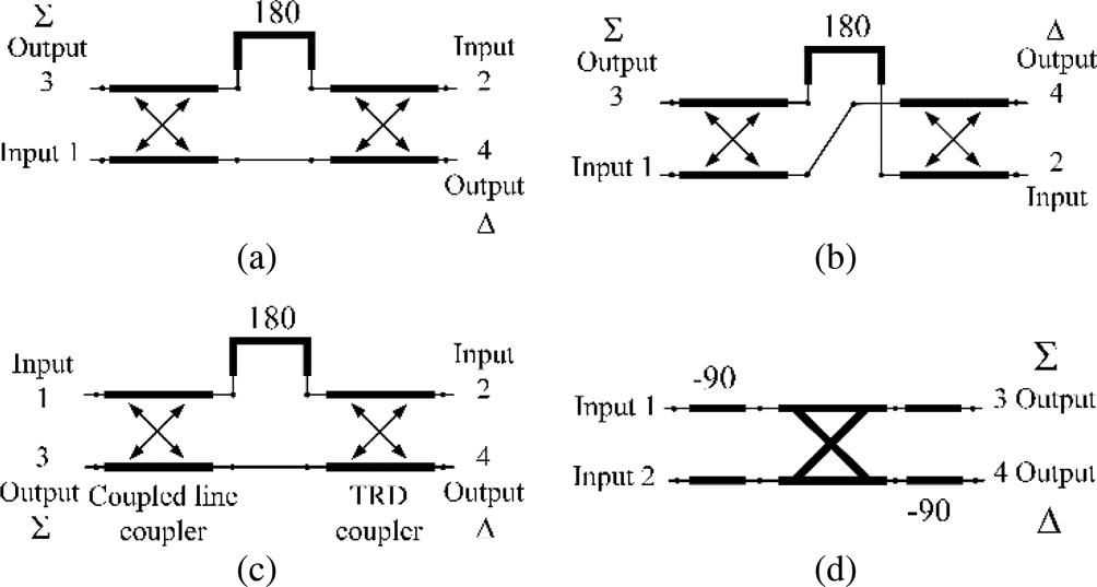
Fig. 1. The 180° hybrid couplers with typical topologies and input/output ports. (a) [Reference Park and Byungje18], (b) [Reference Napijalo and Kearns4], (c) [Reference Liu, Fang, Wang and Fu20], (d) This paper.
A near-TEM Lange hybrid was also reported in [Reference Napijalo19]. However, the use of vias for interlayer connection or bond-wires limits the frequency of operation and increases the gain and phase imbalances due to the parasitic inductance in vias. Another topology comprising of a weak-coupling parallel coupled line and a strong-coupling trans-directional (TRD) coupler connected with a 180° phase shifter was proposed by [Reference Liu, Fang, Wang and Fu20]. This topology is depicted in Fig. 1(c). The use of periodic shunt capacitor components in TRD relaxes the necessity of tightly coupled lines and allows for the use of a single-layer printed circuit board (PCB) technique without any vias or bond wires. However, the capacitors may fail to operate at very high frequencies and increase the cost.
In this paper, an alternative topology of rat-race with non-interspersed ports is proposed, which is sketched in Fig. 1(d). The proposed topology can be categorized in the same family of newly introduced hybrid couplers that are essentially built up through cascading couplers and phase shifters. The proposed hybrid topology does not require any vias, bond-wires, or lumped components and facilitates implementation on a single layer of substrate for interconnection, integration, and packaging purposes, especially for high-frequency circuits.
The principles of this topology are discussed along with analytical solutions in the next sections. The proposed coupler is also implemented in this work using our in-house technology of Miniaturized Hybrid Microwave Integrated Circuit (MHMIC) to demonstrate its performances around 77 GHz. Measurement results of the prototyped 180° hybrid coupler are presented.
Principles of the proposed topology of 180° hybrid coupler
As it is shown in Fig. 1(d), the proposed topology of 180° hybrid coupler is comprised of one quadrature coupler and two 90° phase shifters. With this configuration, two input ports can be located on one side and outputs on the other side. As opposed to the previously reported structures, which were mainly based on backward-coupled line couplers, the quadrature coupler in the proposed topology is a forward coupler. This configuration can be implemented with both TEM- or quasi-TEM mode structures, such as microstrip, and non-TEM structures, such as substrate-integrated waveguide. In this work, TEM-mode-based structures are selected to realize the proposed 180° coupler topology at millimeter-wave frequencies. Figure 2 shows the TEM-mode-based topology of the 180° hybrid coupler, which consists of wideband Schiffman phase shifters [Reference Schiffman21–Reference Zhang, Liu, Wu, Wang, Su and Gao28] and a quadrature branch-line coupler [Reference Pozar1].
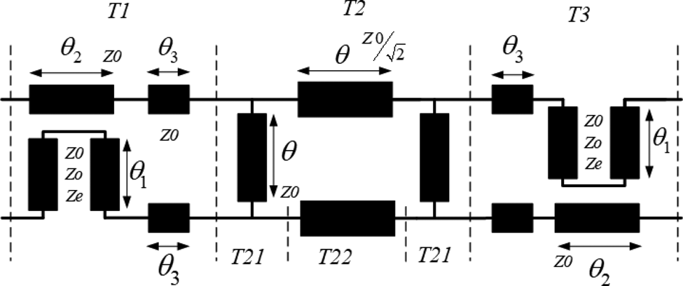
Fig. 2. Implementation of the proposed topology in TEM-mode structures.
Theoretical analysis
To theoretically analyze the proposed 180° hybrid coupler, transfer T-matrix is derived that relates the output port power wave variables to the input port power wave variables of a network [Reference Dobrowolski29]. It should be highlighted that the standard definition of T-matrix of the four-port network is defined in accordance with [Reference Frei, Cai and Muller30, eq. 8] herein, and the ports reference impedances in our analysis are identical. In view of the above, the structure shown in Fig. 2 is first divided into three distinct segments, then the overall T-matrix is derived from the multiplication of three matrices, i.e. T1 × T2 × T3. The T-matrix of each can be derived as it is briefly explained next.
T-matrix of the first segment (T1)
First segment consists of a Schiffman phase shifter and a transmission line with an electrical length of θ 3. T-matrix of the Schiffman phase shifter can be obtained by converting the ABCD parameters of coupled-line with connected end-ports that were reported by [Reference Geogre, Zysman and Johnson31] into T-parameters using the equations from [Reference Frickey32, Reference Marks, Williams and Frickey33].
The matrix T1 can be expressed as in (1) where Z e and Z o denote the even and odd mode impedances of the coupled-line in the phase shifter part and Z 0 is the characteristic impedance of the transmission line.
 $$T1 = \left[ \matrix{\matrix{ {T1sh_{11}} & {{\rm} 0} & \qquad\quad{{\rm} 0} & \qquad\quad{{\rm} 0} \cr} \hfill \cr \matrix{ 0 & \qquad\quad{{\rm} T1sh_{22}} & {{\rm} 0} & \qquad\quad{{\rm} T1sh_{24}} \cr} \hfill \cr \matrix{ 0 & \qquad\quad{{\rm} 0} & \qquad\quad {{\rm} T1sh_{33}} & {{\rm} 0} \cr} \hfill \cr \matrix{ 0 & \qquad\quad{{\rm} T1sh_{42}} & {{\rm} 0} & \qquad\quad{{\rm} T1sh_{44}} \cr} \hfill} \right]$$
 $$\eqalign{T1sh_{11} = &\lpar {\cos (\theta_3)-j\sin (\theta_3)} \rpar \lpar {\cos (\theta_2)-j\sin (\theta_2)} \rpar \cr T1sh_{22} = &\displaystyle{{\lpar {\cos (\theta_3)-jsin(\theta_3)} \rpar \lpar {Z_0Z_e\cot (\theta_c)-j\lpar {Z_0^2 + Z_eZ_o-jZ_0Z_otan(\theta_c)} \rpar } \rpar } \over {Z_0\lpar {Z_ecot(\theta_1) + Z_otan(\theta_c)} \rpar }} \cr T1sh_{24} = &\displaystyle{{\lpar {Z_0^2 -Z_eZ_o} \rpar \lpar {-j\cos (\theta_3) + \sin (\theta_3)} \rpar } \over {Z_0\lpar {Z_ecot(\theta_1) + Z_otan(\theta_1)} \rpar }} \cr T1sh_{33} = &\lpar {\cos (\theta_3) + j\sin (\theta_3)} \rpar \lpar {\cos (\theta_2) + j\sin (\theta_2)} \rpar \cr T1sh_{42} = &\displaystyle{{(Z_0^2 -Z_eZ_o)\lpar {\,j\cos (\theta_3) + \sin (\theta_3)} \rpar } \over {Z_0\lpar {Z_ecot(\theta_c) + Z_otan(\theta_1)} \rpar }} \cr T1sh_{44} = & \displaystyle{{\lpar {\cos (\theta_3) + jsin(\theta_3)} \rpar \lpar {Z_0Z_e\cot (\theta_1) + j\lpar {Z_0^2 + Z_eZ_o + jZ_0Z_otan(\theta_1)} \rpar } \rpar } \over {Z_0\lpar {Z_ecot(\theta_1) + Z_otan(\theta_1)} \rpar }}.} $$
T-matrix of second segment (T2)
The matrix T2 can be obtained through multiplying the submatrices of T21 × T22 × T21. T22 pertains to the T-matrix of a pair of transmission lines with a characteristic impedance of  $Z0/\sqrt 2 $ and identical electrical lengths θ while T21 denotes the T-matrix of one branch of a branch line directional coupler with characteristic impedance of Z 0 and electrical length θ that can be found in [Reference Dobrowolski29]. Hence, the matrix T2 can be expressed by
 $$T2 = \left[ {\matrix{ {Th_{11}} & {Th_{12}} & {Th_{13}} & {Th_{14}} \cr {Th_{12}} & {Th_{11}} & {Th_{14}} & {Th_{13}} \cr {-Th_{13}} & {-Th_{14}} & {Th_{33}} & {Th_{34}} \cr {-Th_{14}} & {-Th_{13}} & {Th_{34}} & {Th_{33}} \cr}} \right]$$
 $$\eqalign{Th_{11} = &\cos (\theta )\lpar {1-j\cot (-\theta )} \rpar +{\rm} \displaystyle{{\sin (\theta )\lpar {{\sin}^2(-\theta )\lpar {0.5j{\cot}^2(-\theta )-\cot (-\theta )-1.5j} \rpar + 0.5j} \rpar } \over {\sqrt 2 {\sin} ^2(-\theta )}} \cr Th_{12} = &\displaystyle{{\sin (\theta )\lpar {1-j\cot (-\theta )} \rpar + j\cos (\theta )\sqrt 2} \over {\sqrt 2 \sin (-\theta )}} \cr Th_{13} = &-j\cot (-\theta )\cos (\theta )+ \displaystyle{{\sin (\theta )\lpar {{\sin}^2(-\theta )\lpar {0.5j{\cot}^2(-\theta )-0.5j} \rpar + 0.5j} \rpar } \over {\sqrt 2 {\sin} ^2(-\theta )}} \cr Th_{14} = &\displaystyle{{-j\cot (-\theta )\sin (\theta ) + j\cos (\theta )\sqrt 2} \over {\sqrt 2 \sin (-\theta )}}} $$
 $$\eqalign{Th_{33} = &\cos (\theta )\lpar {1 + j\cot (-\theta )} \rpar + {\rm} \displaystyle{{\sin (\theta )\lpar {{\sin}^2(-\theta )\lpar {-0.5j{\cot}^2(-\theta )-\cot (-\theta ) + 1.5j} \rpar -0.5j} \rpar } \over {\sqrt 2 {\sin} ^2(-\theta )}} \cr Th_{34} = &\displaystyle{{\sin (\theta )\lpar {1 + j\cot (-\theta )} \rpar -j\cos (\theta )\sqrt 2} \over {\sqrt 2 \sin (-\theta )}}.} $$
T-matrix of third segment (T3)
The matrix T3 pertains to another phase shifter which is connected at the output port of the branch-line hybrid coupler via a transmission line with a length of θ 3. The matrix T3 can be expressed as:
 $$T3 = \left[ \matrix{\matrix{ {T3sh_{11}} & {{\rm} 0} & \qquad \quad{{\rm} T3sh_{13}} & {{\rm} 0} \cr} \hfill \cr \matrix{ 0 & \qquad \quad {{\rm} T3sh_{22}} & {{\rm} 0} & \qquad\;\, {{\rm} 0} \cr} \hfill \cr \matrix{ {T3sh_{31}} & {{\rm} 0} & \qquad \quad{{\rm} T3sh_{33}} & {{\rm} 0} \cr} \hfill \cr \matrix{ 0 & \qquad \;\, {{\rm} 0} & \qquad \quad{{\rm} 0} & \qquad \quad{{\rm} T3sh_{44}} \cr} \hfill} \right]$$
 $$\eqalign{T3sh_{11} = &\displaystyle{{\lpar {\cos (\theta_3)-jsin(\theta_3)} \rpar \lpar {Z_0Z_e\cot (\theta_1)-j\lpar {Z_0^2 + Z_eZ_o-jZ_0Z_otan(\theta_1)} \rpar } \rpar } \over {Z_0\lpar {Z_ecot(\theta_1) + Z_otan(\theta_1)} \rpar }} \cr T3sh_{22} = &\lpar {\cos (\theta_3)-j\sin (\theta_3)} \rpar \lpar {\cos (\theta_2)-j\sin (\theta_2)} \rpar \cr T3sh_{13} = &-\displaystyle{{\,j\lpar {Z_0^2 -Z_eZ_o} \rpar \lpar {\cos (\theta_3)-jsin(\theta_3)} \rpar } \over {Z_0\lpar {Z_ecot(\theta_1) + Z_otan(\theta_1)} \rpar }} \cr T3sh_{31} = &\displaystyle{{\,j\lpar {Z_0^2 -Z_eZ_o} \rpar \lpar {\cos (\theta_3) + jsin(\theta_3)} \rpar } \over {Z_0\lpar {Z_ecot(\theta_1) + Z_otan(\theta_1)} \rpar }} \cr T3sh_{33} = &\displaystyle{{\lpar {\cos (\theta_3) + jsin(\theta_3)} \rpar \lpar {Z_0Z_e\cot (\theta_1) + j(Z_0^2 + Z_eZ_o + jZ_0Z_otan(\theta_1))} \rpar } \over {Z_0\lpar {Z_ecot(\theta_1) + Z_otan(\theta_1)} \rpar }} \cr T3sh_{44} = &\lpar {\cos (\theta_3) + j\sin (\theta_3)} \rpar \lpar {\cos (\theta_2) + j\sin (\theta_2)} \rpar .} $$
All derived analytical T parameters are verified through comparison with the simulated ones in ADS for validation purposes.
Finally, the overall T-matrix of the proposed 180° hybrid coupler can be formulated by multiplying three matrices via arithmetic tools such as Mathematica. Due to the complexity of the resulting equations, they are not brought in here. However, the derived T-matrix would be helpful for computer-aided design when the conditions of 90° phase shifters and branch-line couplers are applied.
The phase difference between signals at the output ports of the Schiffman phase shifter was formulated in [Reference Schiffman21], which reads as
 $$\Delta \varphi = K\theta _1-\cos ^{-1}\left( {\displaystyle{{R-\tan {(\theta_1)}^2} \over {R + \tan {(\theta_1)}^2}}} \right),$$
where K = θ 2/θ 1 and R = Z e/Z o. For 90° phase shifter, K and θ 1 are selected to be 3 and π/2 at the center frequency, respectively. At the center frequency, where θ and θ 1 are π/2 and θ 2 is 3π/2, the T-matrix of the proposed 180° hybrid coupler would be
 $$T = \displaystyle{1 \over {\sqrt 2}} \left[ {\matrix{ {\matrix{ {-e^{-2j\theta_3}} \cr {-e^{-2j\theta_3}} \cr 0 \cr 0 \cr}} & {\matrix{ {e^{-2j\theta_3}} \cr {-e^{-2j\theta_3}} \cr 0 \cr 0 \cr}} & {\matrix{ 0 \cr 0 \cr {-e^{2j\theta_3}} \cr {-e^{2j\theta_3}} \cr}} & {\matrix{ 0 \cr 0 \cr {e^{2j\theta_3}} \cr {-e^{2j\theta_3}} \cr}} \cr}} \right]$$
Substituting the T-matrix elements into the T-to-S parameter conversion equations in [Reference Frei, Cai and Muller30], one can yield
 $$[S] = \displaystyle{{-e^{-2j\theta _3}} \over {\sqrt 2}} \left[ {\matrix{ {\matrix{ 0 \cr 0 \cr 1 \cr {-1} \cr}} & {\matrix{ 0 \cr 0 \cr 1 \cr 1 \cr}} & {\matrix{ 1 \cr 1 \cr 0 \cr 0 \cr}} & {\matrix{ {-1} \cr 1 \cr 0 \cr 0 \cr}} \cr}} \right],$$
which confirms the hybrid is matched at input ports 1 and 2. Moreover, (6) shows that at output port 4, there is a 180° phase difference between the input signals from ports 1 and 2, whereas this phase difference is zero at output port 3. The S-matrix in (6) is almost the same as that of the classic ring hybrid. The only difference is that the signals at the output ports are either in-phase or out-of-phase with respect to the input signals, whereas the output signals in the classic ring hybrid are in quadrature phase with the input signal [Reference Pozar1].
To examine the phase difference characteristic of the proposed 180° hybrid at frequencies other than the center frequency, the derived overall T-matrix of the proposed hybrid is converted to S-matrix through conversion equations from [Reference Frei, Cai and Muller30] via arithmetic tools such as Mathematica. It should be noted that at frequencies other than the center frequency, the condition of θ 1 = θ and θ 2 = 3θ remains valid. In addition, the coupled line is matched when  $Z_0 = \sqrt {Z_oZ_e} $ [Reference Schiffman21]. Under these conditions, the phase difference at output ports 3 and 4 can be formulated from the S-matrix of the proposed hybrid as in the following:
 $$\eqalign{\Delta = &\angle S_{13}-\angle S_{14} \cr \angle S_{13} = &\angle \left[ {\displaystyle{{\lpar {-0.54582 + j1.31773\cot (\theta )} \rpar \csc {{\rm (}\theta )}^2} \over {\lpar {\Phi_1 + \Phi_2 + \Phi_3} \rpar {\lpar {\cos (3\theta ) + j\sin (3\theta )} \rpar }^2}}} \right] \cr \Phi _1 = &\,0.614047 + j2.52241\cot (\theta )^3 + \cot (\theta )^4-0.136455\csc {\rm (}\theta )^2 \cr \Phi _2 = &\,0.0682275\csc (\theta )^4 + \cot (\theta )^2(-3.15786-1.06823\csc (\theta )^2) \cr \Phi _3 = &\cot (\theta )(-j1.97659-j0.658863\csc (\theta )^2),} $$
 $$\eqalign{\angle S_{14} = &\angle \left[ {\displaystyle{{\,jZ0\lpar {1 + R\cot {(\theta )}^2} \rpar csc(\theta )\lpar {\Psi_1} \rpar } \over {\lpar {\Psi_2} \rpar \lpar {\Psi_3 + \Psi_4 + \Psi_5} \rpar \lpar {\cos (3\theta ) + j\sin (3\theta )} \rpar }}} \right] \cr \Psi _1 = &-0.783612 + j1.2612\cot (\theta ) + \cot (\theta )^2 + 0.261204\csc (\theta )^2 \cr \Psi _2 = &-Z0 + j2Z_e\cot (\theta ) + RZ0\cot (\theta )^2 \cr \Psi _3 = &0.614047 + j2.52241\cot (\theta )^3 + \cot (\theta )^4-0.136455\csc (\theta )^2 \cr \Psi _4 = &0.0682275\csc (\theta )^4 + \cot (\theta )^2\lpar {-3.15786-1.06823\csc {(\theta )}^2} \rpar \cr \Psi _5 = &\cot (\theta )\lpar {-j1.97659-j0.658863\csc {(\theta )}^2} \rpar .} $$
One can observe in (7) that the bandwidth of the 180° phase difference depends on the ratio of even to odd mode impedances, i.e. R = Z e/Z o. In Fig. 3(a), simulation results of the proposed hybrid with ideal components through the commercial package of ADS is compared with the analytical equations concluded in (7). The excellent agreement between simulation and analytical results for two different values of R validates the theoretical analysis throughout this paper.

Fig. 3. Changes in phase difference and bandwidth for two different values of R. (a) Phase difference control and comparison between results of simulation and analytical equations. (b) Bandwidth control over R for (δ) of ± 2° and ± 5°, obtained from analytical analysis in (7).
The bandwidth in which the desired maximum deviation takes place can be determined by controlling R. Figure 3(b) shows the change of bandwidth versus different values of R, which is helpful in the design of the proposed coupler. It should be noted that abrupt changes in BW that can be observed in Fig. 3(b) are because the phase difference curves at maximum and minimum points exit the defined range of phase difference values, i.e. ±5° or ±2°.
Design of the proposed coupler
The proposed coupler has fairly a simple design procedure. To design the proposed coupler, the even and odd mode impedances of the coupled line should be determined per the desired bandwidth of the maximum tolerable deviation from the 180° phase difference. Figure 3 can be used to find a suitable ratio of even to odd mode impedances to achieve the desired bandwidth. On the other hand, a matching condition to the reference impedance (i.e.  $Z_0 = \sqrt {Z_oZ_e} $) provides the second equation to determine the even and odd mode impedances and accordingly the coupling factor (C) of the coupled line (i.e. C = −20log[(R − 1)/(R + 1)]). The electrical lengths of θ 1and θ are 90° and θ 2 is 270°.
To discuss the characteristics of the proposed hybrid coupler, they are compared with other counterparts including classic rat-race and coupled-line from [Reference Park and Byungje18], based on simulations which are carried out using ideal blocks in ADS. Two different values of the ratio of even-to-odd mode impedances for each of the proposed hybrid (R) and the coupled-line hybrid (Zce/Zco)from [Reference Park and Byungje18] are considered for simulations and results are plotted in Fig. 4.

Fig. 4. Comparison of phase difference between our proposed 180° hybrid topology with the one proposed by Park in [Reference Park and Byungje18] and the classic rat-race. (a) Out-of-phase, (b) in-phase.
It can be observed in Figs 4(a) and 4(b) that the phase differences between output signals in the hybrid proposed by [Reference Park and Byungje18] are not affected by changes in the ratio of (Zce/Zco). Moreover, the bandwidth in which the maximum phase deviation of 5° occurs for both in-phase and out-of-phase components is slightly less than that of the rat-race hybrid coupler. However, the proposed hybrid has considerably larger bandwidth for both phase difference components with the same amount of deviation of 5°. This bandwidth can be controlled by changing R.
In Fig. 5(a), the hybrid couplers are compared in terms of matching at the input ports. One can see that the proposed hybrid has narrower bandwidth of VSWR with the value <1.22 (i.e. return loss >20 dB), while the hybrid coupler in [Reference Park and Byungje18] is completely matched given the condition Z02 = Zce × Zco is satisfied for any non-zero coupling factor, regardless of the length of the coupled lines. It should be pointed out the latter consequences can be concluded given the coupled line hybrid circuit of [Reference Park and Byungje18] is lossless.

Fig. 5. Comparison between our proposed 180° hybrid topology with the one proposed by Park in [Reference Park and Byungje18] and the classic rat-race. (a) VSWR, (b) amplitude imbalance.
Figure 5(b) demonstrates the performance of the hybrids in terms of amplitude imbalance for the output signals. The proposed hybrid coupler has less bandwidth of 0.5 dB amplitude imbalance when compared to the classic rat-race hybrid. This remains unaffected by changes in R, whereas the amplitude imbalance of the output signals in the hybrid coupler of [Reference Park and Byungje18] can be controlled by changing the ratio (Zce/Zco). This ratio in hybrid coupler of [Reference Park and Byungje18] can be set for a larger bandwidth of 0.5 dB amplitude imbalance than that of the classic rat-race hybrid.
These characteristics of studied hybrids are summarized in Table 1 in terms of fractional bandwidth for comparison purposes. One can observe that the examined hybrids may not satisfy all desired specifications with an identical percentage of bandwidth. For instance, the structure in [Reference Park and Byungje18] has acceptable phase differences in limited bandwidth of only around 11% even though excellent matching is readily achievable across the whole band. Our proposed hybrid can have wider bandwidth for phase differences, but in a narrower bandwidth, it satisfies the desired input matching specification. Obviously, the bandwidth in which all specifications are satisfied is dominated by the narrowest bandwidth, e.g. 11.16% for coupler in [Reference Park and Byungje18]. Interestingly enough, our proposed coupler shows to be capable of satisfying all specifications in a wider bandwidth, i.e. 20%, than other couplers if the input VSWR of 1.5:1 is considered to be sufficient.
Table 1. Comparison of the 180° hybrid couplers

a Z ce and Z co are the even and odd mode impedances of the coupled-line couplers in the hybrid topology of [Reference Park and Byungje18], and Z02 = Z ce × Z co.
b Under-coupled.
c Over-coupled.
It is also worth noticing that the only characteristic that is affected by the value of R is the phase difference at the output ports, whereas VSWR and gain balance remain unchanged with the changes in R. Furthermore, the changes in the bandwidth of phase differences are in the opposite direction. In other words, increasing R to larger values than 2.15 would increase the 180° phase difference, but reduces the bandwidth of 0° phase difference. Therefore, selecting the optimum value of R depends on the desired phase differences. Nevertheless, designer can conclude the approximate starting design value of R that can satisfy the desired bandwidth for either phase differences, using the information herein.
Prototyping and measurements
As it has already been mentioned, the proposed topology can outperform other existing counterparts as the design frequency increases, because no via, wire-bonding, or lumped elements are essentially used that can affect matching, phase, and amplitude imbalance. Therefore, the proposed hybrid was designed and implemented for operation around 77 GHz, using our in-house MHMIC fabrication process on an Alumina ceramic substrate with a permittivity of around 9.9 and a thickness of 0.254 mm. Through our in-lab MHMIC process, circuits with minimum microstrip linewidth of 20 µm can be prototyped. The prototyped MHMIC die is displayed in Fig. 6. Small modifications in the original configuration at the input of phase shifter are made within the optimization process in simulations.

Fig. 6. Prototyped hybrid on ceramic die; ports #1, #2, #3, #4 in layout correspond to ports #1, #3, #4, #2, respectively, in standard port definition from [Reference Frei, Cai and Muller30]. R1 = 393.7 µm, R2 = 172.7 µm, d = 624.8 µm, v1 = 162.6 µm, l1 = 1.46 mm, l2 = 94 µm, v2 = 647.7 µm, C1 = 142.24 µm, C2 = 114.3 µm, wc1 = 68.6 µm.
To measure the S-parameters through two-port VNA, a few circuits are fabricated on the same die. The microscopic view shows one of the circuits with details. The measuring ports are connected to the designed coplanar adaptor while the unused ports are loaded with integrated matched resistors and RF grounds. The quadrature round-shaped coupler with a branch-line impedance of 70.7 Ω was designed for this frequency of operation. To minimize the radiation loss of the microstrip transmission line, the reference characteristic impedance was selected to be 70.7 Ω.
To assess the performance of the prototyped hybrid, two-port on-wafer S-parameter measurement was carried out using the probe station (Karl Suss) with VNA (Agilent Technologies PNA-X, N5247A) shown in Fig. 7. To preserve the repeatability of amplitude and phase measurements, the Ground-Signal-Ground (GSG) probe (Picoprobe by GGB Industries-Model 120) with a pitch size of 150 µm was positioned on the same place over the coplanar adaptors with the same amount of pressure using high accuracy controllers. To de-embed the effect of transitions from the probe to the input ports of the designed hybrid, a standard Through-Reflect-Line (TRL) calibration kit was also designed on the same die for calibration purposes.

Fig. 7. Measurement setup which is held on mm-wave probing station.
The phase and amplitude measurement results, corresponding to the port definition in Fig. 6, are shown in Figs 8(a) and 8(b). It should be noted that, ports #1, #2, #3, #4 in layout correspond to ports #1, #3, #4, #2, respectively within the standard port definition in [Reference Frei, Cai and Muller30].

Fig. 8. Comparison of measured and simulated of S-parameters. (a) Amplitude, (b) phase differences:  $PH423 = \angmsd {\rm S}_{42}-\angmsd {\rm S}_{43}$,
  $PH123 = \angmsd S_{12}-\angmsd S_{13}$,
  $PH142 = \angmsd S_{12}-\angmsd S_{42}$,
  $PH143 = \angmsd S_{13}-\angmsd S_{43}$.
The designed 180° hybrid is very well matched (return loss >10 dB) over 10 GHz bandwidth. At the center frequency of 78 GHz, the measured values of isolation are about 30 dB and the port-to-port insertion loss varies between 0.6 and 1.25 dB for all measured pairs of ports. Gain imbalance at the same frequency was measured to be 0.3 dB and it varies within the range of −0.4 to 1.25 dB throughout the whole 10 GHz bandwidth. The measured phase difference shown in Fig. 8 agrees well with the simulation values.
The performance of the prototyped device is compared with the recently reported 180° hybrids in Table 2 based on the measurement results, although the operational frequency of them is quite different. One can observe that with the tight condition of 5° deviation from phase differences of the output signals, it covers a fractional bandwidth of around 5% which corresponds to roughly 4 GHz bandwidth around 77 GHz. This is sufficient for applications such as automotive radar (i.e. 76–77 GHz) or backhaul radios (71–76 GHz). In these frequency bands, the prototyped hybrid can be matched with return loss values larger than 15 dB and isolation of better than 20 dB.
Table 2. Comparison of measured performances of 180° hybrid couplers

a Only central frequency.
b Simulation results of the circuit in [Reference Napijalo19, Fig. 11].
Table 2 shows that the prototype of the proposed hybrid possesses the least measured fractional bandwidth in terms of matching, isolation, or phase differences, in comparison to other works. Nevertheless, it has sufficient coverage over the application bandwidth.
It should be highlighted that none of the previously reported works was implemented in millimeter-wave frequency bands as this work did. The crossovers across the microstrip traces in [Reference Ang, Leong and Lee17], multilayer crossing in [Reference Napijalo and Kearns4] and [Reference Napijalo19] to obtain non-interspersed ports or lumped capacitors in [Reference Liu, Fang, Wang and Fu20] can substantially degrade the performance of the device when designed within high-frequency regions. The coupler in [Reference Park and Byungje18] still suffers the problem of interspersed port positions as the conventional rat-race coupler does. The main drawback of the proposed topology is the extended size which can be improved using miniaturization techniques such as the one proposed by [Reference Alhalabi, Issa, Pistono, Kaddour, Podevin, Baheti and Ferrari34].
Conclusion
A topology of 180° hybrid coupler was introduced and analyzed throughout this work. The principles of the proposed hybrid were theoretically examined through the S-parameter analysis. The four-port T-matrix of the proposed hybrid was derived for conversion to S-matrix. The derived analytical equations help calculate the bandwidth in which the maximum tolerable deviation from 180° phase difference occurs. The theoretical analysis was validated when compared with simulation results with ideal components in commercial software. In addition, the characteristics of the proposed hybrid were compared with previously reported coupled-line 180° hybrids in terms of matching, phase, and gain imbalance when designed with ideal consisting blocks. The main application of such structure is in signal routing circuits operating at the millimeter-wave frequency band with respect to structure interconnection and integration, where already reported topologies of 180° hybrid couplers with non-interspersed input–output ports could fail due to their structural parasitic effects. Successful implementation of the prototyped hybrid on MHMIC die around 77 GHz makes the proposed topology a comparable candidate for applications in mixer, amplifiers, or multiport phasing networks in high-frequency integrated circuits
 Jaber Moghaddasi received his B.Sc. degree in electrical engineering from K. N. T University of Technology, Tehran, Iran, in 2010, and his Ph.D. degree from Polytechnique Montréal in Montréal, Canada, in 2017. He has authored several peer-reviewed papers and holds three patents. He was a recipient of several awards, including the 2019 IEEE Microwave Theory and Techniques Society (MTT-S) Microwave Prize, the best paper award in the IEEE IWS-2013 in Beijing, China, and the student challenge prize in EuMW-2013 in Nuremberg, Germany. He joined BlackBerry Company in 2015 and worked as a co-op research engineer with Huawei Company throughout 2014. In 2017, he joined Hytera Company as an RF engineer, in Richmond, BC, Canada.
 Ke Wu received the B.Sc. degree (with distinction) in radio engineering from the Nanjing Institute of Technology (now Southeast University), China, in 1982 and the D.E.A. and Ph.D. degrees in optics, optoelectronics, and microwave engineering (with distinction) from the Institut National Polytechnique de Grenoble (INPG) and University of Grenoble, France, in 1984 and 1987, respectively.
Dr. Wu is a Professor of electrical engineering, and endowed Industrial Research Chair in Future Wireless Technologies with the Polytechnique Montréal (University of Montreal), QC, Canada. He has been the Director of the Poly-Grames Research Center. He was the founding Director of the Center for Radiofrequency Electronics Research of Quebec (Regroupement stratégique of FRQNT) and Tier-I Canada Research Chair in RF and millimeter-wave engineering. Currently, he is also with the School of Information Science and Engineering, Ningbo University, on leave from his home institution. He has held guest, visiting, and honorary professorships with many universities around the world. He has authored or co-authored over 1300 referred papers and a number of books/book chapters. He has filed more than 50 patents. His current research interests involve substrate integrated circuits and systems, antenna arrays, field theory and joint field/circuit modeling, ultra-fast interconnects, wireless power transmission and harvesting, and MHz-through-THz technologies and transceivers for wireless sensors and systems as well as biomedical applications. He is also interested in the modeling and design of microwave and terahertz photonic circuits and systems.
Dr. Wu is a Fellow of the IEEE, of the Canadian Academy of Engineering (CAE), and of the Royal Society of Canada (The Canadian Academy of the Sciences and Humanities). He is a Member of Electromagnetics Academy, Sigma Xi, URSI, and IEEE-Eta Kappa Nu (IEEE-HKN). He has held key positions in and has served on various panels and international committees including the chair of Technical Program Committees, International Steering Committees, and international conferences/symposia. In particular, he was the General Chair of the 2012 IEEE Microwave Theory and Techniques (IEEE MTT-S) International Microwave Symposium (IMS). He has served on the Editorial/Review Boards of many technical journals, transactions, proceedings, and letters as well as scientific encyclopedia including Editor and Guest Editor. He was the Chair of the joint IEEE Montreal chapters of MTT-S/AP-S/LEOS and then the restructured IEEE MTT-S Montreal Chapter, Canada. He has served IEEE MTT-S and Administrative Committee (AdCom) as the Chair of the IEEE MTT-S Transnational Committee, Member and Geographic Activities (MGA) Committee, Technical Coordinating Committee (TCC), and 2016 IEEE MTT-S President among many other AdCom functions. Currently, he is the Chair of the IEEE MTT-S Inter-Society Committee. He was an IEEE MTT-S Distinguished Microwave Lecturer (2009–2011). Dr. Wu is the inaugural representative of North America as a Member of the European Microwave Association (EuMA) General Assembly. He was the recipient of many awards and prizes including the first IEEE MTT-S Outstanding Young Engineer Award, the 2004 Fessenden Medal of the IEEE Canada, the 2009 Thomas W. Eadie Medal of the Royal Society of Canada, the Queen Elizabeth II Diamond Jubilee Medal in 2013, the 2013 FCCP Education Foundation Award of Merit, the 2014 IEEE MTT-S Microwave Application Award, the 2014 Marie-Victorin Prize (Prix du Quebec – the highest distinction of Québec in the natural sciences and engineering), the 2015 Prix d'Excellence en Recherche et Innovation of Polytechnique Montréal, the 2015 IEEE Montreal Section Gold Medal of Achievement, and the 2019 IEEE MTT-S Microwave Prize.


