


1. INTRODUCTION
GPS has always faced issues in operating environments involving bad geometries and continuously changing multipath scenarios. In such environments GPS cannot be fully relied upon due to the degraded accuracy of its solutions. A technology such as Locata can be used in such situations, and offers cm-level accuracies by complementing and sometimes even replacing GPS. A Locata Network (LocataNet) consists of time-synchronised terrestrial transceivers (called LocataLites), operating in the 2·4 GHz ISM band, and transmitting CDMA signals appropriate for positioning. Use of time-synchronised transmitters enables single point carrier phase positioning with cm-level accuracy. Each LocataLite is a dual-antenna transmitter, with each antenna transmitting positioning signals at two different frequencies. Operation in the ISM band permits signal reception at much higher power levels than those received from GPS, and avoids any licence requirement. However, operation in the licence-free ISM band makes Locata vulnerable to RF interference (RFI) originating from other devices using the same spectral band. Interference from these devices can be divided into two broad categories: narrow-band and wide-band interference. Narrow-band interferers include Bluetooth devices, cordless phones and harmonics from out-of-band signals. The other category, wide-band interferers, mainly includes microwave ovens and WiFi devices. Therefore for Locata to operate optimally requires that special attention be paid to interference rejection/mitigation. There have been significant improvements in Locata's interference rejection capabilities in the latest released version (V3R4). However, it has been identified in the authors' previous work (Khan et al., Reference Khan, Dempster and Rizos2008a) that received RFI can still cause Locata to operate at sub-optimal levels and with decreasing solution accuracy and precision. This paper investigates that issue, identifies possible interferers and reports the results of tests carried out. A Locata rover receiver was made to operate in the presence of both wide- and narrow-band interference. Results presented in this paper indicate that in the presence of interference it is possible that Locata may perform at a sub-optimal level. This could either result in partial disruption of Locata's received signal or complete jamming of reception altogether. This complete jamming of the signal can be crucial, as this may prohibit a receiver from listening to signals from one or more interference-affected LocataLites, resulting in possible deterioration of network geometry. Locata uses dual-frequency transmitters and a positioning solution may use signals at just one frequency if the other frequency is jammed. However, results indicate that a potential interferer can cause the Automatic Gain Control (AGC) to suppress all incoming signals resulting in measurement quality degradation at both frequencies.
The rest of the paper is arranged as follows. After introducing the problem in the first section, section 2 highlights basic signal characteristics of Locata. Section 3 covers the interference issues with Locata and discusses potential interferers with particular emphasis on WiFi devices. Section 4 details the Locata test setups used to evaluate its performance. Results of these tests are presented in section 5. Section 6 briefly identifies Locata network characteristics that can be exploited to mitigate the interference problems identified in this paper. Section 7 concludes this paper.
2. SYSTEM SPECIFICATIONS
Locata, as mentioned above, employs CDMA-based time-synchronized LocataLites operating on dual-frequency carriers in the 2·4 GHz ISM band. Each LocataLite can transmit through two different antennas, with each antenna transmitting at two different frequencies (termed here as S1 and S6). This makes a total of four carriers being transmitted from a single LocataLite, each using a different PRN code. Transmission of carriers at two different frequencies and the use of two antennas allow exploitation of both frequency and spatial diversity, particularly to combat multipath fading. Each LocataLite can be configured to transmit up to 200 mW (23 dBm), in a pulsing manner (using a TDMA scheme) to alleviate near-far issues. With this level of transmitted power, an operating range of up to 3 km can be expected. ISM band specifications allow transmissions up to 1 W (30 dBm) and can permit Locata to operate with ranges up to 10 km. Different types of antennas, including right-hand circularly polarised patch antennas and custom-built ¼ wave antennas have been tested and found to work well (Barnes et al., Reference Barnes, Rizos, Kanli, Pahwa, Small, Voigt, Gambale and Lamance2005). Locata devices employ FPGA-based modular architectures which enhance system flexibility. The main mode of operation for Locata is carrier phase single-point positioning (Carrier Point Positioning – CPP). Code-based positioning (CBP) can also be performed as a fallback condition, when received signals are not appropriate for CPP.
3. LOCATA INTERFERENCE ISSUES
Locata operates in the 2·4 GHz ISM band which is a licence-free band spanning 2·4–2·5 GHz and allowing power transmissions up to 1 W (30 dBm). The licence-free nature of this band attracts the use of a larger number of devices in this band than any other licensed band, making it very crowded. Transmissions from these devices artificially elevate the noise floor, acting as interference for each other, and degrading their performance. This renders all the ISM band devices receiving signals from transmitters, either with weak transmission power levels or operating far away from their receivers, vulnerable to received RFI. In most of the environments where Locata operations are envisaged, such as on construction or surveying sites and indoor or urban canyon environments, the presence of various devices operating in the ISM band is highly likely. This therefore makes Locata vulnerable to received RFI. Possible Locata operational scenarios could be:
• Indoor Locata operations. In such situations, Locata would be required to transmit at lower power levels in order to avoid interference to other devices operating in its proximity.
• Outdoor Locata operations. In such situations, LocataNets spanning large areas may increase LocataLite-rover distances thereby lowering received signal levels due to path loss.
Whichever of the abovementioned situations is encountered, Locata's received signal levels will be weakened, degrading the received signals' signal-to-noise ratio (SNR) even if the interfering signal is not being transmitted at potentially high power levels.
3.1. Possible Interferers
A list of possible interferers is given below. These are likely to be present near Locata rovers if they operate in an urban or indoor environment:
• WiFi devices. These devices employ 802·11 protocols and span the whole of the 2·4 GHz ISM band. Test results presented later in this paper show that these devices can noticeably degrade Locata performance and solution quality.
• Bluetooth Devices. These devices also span the whole 2·4 GHz ISM band employing Frequency-hopping spread spectrum (FHSS) techniques with 1 MHz instantaneous bandwidth and a minimum dwell time of 625 μs. With up to 20 dBm of transmitted power, Bluetooth devices can cause interference; particularly if the Locata received signal level is weak due to operation in any of the above-mentioned situations.
• Microwave Ovens. Microwave ovens have been reported to produce power leakages of up to 100 mW (20 dBm), again covering the whole 2·4 GHz ISM band (Gawthrop et al., Reference Gawthrop, Sanders, Nebbia and Sell1994). Such power levels may affect Locata when used indoors.
• Other ISM Band Devices. In addition to the above mentioned devices, the following can also cause interference to Locata: cordless phones, car alarms, video senders, outdoor microwave links, wireless game controllers, Zigbee devices, fluorescent lights and others.
3.2. WiFi-based Interference
WiFi devices can transmit at any of the 11 equally spaced 20 MHz wide channels in the 2·4–2·5 GHz ISM band. WiFi transmissions potentially cover the whole ISM band, as shown in Figure 1. These devices do not employ Frequency Hopping schemes. This implies that if a WiFi network uses a channel which is in a co-frequency situation with a Locata carrier, this situation will not be for a short duration. Simultaneous operation of WiFi with Locata has been identified as a necessary and essential requirement by some users. WiFi was therefore chosen to be the wide-band interferer in the tests reported here. It has been identified that WiFi signals transmitted at different data rates have different effects on Locata performance for reasons explained later in this paper. This is also confirmed using test results.

Figure 1. Overlapping WiFi channels. Use of channel 1, 6 and 11 (shown as bold) is recommended for reducing overlap.
WiFi devices are capable of transmitting at different data rates, with lower data rates being transmitted at higher power. With EIRP levels exceeding 25 dBm these devices can cover an area from about 40 metres (indoors) to 140 metres or more (outdoors). Table 1 shows typical power levels employed by WiFi devices to transmit at different data rates. It should be noted that these power levels are only indicative and vary from manufacturer to manufacturer.
Table 1. WiFi transmit powers at different data rates for Netgear WG series router used for this work. Values are typical of most of the WiFi transmitters currently marketed.
Apart from the fact that data at different rates is transmitted at different power levels, channel loading also contributes to the amount of energy transmitted at different data rates. Channel loading can be defined as the amount of time for which a WiFi station (STA) uses the channel to transmit a certain amount of data. WiFi data packets consist of two portions: header and data. The header portion is transmitted at a fixed rate, while the data part can be transmitted at different data rates from 1 Mbps to 54 Mbps. Also the size of the data portion can vary, carrying up to a maximum of 2346 bytes of data frame (Walke et al., Reference Walke, Mangold and Berlemann2006). This causes the channel to be occupied for shorter durations when WiFi devices use higher data rates and/or use shorter packet sizes. This implies that the WiFi data transmissions at higher rates and smaller data packet sizes should produce less interference for a LocataNet. This is also confirmed by the test results presented in this paper.
Considering the specifications given above for the WiFi and Locata networks, the presence of inter-system interference becomes inevitable. It can be readily noted that the carriers from the two networks overlap each other and performance degradation can be expected when the devices from these two networks are located within operating range of each other.
4. PERFORMANCE EVALUATION TEST SETUP
A Locata network has permanently been installed at the University of New South Wales (UNSW) since early 2007. This network comprises of four LocataLites installed on the building rooftops as shown in Figure 2. This network was used to evaluate Locata performance in the presence of wide-band interference. WiFi was chosen to be the wide-band interferer for the reasons given in the previous section. A common test point was selected so that the rover receiver could have a direct line-of-sight (LOS) to all of the LocataLites during all the tests. Although the network size at UNSW is small, this offers a potential advantage. Due to its small network size, the rover can receive higher signal levels, being closer to the LocataLites. This improves signal to noise and interference ratio (SNIR) at the rover and allows a greater dynamic range to be tested. However, in a real world scenario such high SNIR values may not be achievable for Locata, for example in an indoor or an urban environment application where received Locata signal levels will be lower due to multipath and non-LOS signals, and in open fields due to the larger distances from the LocataLites. The rover was made to operate in both the presence and absence of wide-band interference signals. The test area also contained ‘undesired’ interference signals from other WiFi networks covering the test area. In order to minimise the effect of this uncontrolled interference, all the field tests were performed over the weekends when the WiFi traffic was at its minimum.

Figure 2. Test area at the University of New South Wales.
In addition to wide-band interference, narrow-band interference can also cause Locata performance degradation. In contrast to WiFi devices' wide-band interfering signals, narrow-band interfering signals only overlap with a small portion of Locata signals. These narrow-band signals are spread by the correlator and the effective interference depends upon the power ratio between the Locata and narrow-band interfering signal and Locata's inherent processing gain. However, a strong interfering signal can interrupt the front-end operation and can also force the AGC to suppress wanted signals. This is shown using test results later in this paper. For these tests, the authors considered a Continuous Wave (CW) signal as the narrow-band interferer. Test results using Continuous Wave Interference (CWI) helped in understanding how the Locata front-end electronics and the AGC would behave in the presence of narrow-band interference.
5. TEST RESULTS AND ANALYSIS
A rover receiver provides two types of data; raw data and positioning solution, both of which were analysed for performance evaluation.
5.1. Raw Data Analysis
The raw data includes Integrated Carrier Phase (ICP) measurements, Pseudorange (PR) measurements, Locata Signal Strength Indicator (LSSI) and some proprietary engineering parameters.
5.1.1. Wide-Band Interference Tests
Initially Locata was allowed to operate without introducing any intentional interfering signals in the test environment. Observations made during this exercise served as reference for the later interference tests. It must be noted that these reference observations did include the effects of undesired WiFi signals, however their effects were minimal due to the reason stated previously. This situation is referred to as ‘clean’ in the rest of the paper. A WiFi network consisting of an Access Point (AP) and two clients was set up to produce desired interference signals for all tests, with a WiFi AP operating at a distance of 2·5 m from the rover receiver, unless otherwise stated. In a real-world situation, a WiFi AP is likely to operate much further from the rover receiver unless it is mounted on the same equipment (a requirement of some users, e.g. in mines). However, as the rover receiver was receiving higher levels of LocataLite signals than would occur in a full-sized network, placement of the AP at this short distance from the rover produced similar levels of SNIR at the rover as would be experienced in a real-world implementation. NetGear's Wireless Access Point WG102 was used for these tests. This AP allowed transmission at different power levels and with fixed/variable data rates. Typical maximum power output for this AP is reported to be +19 dBm with operation possible at Full, Half (−3 dB), Quarter (−6 dB) and Eighth (−9 dB) power levels. A large file was transmitted from one client to another via AP in order to maintain a continuous WiFi signal during the period of observation. During all tests, a log of the data transferred via an Access Point (AP) was maintained in order to monitor the level of introduced interference.
Figure 3 shows the double-differenced (between-carrier and between-epoch) ICP measurements in the presence and absence of interference. Differenced measurements are shown in order to remove any effects of clock drifts and to observe cycle slips. The red dotted lines here show the pre-defined threshold used by the Locata navigation software for detecting cycle slips, which are indicated by the excursions of double-differenced values outside these lines. Figure 3(a) depicts the situation in a clean environment and it can be observed that the differenced values lie well within the cycle slip detection threshold. When WiFi interference was introduced with Half power levels, Figure 3(b) shows that the ICP measurements became noisy. Introduced interference was removed after 150 epochs and it can be noticed that the measurement noise due to this introduced interference disappears. This confirmed that the measurement noise was due to introduced WiFi interference. As carrier phase positioning is the main mode of operation for Locata, any increased noise in these measurements would also be directly reflected in ICP-based pseudoranges and eventually in the final solution degrading its accuracy and precision. Figure 3(c) and 3(d) depict the situation in the presence of WiFi interference at Full power levels. Several cycle slips can be noticed here indicated by the excursion beyond the threshold lines. Note that measurements from LocataLite 3 were noisier than those for LocataLite 4. This was because the lower received signal levels from LocataLite 3 due to the relatively larger rover-LocataLite 3 distance (see Figure 2). This indicates that in a real-world scenario, where rover-LocataLite distances will be greater, this problem is likely to be worse.

Figure 3. Double-differenced ICP measurements. (a) Clean environment, (b) in presence of WiFi interference (Half signal strength), interference removed after 150 epochs, (c) in presence of high-level (Full signal strength) interference (LocataLite 3), (d) in presence of high-level interference (LocataLite 4). Excursions outside the dotted lines indicate cycle slips.
Figure 4 shows the single-differenced (between-carrier) code-based pseudorange values. Code-based positioning is a fallback condition for Locata, therefore it is also an important parameter to analyse in the presence of interference. Again, differenced measurements are shown in order to remove any clock drift effects. It can be seen that in a clean environment (Figure 4(a)), single-differenced pseudorange values remained within 2 metres (peak-to-peak deviation of 1·556 metres). However, when the rover was made to operate in the presence of WiFi interference (with signals transmitted at Full strength) this value increased to a peak-to-peak deviation of 55·352 metres for LocataLite 3 and 9·685 metres for LocataLite 4. Again, the situation was worse for LocataLite 3 due to the large distance between the rover and LocataLite 3. It can also be noticed that for both of these LocataLites, there were periods of time when this deviation was reduced to a peak-to-peak value of 2 metres. WiFi devices, before starting their transmission, physically sense the channel to determine if it is busy or free for transmission. This involves detection of energy present on the channel indicating transmission from some other device. Also, if WiFi packets are corrupted, the sender stops its transmissions for a certain duration – Extended Inter-frame Spacing (EIFS) – before a next transmission is started (Walke et al., Reference Walke, Mangold and Berlemann2006). As WiFi and Locata share the same channel frequency, Locata transmission may cause WiFi to sense the channel as busy and/or it can corrupt WiFi data packets causing it to delay its transmission. This would decrease the amount of time for which WiFi uses the channel and eventually would cause less interference of Locata. From the data transfer logs shown in Figure 5, it is evident that WiFi transmission was slowed down by Locata-originated interference. The logs were recorded with the same setup as for Figure 4. From Figures 4 and 5 it can be inferred that when Locata and WiFi are operating in the vicinity of each other, potential Locata transmissions slow down the packet transmission rate of WiFi. This, on the one hand, will result in WiFi causing less frequent interference of Locata. On the other hand, this will simultaneously deteriorate the WiFi data rate, hence compromising its operation. This illustrates the fact that the problem is two-sided and any remedy would have to consider improvement in both systems to facilitate simultaneous operation.

Figure 4. Single-differenced pseudoranges. (Top) Clean environment; (Centre) in presence of WiFi interference at Full signal strength (LocataLite 3); (Bottom) in presence of WiFi interference at Full signal strength (LocataLite 4).

Figure 5. WiFi throughput. (Top) in the absence of Locata-originated interference; (Bottom) in the presence of Locata-originated interference.
Figure 6 depicts the LSSI indicator in the presence of WiFi interference. For this set of tests, the WiFi was operated at fixed rates for each observation period and these were varied in order to change the level of interference. The reference point shows the situation when the rover was operating in the clean environment. It can be seen from this figure that the LSSI value degraded as the WiFi data rate was lowered. As discussed previously, the total energy transmitted by WiFi depends on its data rate. A signal with lower data rate is transmitted with higher power (see Table 1) and uses the channel for a longer duration when compared to a higher data rate signal. In normal operation WiFi APs are set to transmit in the ‘best rate’ mode. In this mode the WiFi data rate is automatically lowered if the packet transmission remains unsuccessful after a number of retries. When Locata and WiFi operate within the vicinity of each other, WiFi will experience problems due to Locata-originated interference. This will reduce the number of successful WiFi transmissions, forcing it to operate at lower data rates, and eventually causing it to produce more interference of Locata.

Figure 6. Locata Signal Strength Indicator (LSSI) in presence of WiFi interference at different data rates.
The raw data output from the rover also includes the number of low-correlator-output-events (LCOE) for each observation interval, i.e. the number of times per observation interval the correlator output was unable to meet the preset threshold. This also indicates the presence of interference that was high enough to potentially keep correlator output below the threshold. Figure 7 shows these LCOE values, out of a total of 500 correlator outputs per observation interval of 0·5 sec each, in the presence of WiFi interference. Values are shown for rover operation at different distances from the AP. It is evident that correlator operation was increasingly disturbed when the rover moved closer to the AP. The correlator is an essential part of a CDMA radio receiver whose output reflects the tracking loop performance. As both code and carrier phase measurements originate from these loops, degraded operation can corrupt these measurements thereby affecting the final positioning solution. Also, if correlator outputs are corrupted, it can compromise the data decoded from these outputs, again affecting the final positioning solution accuracy and precision. Figure 8 shows the LCOE values while WiFi operated at 2·5 m from the rover for half the observation period. Values plotted here were obtained during the same tests as for Figure 3(b). It can be noted that the LCOE are correlated with noise in the ICP measurements i.e. a corrupted correlator operation produces noisy ICP measurements. Also, if the level of corruption increases noise in the ICP measurements, it can also lead to cycle slips. Another parameter was derived using proprietary engineering parameters. This derived parameter, referred to here as ENG1, has also been observed to indicate the level of Locata rover performance in the presence of interference. Figure 8 (Right) shows a plot of ENG1 values obtained during the same tests as for Figure 3(b) and Figure 8. In this test, the rover receiver operated for 150 epochs in the presence of WiFi interference and the remainder of the 150 epochs in the clean environment. Effects of this introduced interference can be observed from the first 150 epochs. Later performance evaluations in the presence of narrow-band interference also offer similar observations.

Figure 7. Low-Correlator-Output Events (LCOE) for different rover-AP distances.

Figure 8. (Left) Low-Correlator-Output Events (LCOE), interference removed after 150 epochs. (Right) ENG1 in presence of WiFi-originated interference removed after epoch 150.
5.1.2. Narrow-Band Interference Tests
For Locata performance evaluation in the presence of narrow-band interference, CW signals were used. Tests were performed by connecting all equipment using cables instead of transmitting signals over the air. Figure 9 shows the setup used for these tests. This was done in order to avoid any undesirable interference signals (e.g. WiFi signals) and to maintain a controlled environment. Path loss, which would be experienced in a real-world scenario, was simulated by introducing attenuation in the Locata signal path. Narrow-band interference (NBI) power levels used for some of these tests may appear unrealistic, however tests with these power levels provided useful insights into Locata performance in possible real-world situations where both Locata as well as NBI power levels would be lower. A function generator was used to generate interfering signals of desired power levels at the S1 frequency. These signals were combined with the LocataLite's dual-frequency signals and were fed into the Locata rover receiver. Data from the rover receiver was collected for subsequent analysis and performance evaluation.

Figure 9. Test setup for evaluating Locata performance in presence of narrow-band interference.
Figure 10 (Left) shows double-differenced ICP measurements when narrow-band interference (NBI) was introduced with a power of −31 dBm. As mentioned previously, two Locata carriers are transmitted at the S1 frequency. It was noticed during the course of tests that one of these carriers was occasionally lost during the observation period. The figure shows double-differenced values when both carriers were reported as being tracked. It can be readily observed that one of the loops tracking the carriers used for double-differencing was drifting. At this stage, SNR remained fixed at a value of 1 and LCOE were reported to be 500 for all epochs, i.e. there were no useful correlations being made. Signals with SNR values less than six are not recommended to be used for a Locata positioning solution, hence these drifting ICP measurements would not have been used for positioning. However, these results are reported here as they provide an insight into Locata operation. To reiterate, LCOE indicates the situation when correlator output is weak enough to remain below a preset threshold. It was noticed that for all the observations where LCOE were reported to be 500, ICP measurements were found to be drifting. It can be inferred that during such situations, the carrier loop operates in the coasting mode and the LCOE values indicate the amount of time the loop coasted. For instance, an LCOE value of 300 out of a total of 500 would indicate that the loop coasted for 60% of the total observation interval. Similarly, a LCOE value of 500 out of a total of 500 would indicate that the loop was coasting during the whole observation interval, which resulted in drifting ICP values. Code-based pseudorange values also drifted when correlation operation was corrupted by introduced CWI and LCOE were reported to be 500. Figure 10 (Right) depicts drifting pseudorange values in such a situation.

Figure 10. (Left) Double-differenced ICP measurements in presence of narrow-band interference. (Right) Single-differenced pseudorange measurements in presence of narrow-band interference.
LSSI values output by the rover receiver in the presence of CWI introduced at the S1 carrier frequency are plotted in Figure 11 (Left). LSSI values for carriers at both frequencies are plotted. An inverse relationship between introduced interference and LSSI values for the S1 carriers can be seen. S6 carriers remained unaffected during this test, as the introduced CWI was at a frequency overlapping only with the S1 carriers. However, when power levels of introduced CWI were increased further, it also degraded the performance of loops tracking the S6 carriers. This situation is depicted in Figure 11 (Right), which shows ENG1 values plotted against CWI power levels. It can be seen that the ENG1 values for both the S1 and S6 frequency carriers degraded simultaneously. It can be inferred from this that CWI at higher power levels was affecting the AGC and/or front-end which corrupted all incoming carriers irrespective of their carrier frequencies.
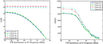
Figure 11. (Left) – Locata Signal Strength Indicator (LSSI) in the presence of CW interference. (Right) ENG1 in the presence of CW interference.
5.2. Positioning Solution Analysis
Carrier phase positioning is the main mode of positioning for Locata. After analysing the raw data, the final positioning solutions obtained using carrier phase measurements were analysed.
5.2.1. Carrier Phase Solution Analysis
Again, the positioning solution was obtained from measurements made in the presence and absence of introduced interference. WiFi-originated interference was used to analyse positioning solution corruption, as this is more likely to be the case in real-world scenarios. These results are shown in Figure 12. The residual error statistics are summarised in Table 2. Here the residual error can be defined as the difference between an instantaneous value and the mean of the whole data set. These statistics indicate the degree of noise present in the measurements. It can be noticed that interference induced errors in the positioning solution, raising the standard deviations of easting and northing components from under 2 mm to 15·44 mm and 14·21 mm respectively. The highest standard deviation is that of the height component, which is mainly due to higher values of VDOP. The corrupted positioning solution was determined to be 65·8 mm away from the true position. It can be seen from these figures that there were instances when the positioning solution was not corrupted very much. A possible explanation for this is that the interferer (WiFi radio in this case) does not transmit continuously. Locata uses Known Point Initialisation for resolving ambiguity. These resolved ambiguity values absorb all the un-modelled errors, including errors due to the received noise and interference. If the interference remains correlated over time, not much variation in the positioning solution is likely to appear. However, as this is not the case with WiFi-originated interference, relatively large variations can be noted in the final positioning solutions.

Figure 12. Carrier phase positioning solutions: (Left) in the ‘clean’ environment; (Right) in the presence of introduced interference.
Table 2. Carrier phase solution statistics in the absence and presence of introduced interference.
5.2.2. Code-Based Solution Analysis
When a carrier phase solution is not possible due to unavailability of ambiguity values or for any other reason, Locata can still provide a positioning solution using code-based pseudoranges. The quality of this solution was therefore also analysed in clean and noisy environments. The code loop is noisier than the carrier loop, and therefore a higher degree of measurement corruption can be expected. Figure 13 shows the code-based solutions in the presence and absence of interference. The residual errors are statistically summarised in Table 3. Again, WiFi-originated interference was used for testing as discussed in the previous section. The corrupted solution was found to be 15·12 metres away from the truth value, when averaged, with a standard deviation of 9·52 metres. The main solution corruption is in the height component, which was again the most affected component (compared to easting and northing). Similar observations can be made here, as were made for the carrier phase solution. Intervals can be observed when peak-to-peak solution variation remained within a band of a few metres. Again, as WiFi was used as the interferer, the same explanation is equally applicable here, i.e. its transmissions are intermittent instead of being continuous.

Figure 13. Code-based positioning solutions: (Left) in the ‘clean’ environment; (Right) in the presence of introduced interference.
Table 3. Code-based solution statistics in the absence and presence of introduced interference.
6. INTERFERENCE MITIGATION
The preceding analyses suggest that the measurements made by a rover receiver can be potentially corrupted in the presence of received interference. However, a number of techniques can be employed in order to avoid measurement quality degradation and/or solution corruption. Locata has recently released Version 3 devices. During the tests discussed in Khan et al. (Reference Khan, Dempster and Rizos2008a) it has been identified that there have been remarkable improvements in interference rejection in Version 3. It has also been noted that there is still room for improvement in terms of further interference rejection. Various Locata Network characteristics can be exploited to improve performance.
6.1. Dual-Frequency/Dual-Antenna System
As Locata uses dual-frequency and dual-antenna transmitters, frequency and spatial diversity can be exploited to achieve improvements. A Locata rover receiver makes four measurements from each LocataLite, of which three are redundant. If, for example, measurements are corrupted at one of the frequencies, the final positioning solution can still be obtained using measurements only from the other unaffected frequency carriers, even if the Locata Network operates with a minimum of four LocataLites. Also, in contrast to rejection of corrupted measurements, all four measurements can be used in the positioning solution after appropriate weighting. In Khan et al. (Reference Khan, Choudhury, Dempster and Rizos2009b) the authors have proposed a weighting technique that offers noise reduction in carrier phase measurements and hence an improvement in final positioning solution accuracy and precision. In addition to measurement weighting, the antenna diversity can be exploited to steer a null towards the interferer. This has not yet been implemented in this application.
6.2. TDMA Nature of the Signal
As WiFi and Locata both employ TDMA schemes for channel access, this fact can be exploited to force them to operate in a pseudo-synchronized manner, without any direct connectivity between systems. In Khan et al. (Reference Khan, Dempster and Rizos2008b) a novel scheme has been proposed to virtually eliminate WiFi-Locata inter-system interference. This not only offers control over Locata measurement quality but also allows WiFi to achieve acceptable throughput rates.
6.3. Presence of Multiple Carrier Tracking Loops
The rover receiver tracks four carriers at two different frequencies from each LocataLite. The carrier loops tracking these carriers can adaptively aid each other to maintain lock and avoid performance degradation in the presence of received RFI. To achieve this goal, the authors have proposed inter-loop aiding schemes in Khan et al. (Reference Khan, Dempster and Rizos2009a; Reference Khan, Dempster and Rizos2009c) with and without the use of a Kalman filter. These schemes can help in the reduction of carrier loops' total phase jitter, allowing operation at lower loop bandwidths which better facilitates operations in weak or interfered signal conditions.
7. CONCLUDING REMARKS
In this work the authors evaluated Locata performance in the presence of narrow- and wide-band interference. It was found that like any other system relying on wireless links, Locata performance can be affected by received interference. Locata performance was evaluated in detail by analysing raw measurement data as well as positioning solutions. The following conclusions can be drawn from the analyses:
• Locata performance can degrade in the presence narrow- as well as wide-band interference.
• WiFi has been identified as the potential interferer which may have both co-frequency and co-location issues with Locata devices.
• Locata has been shown to interfere with WiFi throughput. The WiFi-Locata problem is two-sided and any mitigation technique would have to consider improvements in both systems.
• Use of a smaller WiFi packet size, in addition to higher data rates, can help alleviate the interference issues.
• High levels of narrow-band interference can affect Locata's AGC and/or front-end operations. Locata performance can therefore be compromised even if the received RFI is not in co-frequency situation with a Locata carrier, depending on the received levels of interference.
• Raw measurements provided by Locata can be used to determine the extent of received interference, and mitigation techniques can be employed for reducing interference effects.
Although Locata has made significant improvements in interference mitigation in its latest version, there is still room for improvement. Several characteristics of Locata have been identified which can be exploited for interference mitigation. Proposals for more such schemes and the development of guidelines to avoid Locata performance degradation in the presence of RFI continue to be the goals of future work.
ACKNOWLEDGEMENT
This research is supported by Australian Research Council Linkage Projects LP0668907 and LP0560910.


