Introduction
Intensity-modulated radiotherapy (IMRT) is a well-established technique and is being widely used for the treatment of many cancer sites. In IMRT, highly conformal dose distribution can be achieved with the help of multileaf collimators (MLC), either by dynamic or step and shoot mode. In dynamic IMRT treatments, beam intensity modulation is achieved by MLC leaf motion with different speed at different locations and varying dose rate.
Accurate delivery of dynamic IMRT treatments depends on MLC leaf motion that has to move as per the planned trajectory and any mismatch may result in dosimetric uncertainties. The accuracy of MLC leaf positioning heavily depends on mechanical constraints of MLC, calibration, age of the motor, gravity effects, optical and radiation field congruence, latency of communication between MLC and controller.Reference Rangel and Dunscombe 1 It is important to understand the impact of MLC leaf positional errors on IMRT treatments, and regarding this only few studies are available in the literature.Reference Rangel and Dunscombe 1 – Reference Carver, Gilmore, Riley, Uzan and Mayles 8
Woo and NicoReference Woo and Nico 2 investigated the impact of MLC leaf end position variation on IMRT quality assurance (QA) using ion chamber measurements and showed that it can create a dose deviation up to 13%. Luo et al.Reference Luo, Li and Price 3 performed IMRT dose verification for prostate cancer using MLC log files obtained during dose delivery. They observed a linear correlation between average MLC position error and target dose, resulting in a dose error of about 1·0% to the target due to 0·2 mm systematic leaf position error. Zygmanski et al.Reference Zygmanski, Kung, Jiang and Chin 4 studied the relation between fluence errors and random leaf positional errors in dynamic IMRT and concluded that though the fluence variation arising from each single field was nearly >10%, average composite dose to the target of a nine-field IMRT plan was altered only by 3%. The impact of random and systematic MLC errors was investigated more intensively by Mu et al.,Reference Mu, Ludlum and Xia 5 and Rangel et al. calculated the tolerance value for MLC positional errors.Reference Rangel and Dunscombe 1
Sastre-Padro et al.Reference Sastre-Padro, Welleweerd, Malinen, Eilertsen, Olsen and van der Heide 6 studied the effects of systematic MLC positional errors on IMRT delivery and they concluded that these errors may compromise the treatment outcome. Yan et al.Reference Yan, Liu, Simon, Peng, Fox and Li 7 evaluated the sensitivity of IMRT QA procedures for detecting MLC positional errors using film and diode array and they found that only the errors >2 mm are detectable, and the diode array is more sensitive to these errors.
Most of the above studies focussed on either planning or delivery part of treatment. Moreover, the impact of MLC positional errors may be different in simple and complex IMRT plans. Therefore, the purpose of this study was to evaluate the dosimetric consequences of random and systematic errors in MLC positioning in brain (simple) and head and neck (HN) (complex) dynamic IMRT treatment plans through planning simulation. Furthermore, the capability of IMRT MatriXX device (Scanditronix Wellhöfer, Freiberg, Germany) was evaluated to detect the MLC leaf positional errors.
Materials and Methods
Planning
Five dynamic IMRT plans of each brain and HN, planned in Eclipse (version 8·6) treatment planning system (TPS) (Varian Medical Systems, Palo Alto, CA, USA) were retrospectively included in this study. Millennium 120 MLC (central 40 leaves having 5 mm width and peripheral 20 leaves having 10 mm width at the isocentre), attached to a clinical linear accelerator (CL2100CD, Varian Medical Systems) was used for creating intensity modulation. For brain IMRT plans, five fields were used, consisting of coplanar as well as non-coplanar beams. For HN IMRT plans, seven uniformly distributed coplanar fields were used. Dose calculation was performed using analytical anisotropic algorithm with a calculation grid size of 2·5 mm. The prescribed dose to the clinical target volume (CTV) was 54 Gy/30 fractions in brain cases and in HN cases simultaneous integrated boost technique was used to give 66 Gy/30 fractions to high-risk volume (CTV1), while 54 Gy/30 fractions was given to low-risk volume (CTV2). Direct volume optimisation was used for creating optimal fluence and then leaf motion calculator was used to convert this optimal fluence into actual deliverable fluence by accounting physical constraints of MLC and dose rate. These plans were termed as reference plans.
Error generation
Two types of MLC leaf positioning errors were introduced in each plan: random and systematic. Random errors were generated uniformly between −2.0mm and +2·0 mm (normal distribution), whereas systematic errors considered in this study were having the values: ±0·5, ±0·75, ±1·0 and ±2·0 mm. The plus sign (+) of systematic errors represents that both MLC banks move in outward direction (open MLC error), that is field size was increased; while for minus sign (–) both banks move in inward direction (close MLC error), that is field size was reduced. In order to introduce these errors, an interactive program was written in MATLAB software (version 7·0) (The MathWorks, Inc. Natick, MA, USA). The MLC files for each field of reference plan were exported from TPS to the program and the above-described errors were introduced to each moving MLC leaf. These modified MLC files were imported into the TPS and dose distribution was recalculated with the same number of monitor units (MUs) as in the reference plan. The plans with plus sign (+) and minus sign (−) systematic errors were termed as open MLC plans and close MLC plans, respectively. A total of nine plans were generated for each patient apart from the reference plan (50 plans for brain and 50 plans for HN).
Plan analysis
All the plans were compared with respective reference plans in terms of physical as well as biological doses to the target and organs at risk (OAR). However, MLC leaf error tolerance was decided based on the equivalent uniform dose (EUD), as physical quantities may not be reliable sometimes. A separate program was developed in MATLAB software to calculate EUD using the following formula:Reference Niemierko 9 , Reference Gay and Niemierko 10
 $${\rm EUD}{\equals}\left( {\mathop \sum\limits_{i{\equals}1} (v_{i} D_{i}^{a} )} \right)^{{1\,/\,a}} $$
where a is the model parameter (no unit), specific to normal tissues and tumour; v i is also unitless and represents partial volume (ith) that receives dose D i (Gy).
Furthermore, tumour control probability (TCP) and normal tissue complication probability (NTCP) were also calculated using the same software. Differential dose–volume histograms (DVH) of all plans were imported into the program for these calculations. The formulas used for TCP and NTCP are given below:Reference Niemierko 9 , Reference Gay and Niemierko 10
 $${\rm TCP}{\equals}{1 \over {1{\plus}\left( {{{{\rm TCD}_{{50}} } \over {{\rm EUD}}}} \right)^{{4\gamma _{{50}} }} }}$$
 $${\rm NTCP}{\equals}{1 \over {1{\plus}\left( {{{{\rm TD}_{{50}} } \over {{\rm EUD}}}} \right)^{{4\gamma _{{50}} }} }}$$
TCD50 is the tumour dose to control 50% of the tumours when the tumour is homogeneously irradiated. TD50 is the tolerance dose for normal structures at a 50% complication rate within a specific time interval for homogeneous irradiation. γ 50 is a unitless model parameter, specific to normal structure or tumour and describes the slope of the dose–response curve. The values of the parameters used are given in Table 1.
Table 1 The values of different parameters used in brain and HN for calculating biological parameters

Notes: a Model parameter specific to tumour and normal structures.
b Tumour dose to control 50% of tumour.
c Tolerance dose for normal tissues at 50% complication rate.
d Model parameter specific to tumour and normal structures.
Abbreviations: CTV, clinical target volume.
Evaluating IMRT MatriXX for detecting MLC errors
For evaluating the sensitivity of IMRT MatriXX to detect the MLC errors, known systematic positional errors, that is +0·5, +0·75, +1·0, +2·0, +3·0, +4·0 and +5·0 mm, were added to all the MLC in the MLC files of the reference plans. Here negative errors were not incorporated because negative error would create leaf overlapping which cannot be delivered. The error-introduced MLC files were imported into TPS and pre-treatment verification plans were calculated for two-dimensional (2D) ion chamber array system (IMRT MatriXX) using same number of MUs as in respective reference plans. All these QA plans were delivered on the linear accelerator (CL2100 CD equipped with Millennium 120 MLC) and the 2D fluences were measured using IMRT MatriXX device, which was placed at 5 cm depth (source to surface distance 95 cm) using slab phantoms. The error fluences were compared against the respective reference plans (no-error) using γ evaluation criteria of 2%/2 mm and 3%/3 mm.
Results
In this study the impact of random and systematic errors on MLC leaf positioning during dynamic IMRT delivery was evaluated for five brain and five HN cases.
Brain
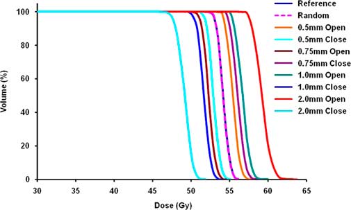
Figure 1 shows the cumulative DVH of CTV for all plans of one brain patient. The overall effect of MLC errors on brain patients is presented in Table 2 (physical parameters), and Table 3 presents average EUD for all brain patients. It was observed that the effect of random errors was negligible. On average the impact of random errors on CTV was –0·1±0·1% in terms of physical evaluation, as well as EUD. In case of OARs, the D max variation was within 0·2±0·2 Gy and ΔEUD was within 0·1±0·2 Gy for all organs. There was no significant difference in terms of TCP/NTCP.
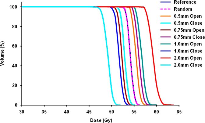
Figure 1 DVH of CTV for all plans of one brain case. Abbreviations: DVH, dose–volume histogram; CTV, clinical target volume.
Table 2 Average values of physical parameters (D 95 for CTV and D max for OARs) (mean ± SD) (Gy) for all five brain patients

Abbreviations: CTV, clinical target volume; OAR, organs at risk.
Table 3 Average EUD (mean ± SD) (Gy) for all five brain patients

Abbreviations: CTV, clinical target volume; EUD, equivalent uniform dose.
However, systematic errors had shown a considerable effect. Among two types of systematic errors, open MLC error increases OAR doses and close MLC error compromises target coverage. Hence, for targets the impact of close leaf errors and for OARs the impact of open leaf errors is discussed here. The impact of close leaf error on CTV was –2·5±0·7% for 0·5 mm when using physical evaluation and the same was –2·7±0·7% based on EUD. Similarly, the impact of 2 mm close leaf error was –10·4±3·4% when using physical evaluation and –10·7±3·1% based on EUD. TCP for the CTV was compromised by 0·8±0·2% for 0·5 mm close leaf error while the compromise was 4·2±1·9% for 2 mm close leaf error.
For OARs, the average variation observed for 0·5 mm open leaf errors was 1·5±0·3 Gy based on physical evaluation and the same was 1·8±0·4 Gy based on EUD. On the contrary, the change in physical doses and EUD for 2 mm open leaf errors was observed to be 5·7±1·8 Gy and 6·8±1·5 Gy, respectively. The maximum increase in NTCP was 1·5±2% for 0·5 mm MLC leaf error and 9·5±11% for 2 mm MLC leaf error. However, the large variations observed here were due to small structures in the brain; the variations observed for brain stem were much lower. The increase in NTCP for brain stem was 1·4±2·4% for 2 mm MLC leaf errors.
The average results for the sensitivity of IMRT MatriXX for MLC leaf positioning errors in brain patients are presented in Table 4. The impact of MLC errors was considered significant if <95% of pixels passed the γ-criteria for a particular MLC error. It was observed that as MLC error increased, γ pass rate decreased and 2%/2 mm γ-criteria was more beneficial in capturing the MLC errors compared to 3%/3 mm criteria. IMatriXX was able to detect more than 3 mm MLC errors if 2%/2 mm γ-criteria was used, while for 3%/3 mm γ-criteria, even a 5 mm MLC leaf error was not detectable.
Table 4 Percentage of pixels passing gamma test (mean±SD) for brain patients

Abbreviations: MLC, multileaf collimator.
Head–neck
Figure 2 shows the cumulative DVH of CTV for all plans of one HN patient. Table 5 shows the overall impact of MLC leaf errors on HN patients in terms of physical parameters, and Table 6 shows the biological parameters (average EUD for all HN cases). Similar to brain cases, the effect of random errors was observed to be negligible for HN cases. The maximum variation in physical doses to targets as well as OARs was 0·4±0·7% and 0·3±0·5 Gy, respectively. ΔEUD was within 0·5±0·7% for targets and within 0·2±0·4 Gy for OARs. In terms of TCP/NTCP, no significant difference was observed.
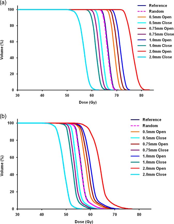
Figure 2 (a,b) DVH of CTV1 and CTV2 for all plans of one HN case. Abbreviations: DVH, dose–volume histogram; CTV, clinical target volume; HN, head–neck.
Table 5 Average values of physical parameters (mean ± SD) (Gy) for all five HN patients

Abbreviations: CTV, clinical target volume; HN, head–neck.
Table 6 Average EUD (mean ± SD) (Gy) for all five HN patients

Abbreviations: CTV, clinical target volume; EUD, equivalent uniform dose; HN, head–neck.
Among CTV1 and CTV2, the impact of closed leaf errors was more pronounced for CTV1 and based on physical evaluation it was −3·2±0·5% and based on EUD it was −3·5±0·6% (TCP decreased by 3·7±0·05%) for 0·5 mm, while the same varied up to −15·3±2·8% and −15·5±2·6%, respectively, for 2 mm (TCP decreased by 26·5±5·8%). The variation in maximum dose to serial structures (spinal cord and brain stem) was from 3·2±0·9 Gy (ΔEUD 2·4±1·0 Gy) for 0·5 mm to 12·4±3·3 Gy (ΔEUD 9·5±3·9 Gy) for 2 mm. Variation in mean dose to parotids was 1·8±0·4 Gy (ΔEUD 1·6±0·5 Gy) for 0·5 mm to 6·5±1·6 Gy (ΔEUD 6·2±1·8 Gy) for 2 mm. However, NTCP was not altered significantly due to MLC leaf errors and the differences in NTCP for all the critical structures were <1%.
The average results for the sensitivity of IMRT MatriXX for MLC leaf positioning errors in HN patients are presented in Table 7. Similar to brain cases, γ pass rate decreased with increase in MLC error and 2%/2 mm γ-criteria was better compared to 3%/3 mm. IMatriXX could be able to detect ≥2 mm MLC errors if 2%/2 mm γ-criteria was used, while for 3%/3 mm γ-criteria >3 mm errors were detected.
Table 7 Percentage of pixels passing gamma test (mean±SD) for HN patients

Abbreviations: MLC, multileaf collimator; HN, head–neck.
Discussion
In this study, dosimetric consequences of MLC leaf positioning errors on IMRT treatments were studied for five brain and five HN patients through planning simulation. Also, the sensitivity of IMRT MatriXX for MLC leaf positioning errors was experimentally analysed. The brain cases represent simple IMRT plans (average number of control points 554·4) and HN cases represent complex IMRT plans (average number of control points 1035·4). Random as well as systematic errors were added to the planned MLC trajectory using an in-house software program. The effect of these errors was evaluated in terms of both physical as well as biological parameters. A 2% change in target EUD and 2 Gy change in OAR EUD criteria was used by Rangel et al.Reference Rangel, Ploquin, Kay and Dunscombe 11 for evaluating the tolerance values of linear accelerator and the same criteria is also adapted here. The impact of random errors (±2 mm) was observed to be negligible in both sites and this justifies the tolerance value of 2 mm used for dynamic treatments using Varian MLC.
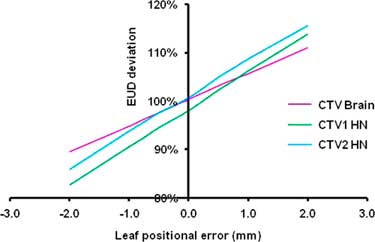
On the contrary, the impact of systematic errors was considerable. In order to find out the tolerance values for systemic MLC errors, graphs were plotted for targets and OARS with EUD on y-axis and MLC error on x-axis for brain as well as HN and one such graph for targets is shown in Figure 3.

Figure 3 Changes in target EUD due to systematic MLC leaf errors in brain (CTV) and HN (CTV1 and CTV2).
Since negative error impacts the target and positive error impacts the OARs, only these errors were taken into consideration for deriving the conclusion. Tolerance values were derived using interpolation and Tables 8 and 9 show the acceptable systemic MLC leaf errors for brain and HN, respectively. The MLC tolerance value for CTV in brain was found to be −0·36 mm, whereas for OARs it was observed to be 0·59 mm. The same in HN was −0·29 mm for targets, whereas 0·33 mm for OARs.
Table 8 Acceptable systematic MLC leaf errors (mm) for brain

Abbreviations: MLC, multileaf collimator; OARs, organs at risk.
Table 9 Acceptable systematic MLC leaf errors (mm) for HN

Abbreviations: CTV, clinical target volume; MLC, multileaf collimator; OARs, organs at risk; HN, head–neck.
The results of this study were in agreement with Rangel et al.Reference Rangel and Dunscombe 1 They analysed the dosimetric effect of random (±2 mm) and systematic [±1 mm (single/both banks) and ±0·5 mm (both banks)] errors in MLC leaf positions in seven prostate and seven HN dynamic IMRT plans. They concluded that random errors had no considerable impact but systematic errors should be limited to 0·3 mm for a maximum change in EUD of target by 2% and for OARs by 2 Gy.
It is evident from Figure 3 (slope is slightly more for HN compared to brain) and Tables 8 and 9 (tolerance values of HN are slightly less) that the impact of MLC errors is more on HN and this demonstrates that the effect of MLC error depends on the complexity of IMRT plan. Tatsumi et al.Reference Tatsumi, Hosono and Nakada 12 introduced systematic leaf errors in treatment plans generated by different TPS by changing the leaf offset in MLC controller. They assessed the impact of MLC errors in terms of pass rate of plan QA. They found that the average pass rate decreased with reduced mean leaf gap width (increased plan complexity) which supports the results of this study.
Mu et al.Reference Mu, Ludlum and Xia 5 also investigated the impact of MLC positional errors in HN. They concluded that random errors (±2 mm) had no meaningful impact while systematic errors (up to ±1mm) had significant effect and it was more pronounced for complex IMRT plans (at least 100 segments) compared to simple IMRT plans (maximum 50 segments). However, they used step and shoot IMRT planning using 10 mm MLC, whereas dynamic IMRT treatment with 5 mm MLC width was used in this study. Similarly, Budgell et al.Reference Budgell, Mott, Williams and Brown 13 also showed that MLC leaf position accuracy is more important for a highly modulated low-dose delivery than a moderately modulated high-dose delivery.
Though this study simulated the effect of wide range of systemic MLC leaf errors, such a large error may not be present during delivery. It is intuitive to know about actual MLC positional errors and their impact on delivered doses. For this purpose, each reference plan was delivered on the LINAC, and dynalog files were recorded that has information about the actual and planned MLC leaf motion.Reference Litzenberg, Moran and Fraass 14 An in-house program was developed using MATLAB software to convert the dynalog files into MLC files. These MLC files were imported into Eclipse TPS with respective fields and dose distributions were recalculated. The resulting EUD values along with the reference plan values for all brain patients are presented in Table 10 and for all HN patients in Table 11. It was observed that in brain the maximum EUD variation for CTV was <0·2%, whereas for OARs the maximum difference was 0·6 Gy for right optic nerve. In HN the maximum dose difference was 1·5% for CTV2 for second patient while among critical organs it was 1·1 Gy for spinal cord. These dose variations are slightly higher than that for random errors studied in this work but quite small compared to systematic errors.
Table 10 Impact of actual MLC leaf errors on brain cases

Abbreviations: CTV, clinical target volume; MLC, multileaf collimator; EUD, equivalent uniform dose.
Table 11 Impact of actual MLC leaf errors on HN cases

Abbreviations: CTV, clinical target volume; MLC, multileaf collimator; EUD, equivalent uniform dose; HN, head–neck.
During the IMRT MatriXX measurements, it was observed that MLC errors >3 mm were only detectable in case of brain, whereas for HN, ≥2 mm MLC errors were detectable with 2%/2 mm γ-criteria. This is in agreement with the results of Yan et al.Reference Yan, Liu, Simon, Peng, Fox and Li 7 They found that in γ analysis process 2%/2 mm criteria is more useful to detect these errors.
One of the limitations of this study is that only fixed-field IMRT plans were included for evaluation, while an investigation on rotational IMRT would be interesting. Recently, some studies have evaluated the impact of MLC errors on volumetric arc therapy (VMAT).Reference Oliver, Gagne, Bush, Zavgorodni, Ansbacher and Beckham 15 – Reference Coleman and Skourou 17 Oliver et al.Reference Oliver, Gagne, Bush, Zavgorodni, Ansbacher and Beckham 15 studied the impact of MLC positional errors (random as well as systematic errors of magnitude 0·25, 0·5, 1, 2 and 5 mm) on VMAT deliveries in HN. They concluded that the effect of MLC errors was similar to simple step and shoot IMRT plans (<50 segments) but much lesser than complex step and shoot IMRT plans (>50 segments) or dynamic IMRT plans. Furthermore, they suggested that in order to maintain planning target volume dose within 2%, MLC systematic errors should be within 0·6 mm.
Conclusion
In this study, the impact of MLC leaf positional errors in dynamic IMRT treatments was investigated. Random as well as systematic errors were introduced to planned MLC files by using in-house software. Systematic errors in MLC positioning showed considerable biological consequences whereas the random errors resulted in negligible effect. The impact of MLC leaf errors was slightly more on HN cases than brain cases. On the basis of results of this study, the acceptable systematic error was 0·4 mm for brain and 0·3 mm for HN.
Second, the sensitivity of IMRT MatriXX for MLC leaf positioning errors was experimentally analysed. The likelihood of error detection was observed to be more in HN than brain due to the complexity of the fluence. Further, the γ-criteria 2%/2 mm would be more beneficial in capturing these errors compared to 3%/3 mm. When using 2%/2 mm γ-criteria, the IMRT MatriXX device was able to detect the MLC errors ≥2 mm in HN and >3mm in brain during dynamic IMRT treatments.
Acknowledgement
None.
Financial Support
The authors declare no sources of funding.
Conflicts of Interest
The authors declare no conflict of interest.
Informed Consent
Informed consent was obtained from all individual participants included in the study.