I. INTRODUCTION
In recent years, circularly polarized (CP) antennas have gained more attention over the linearly polarized (LP) antennas. This transition is due to their unique characteristics, such as light weight, low profile, ease of mass fabrication, better mobility, and penetration features. So far, considerable researches have been conducted on the design of CP antennas. It is well known that CP is generated by exciting two orthogonal electric field vectors on the antenna body. Different techniques have been applied to excite two orthogonal modes, which end in different array topologies. For instance, adoption of dual strip sleeves shorted at the ground plane [Reference Lu and Huang1], excitation of electric field with the same amplitude with 90° phase difference on vertical and horizontal paired slots [Reference Liu, Zhu and Choi2], adoption of two ports for dual circular polarization operation [Reference Ferreira, Joubert and Odenadaal3], benefitting the CP characteristics of spidron fractal slot and patch antennas [Reference Altaf, Yang, Lee and Hwang4], adoption of diagonal line slots [Reference Awaludin, Sumantyo, Santosa and Baharuddin5], adoption of L-shaped stub and controlling the excitation phase [Reference Ghaffarian, Moradi and Mousavi6], modified feeding and symmetric ellipse aperture [Reference Li, Wang, Li and Yang7], using twin diamond-shaped patch and a gap-coupled feed structure [Reference Li, Ren, Yin, Chen and Wang8], and adoption of wide symmetrical slot and aperture along the diagonal axis [Reference Nasimuddin, Chen and Qing9, Reference Nasimuddin, Chen and Qing10] are some of the methods to realize CP feature. On the other hand, adoption of array structures in antenna design processes has revealed great opportunities to enhance the technical functionalities. In this context, remarkable studies are conducted to design CP printed slot antenna arrays with various array elements and feeding mechanisms. Benefitting from the excellent features of both CP and array antennas, the CP array structures make a great sense in communication systems. Similar to single CP antennas, to attain the CP characteristics in array antennas, two or more orthogonal LP modes should be excited in equal amplitudes but in phase quadrature. Moreover, array element selection, elements spacing, and feeding mechanism are some of the critical issues that influence the final performance of CP array structures. Although there have been many CP array antennas with suitable and remarkable characteristics, there are still some challenges in this area [Reference Rahman, Hossain, Azad Hossain, Nishiyama and Toyoda11–Reference Li, Zhang and Feng17]. Acquiring wider impedance and axial-ratio (AR) bandwidths, increasing the CP purity, miniaturizing the structures, and enhancing the feeding strategy quality of the CP array antenna are some of the most important ones. So far, many different feeding techniques have been adopted in CP array antennas to achieve suitable performance. One of the most promising ones is the sequential phase (SP) feeding mechanism, which has proved to enhance the functionality of 2 × 2 array antennas [Reference Lin and Lin18, Reference Deng, Li, Zhang and Feng19].
Stimulated based on the aforementioned discussion, this paper aims at designing novel designs of CP single and array antennas, evolved for C- and X-band applications. The single CP elliptical slot antenna (CPESA) is composed of simple feed line, two linked elliptical slots, and a combination of rectangular stubs and slots. Suitable impedance and AR bandwidth are obtained for the CPESA. Moreover, the proposed 2 × 2 CP elliptical slot array antenna (CPESAA) configuration is composed of four CPESAs as the array elements. As well, aiming at benefitting from the advantages of the aforementioned SP feed, this feeding strategy is utilized in the present array configuration. Through a suitable placement of array elements and an appropriate feeding approach, wide band impedance and AR bandwidths are granted. As well, 4 × 4 CPESAA is composed of 16 simple CPESAs with SP feed network. This configuration, exhibits wider impedance and AR bandwidth as well as higher gain values with respect to 2 × 2 CPESAA. The remainder of the paper is organized as follows: Section II introduces the design process and performance of the single CPESA design. As well, comparison of structural and operational characteristics of the proposed CPESA with some similar previously designed structures is conducted in this section. Section III surveys the SP feeding strategy utilized in proposed array antennas. Section IV discusses the design process of 2 × 2 CPESAA. Simulated and measured results regarding the presented structure and comparison with some previous designs are discussed. In the sequel, Section V presents the 4 × 4 CPESAA performance. Ultimately, Section VI concludes the paper.
II. SINGLE ANTENNA DESIGN AND PERFORMANCE
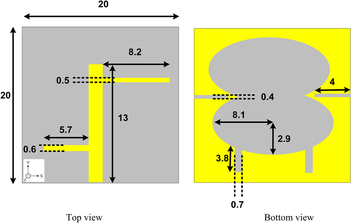
This section intends to introduce the single CPESA, which is utilized as array element. The geometry of the proposed CPESA is shown in Fig. 1. It is seen that the antenna is composed of a simple rectangular feed line to which two rectangular stubs are attached. On the backside of the substrate also, two linked elliptical and rectangular slots along with two other rectangular slots on two sides are included. The final design is achieved by applying step-by-step modifications in CPESA design. First, just a simple rectangular feed line on top side and two linked elliptical slots are included on backside (Ant. 1). Then, the lower rectangular stub is attached to feed line (Ant. 2). In the sequel, the rectangular slots on backside of the substrate are embedded (Ant. 3). Afterwards, the upper rectangular stub is added to the feed line configuration (Ant. 4). Ultimately, the lower side rectangular slots are pinned to the backside linked elliptical slots (Ant. 5). Simulated S 11 and AR curves of the aforementioned structures are extracted using Ansoft High-Frequency Structure Simulator (HFSS) and plotted in Fig. 2. It is clearly seen that in Ant. 1, no 10-dB impedance bandwidth and no CP is obtained. In Ant. 2, by including the lower rectangular stub on the feed line, operating bandwidth of 6–7 GHz with CP at 5.5–6 GHz is obtained. In the sequel, by including the rectangular slots on backside, the upper operating frequency extends to 7.4 GHz, which exhibits 5.75–7.2 GHz CP feature. The inclusion of upper rectangular stub in feed line of Ant. 4 extends the 10-dB operating bandwidth to 4.6–6.5 with CP at 5–6.4 GHz. Finally Ant. 5, which is the final structure, operates over the frequency band of 4.4–8 GHz and CP at 4.4–6.5 GHz.

Fig. 1. Geometry of the proposed CPESA.

Fig. 2. (a) S 11 curves and (b) AR curves for the five antennas in the CPESA design process.
To shed light on the advantages of the proposed design, a comprehensive comparison is carried out between the present CPESA and some of the previously designed CP antennas. Table 1 reports the operational and structural features of the proposed CPESA and those of the structures in [Reference Altaf, Yang, Lee and Hwang4–Reference Nasimuddin, Chen and Qing10]. The comparison points include total size, 10-dB impedance bandwidth, 3-dB AR bandwidth, and peak gain values. As the provided data unveil, proposed CPESA occupies the smallest area among the other configurations, this is while; the operating 10-dB impedance bandwidth and 3-dB AR bandwidths are laid in a suitable and acceptable frequency range. As array antennas are composed of hundreds of thousands of single antennas, the array element size issue becomes very critical and important. The present CPESA, by offering marvelous merits, such as small size, and suitable operating bandwidth and gain, is selected to be used in array form.
Table 1. Structural and operational characteristics of the proposed CPESA and some similar previously designed CP structures.
III. FEEDING STRATEGY
The influential effect of the feeding mechanism is an inevitable fact in antenna systems. Hence, selection of effective and suitable feed is an important step to achieve the desired output in antenna design process. In simple antennas, usually a simple feed line could meet the requirements and yield in the desired results. However, in array antennas, due to the presence of hundreds of single antennas, feeding issue becomes more critical and complex. So far, many feeding techniques have been utilized in antenna arrays. Among different feeding mechanisms, SP feeding is one of the most promising techniques, especially in CP antenna arrays which lead to polarization purity increment, impedance matching, and pattern symmetry. As well, it is well known that microstrip antennas inherently suffer from narrow bandwidth. Adoption of SP feed network not only enhances the CP quality of the arrays, but also helps to get wider impedance bandwidth. To benefit from the advantages of SP feed, this technique is adopted in the present array antennas, which improve the overall antenna performance. Detailed studies on design process of SP feed configuration are presented in [Reference Lin and Lin18–Reference Evans, Gale, Aljibouri, Lim, Korolkwiwicz and Sambell20].
IV. THE 2 × 2 ARRAY ANTENNA
Figure 3 demonstrates the implanted CPESA array elements as four slot CP antennas. With respect to Fig. 3, it can be seen that the proposed CPESAA consists of four sequentially rotated CPESA elements and a feed network. Low-cost FR4 substrate with ε r = 4.4, tanδ = 0.02, and thickness of 1 mm is employed in fabrication of the CPESAA. A simple 50 Ω microstrip line with the width and length of 1.86 and 13.45 mm is deployed to excite the array antenna. The commercial Ansoft™ HFSS software is used to simulate and optimize the CPESAA configuration. To deeply investigate the CPESAA design, the design procedure is discussed in three steps. First, four microstrip feed lines along with paired overlapping elliptical slots are embedded in the ground plane (Ant. 1). Next, with the aim of exciting two orthogonal E vectors to attain the CP characteristics, eight perpendicular stubs in four branches are embedded in the feed network (Ant. 2). Four rectangular slots are also removed from each array element (Ant. 3). Simulated and measured S 11 and AR curves of the three aforementioned antennas are plotted in Fig. 4. It is clearly seen that Ant. 1 operates in four frequency bands including 4.2–5.2, 6.4–6.7, 7.4–7.7, 8.5–9 GHz with CP at 4.65–4.85 GHz. In Ant. 2, the obtained 10-dB impedance bandwidth is 4.5–7.2, 7.8–8.5, and 8.9–9.5 GHz, and CP is observed in 4.75–5.35, 5.8–6.3, and 7–7.4 GHz. Finally, in Ant. 3, 4.18–9.35 GHz is covered by the antenna and CP is obtained in 4.49–7.62 GHz.

Fig. 3. The 2 × 2 CPESAA design process denoted as Ant. 1, Ant. 2, and Ant. 3.

Fig. 4. (a) S 11 curves and (b) AR curves for the three antennas in the 2 × 2 CPESAA design process.
Wise inclusion of eight stubs and removal of four rectangular slots paves the way to achieve the CP features by the presented design. Based on the coupling conditions between the strip feedline and overlapped elliptical slots, embedding the rectangular slots in the substrate leads to a capacitive loading condition. Thus, the electrical length of the proposed slot antenna is increased. This point improves the electromagnetic coupling between the feedline, and the ground plane increases the impedance bandwidth without any cost or size increment.
The 2 × 2 CPESAA occupies a small area of 55 × 60 × 1 mm3 and operates over the frequency range of 4.18–9.35 GHz with circular polarization at 4.49–7.62 GHz for C-band application.
The final optimized parameters of the proposed CPESAA are as follows: L g = 60, W g = 55, L 1 = 13.45, W 1 = 1.86, L 2 = 13.45, W 2 = 1.86, L 3 = 13.45, W 3 = 1.86, L 4 = 13.45, W 4 = 1.86, L 5 = 13.45, W 5 = 1.86, L 6 = 13.45, W 6 = 186, L 7 = 13.45, W 7 = 1.86, L 8 = 13.45, and W 8 = 1.86.
An experimental prototype of the fabricated 2 × 2 CPESAA is shown in Fig. 5. For the proposed structure, measured and simulated results of impedance bandwidth, AR, and gain are presented in Figs 6(a) and 6(b). The S 11 and AR of the proposed antenna array are measured by Agilent 8722ES network analyzer. Based on the simulated results, the proposed antenna exhibits impedance bandwidth of 76.4% from 4.18 to 9.35 GHz. Similarly, the measured impedance bandwidth preserves 76.4% from 4.18 to 9.35 GHz for S 11 < −10 dB. The 3 dB AR bandwidth of 51.4% is also obtained for the presented antenna from 4.49 to 7.62 GHz. A standard LP horn antenna is used to measure the total gain characteristics of the proposed design. The obtained gain values lie within 5–9.7 dBic across the operating band with the peak value of 9.7 dBic at 6.4 GHz.

Fig. 5. Photograph of the fabricated 2 × 2 CPESAA.

Fig. 6. (a) Simulated and measured S 11 of the proposed 2 × 2 CPESAA and (b) simulated and measured gain and AR of the proposed 2 × 2 CPESAA.
As well, surface current distribution is studied at 4.8 GHz for the 2 × 2 CPESAA in 0°, 90°, 180°, and 270°. As it is clearly shown in Fig. 7, the magnitudes of the current in 180° and 270° are similar to the current in 0° and 90°, but the phases are distributed in opposite directions. Based on the simulated results in Fig. 4, the 2 × 2 CPSAA exhibits right-hand circular polarization (RHCP) in the +z direction and left-hand circular polarization (LHCP) in the −z direction.

Fig. 7. Distribution of the surface current on the feed and ground plane of the CPESAA: (a) 0°, (b) 90°, (c) 180°, (d) 270°.
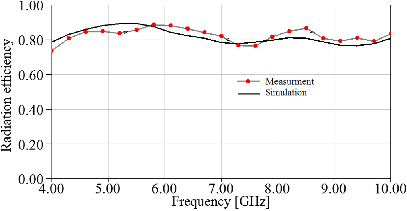
Simulated and measured efficiency of the proposed 2 × 2 CPSAA is plotted in Fig. 8. The simulated and measured results confirm each other indicating an efficiency of around 80% over the operating frequency range. The measured results of the normalized RHCP and LHCP radiation patterns of the array at two frequencies 4.8 and 6.8 GHz are portrayed in Fig. 9. The obtained results confirm outperformance of the proposed design. Moreover, the proposed structure is compared against some of the archived designs with sequential feed network. Results are demonstrated in Table 2. As can be seen, the proposed design not only yields in an improved technical performance but also reveals a significant decrease in total size.

Fig. 8. Simulated and measured efficiencies of the proposed 2 × 2 CPESAA.

Fig. 9. Measured RHCP and LHCP radiation patterns at 4.8 and 6.8 GHz: (a) 4.8 GHz, (b) 6.8 GHz.
Table 2. Comparison of the proposed CPESAA size and measured characteristics against some other structures.

V. THE 4 × 4 ARRAY ANTENNA
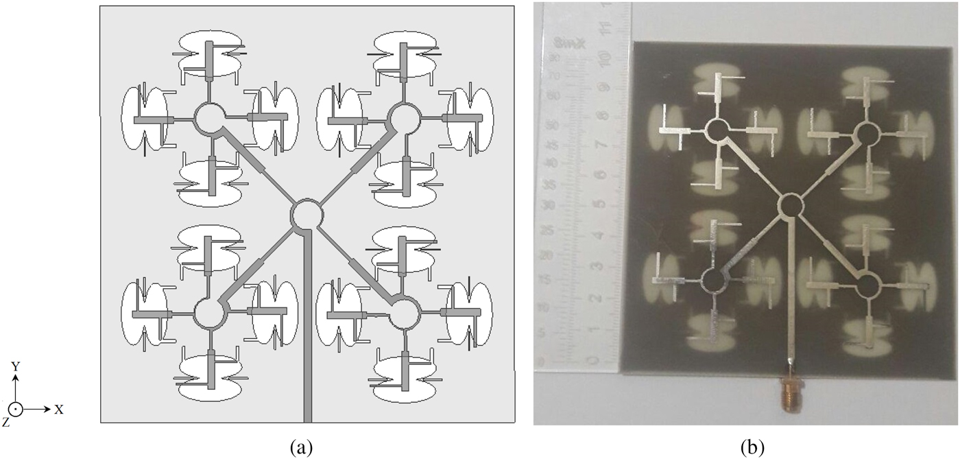
With the aim of further performance enhancement, a 4 × 4 CPESAA composed of 16 single CPESA is designed and studied in this section. Figure 10 shows the schematic view and fabricated prototype of the proposed 4 × 4 CPESAA. As it is seen, 16 CPESAs in the form of four 2 × 2 CPESAAs are arranged to generate the array structure. As discussed in previous sections, SP feed technique is adopted to excite the array configuration. The 4 × 4 CPESAA is printed on FR4 substrate with the overall size of 110 × 110 × 1 mm3. To assess the performance of the proposed configuration in real condition, an experimental prototype is measured in the antenna and microwave laboratory regarding S 11, AR, and gain.

Fig. 10. (a) Schematic view of the proposed 4 × 4 CPESAA, and (b) fabricated prototype.
Figure 11(a) displays the simulated and measured S 11 results, which confirm that 4 × 4 CPESAA operates over the frequency range of 1.15–12.98 GHz. As well, AR and gain of the 4 × 4 CPESAA is depicted in Fig. 11(b). Large CP bandwidth is achieved in the frequency range of 2.95–8.82 GHz. As it is seen, 4 × 4 CPESAA exhibits enhanced performance against the 2 × 2 one regarding S 11, AR, and gain. Herein, gain values are around 12 dBic, while in the previous 2 × 2 design, maximum gain value is 9.7 dBic. It could be concluded that by increasing the array elements number, impedance bandwidth and gain are improved significantly.

Fig. 11. (a) Simulated and measured S 11, and (b) simulated and measured AR and gain.
VI. CONCLUSION
This paper tailored an efficient design of 2 × 2 and 4 × 4 CPESAAs using mutually overlapping elliptical slots element. Inclusion of two linked elliptical slots at each array element along with eight stubs in sequential rotation feedline and also removal of four rectangular slots from edges of each slot yielded in enhancement of return loss and AR bandwidths in 2 × 2 CPESAA configuration. As well, the proposed 4 × 4 CPESAA was composed of 16 single CPESAs. This structure exhibited wider impedance bandwidth, AR, and gain with respect to 2 × 2 design. A remarkable reduction in size and implementation space, wider impedance, and AR bandwidth were reflected as some of the interesting features of the proposed designs against the previous CPESAAs.
 Saeed Mohammadi-Asl was born in Urmia, Iran 1984. He received his B.Sc. and M.Sc. degrees in Electrical (Telecommunication) from the Urmia University, Urmia, Iran in 2008 and 2010, respectively. His primary research interests are in antenna design, numerical methods in electromagnet microwave components.
 Javad Nourinia received his B.Sc. degree in Electrical and Electronic Engineering from the Shiraz University and M.Sc. degree in Electrical and Telecommunication Engineering from the Iran University of Science and Technology, and Ph.D. degree in Electrical and Telecommunication from the University of Science and Technology, Tehran Iran in 2000. From 2000, he was an Assistant Professor and now he is a Professor in the Department of Electrical Engineering of the Urmia University, Urmia, Iran. His primary research interests are in antenna design, numerical methods in electromagnetic, microwave circuits.
 Changiz Ghobadi was born on June 1960 in Iran. He received his B.Sc. degree in Electrical Engineering Electronics and M.Sc. degree in Electrical Engineering Telecommunication from the Isfahan University of Technology, Isfahan, Iran, and Ph.D. degree in Electrical-Telecommunication from the University of Bath, Bath, UK in 1998. From 1998, he was an Assistant Professor and now he is a Professor in the Department of Electrical Engineering of the Urmia University, Urmia, Iran. His primary research interests are in antenna design, radar, and adoptive filters.
 Maryam Majidzadeh was born on 18 September 1987 in Urmia, Iran. She received her Ph.D., M.Sc., and B.Sc. degrees in Electrical Engineering from the Urmia University in 2016, 2012, and 2009, respectively. Now she is an Assistant Professor in the Department of Electrical and Computer Engineering, Urmia Girls Faculty, West Azarbaijan branch, Technical and Vocational University (TVU), Urmia, Iran. Her research interests are in electromagnetic compatibility, frequency selective surfaces, designing of UWB antenna, bandwidth enhancement and antenna miniaturization techniques, circularly polarized antennas and numerical method in electromagnetics.