


I. INTRODUCTION
With the rapid development of radio frequency (RF) and microwave systems, various types of power dividers have been developed to realize the power divider/combing [Reference Xue, Song and Chan1–Reference Li, Liu, Li, Yu and Wu27]. The waveguide-based power dividers have been widely investigated and used in microwave and millimeter-wave systems because of their low insertion loss, high-power capability, and wide bandwidth [Reference Ahmadzadeh, Rasekh, Safian and Askari2–Reference Becker and Oudghiri13]. While the substrate integrated waveguide (SIW) and planar power dividers have advantages of easy integration with monolithic microwave integrated circuit (MMIC), good impedance matches at all ports and high isolation among the output ports [Reference Eom, Byun and Lee14–Reference Li, Liu, Li, Yu and Wu27]. Among the planar power dividers, the Bagley Polygon power divider is an input impedance match N-way (N is odd) circuit. Compared with the Wilkinson power divider, the Bagley Polygon power divider does not use lumped elements and can be easily extended to arbitrary odd number of output ports. Therefore, this kind of power divider is suitable for antenna feeding networks, power combing networks, and multiplexers, etc.
However, the disadvantage of the Bagley Polygon power divider is its large size. In order to solve this problem, a five-way miniaturized power divider was proposed in [Reference Sakagami, Wuren, Fujii and Tahara25]. The length of the transmission line (TL) between the output ports can be tuned according to the requirement, but the isolation performance has been ignored. Moreover, the realizable N is limited by the high-impedance TL. In [Reference Li, Zhao, Zhang and Xu26], the defected ground structure (DGS) technology is utilized for miniaturization. However, this circuit suffers from the difficulty in assembling. In [Reference Li, Liu, Li, Yu and Wu27], a miniaturized three-way Bagley Polygon power divider was proposed by using the dual TLs, but it also ignores the isolation performance. Moreover, the high-impedance TL used in the circuit will lead to the same problem that occurs in [Reference Sakagami, Wuren, Fujii and Tahara25]. In addition, more analysis is needed when the number of output port N is changed.
In this paper, a three-way miniaturized Bagley Polygon power divider is implemented based on the composite right/left-handed (CRLH) TL. The proposed power divider not only realizes the size reduction, but also maintains the isolation between the output ports. It is observed that simulated and measured results show a good agreement.
II. ANALYSIS AND DESIGN OF THE POWER DIVIDER
Figure 1 shows the circuit layout of the conventional Bagley Polygon power divider, which is composed of two λ/2 length TLs and two λ/4 length TLs. Based on the theory in [Reference Sakagami, Wuren, Fujii and Tahara25],
 $Z_a = 2Z_0/\sqrt 3 $
, while Z
b
is arbitrary. The output of the power divider is equal in amplitude. The phase of port 2 and port 3 is same and out-of-phase with port 4. The power divider shows 10-dB isolation performance between the three output ports [Reference Oraizi and Ayati23]. In this paper, the two λ/2 length TLs are replaced by 0° TLs.
$Z_a = 2Z_0/\sqrt 3 $
, while Z
b
is arbitrary. The output of the power divider is equal in amplitude. The phase of port 2 and port 3 is same and out-of-phase with port 4. The power divider shows 10-dB isolation performance between the three output ports [Reference Oraizi and Ayati23]. In this paper, the two λ/2 length TLs are replaced by 0° TLs.

Fig. 1. The circuit of conventional Bagley Polygon power divider.
The 0° phase shift TL is realized by the CRLH and conventional microstrip TL. The CRLH TL provides the positive phase shift, and the latter provides the negative phase shift. Figure 2(a) shows the structure of the CRLH part. Figure 2(b) is the equivalent circuit of the CRLH TL. Interdigital capacitor provides the left-handed capacitor C L . The short-ended stubs provide the left-handed inductors L L . Based on the theory in [Reference Ren, Song, Fan, Zhu and Hu22], the phase response of the CRLH TL can be calculated by equation (1):
 $$\eqalign{\varphi & = \pm n \times \arccos [ {1 - ({\omega ^2L_RC_R + 1/\omega ^2C_LL_L} )} \cr & \quad + {({C_R/C_L + L_R/L_L})}],}$$
where the “±” sign denotes that the phase shift is negative in the left-handed band and positive in the right-handed band, n is the number of the CRLH cells; ω is the angular frequency. In order to apply this structure into the circuit, the impedance must be equal to Z b . The impedance of the CRLH TL can be calculated by equation (2):
 $$Z_B = \displaystyle{{ \pm \left( {j\omega L_R + {1 / {j\omega C_L}}} \right)} \over {\sqrt {{\left[ {1 + \left( {{1 / {j\omega L_L}} + j\omega C_R} \right)\left( {{1 / {j\omega C_L}} + j\omega L_R} \right)} \right]}^2 - 1}}}, $$
where Z B indicates the Bloch impedance. Based on the CRLH TL theory, the balance condition is
 $$L_RC_L = L_LC_R = {1 / {\omega _0^2}}, $$
where the ω 0 is the center angular frequency. Based on the balance condition, the equation (2) can be simplified to
 $$\sqrt {{{L_L} / {C_L}}} = \sqrt {{{L_R} / {C_R}}} = Z_B.$$

Fig. 2. (a) The structure of the CRLH TL. (b) Equivalent circuit of the CRLH TL.
The Z B should be equal to Z b . In reality, the phase response of the CRLH TL (φ) should be set bigger than 0. The CRLH structure should connect with other part of the power divider through the microstrip TL, which will introduce some negative phase shift. The structures of the miniaturized Bagley Polygon power divider and the 0° TL are shown in Fig. 3. The dimensions of CRLH TL in Fig. 3 are as same as in Fig. 2.

Fig. 3. Circuit layout of the miniaturized Bagley Polygon power divider.
If the φ and C L are given, the parameters C R , L L , and L R can be calculated based on the equations (1), (3), and (4). The other part of the power divider is same as the conventional type as shown in Fig. 1. The C L can be implemented based on the empirical equation [Reference Caloz and Itoh28]:
 $$C_L \approx (\varepsilon _r + 1)l\left[ {\left( {N - 3} \right)A_1 + A_2} \right].$$
Here,
 $$A_1 = 4.409\;\tanh \left[ {0.55{\left( {\displaystyle{h \over {\omega _f}}} \right)}^{0.45}} \right](pF/\mu {\rm m})$$
 $$A_2 = 9.92\;\tanh \left[ {0.52{\left( {\displaystyle{h \over {\omega _f}}} \right)}^{05}} \right](pF/\mu {\rm m}),$$
where, ε r is the dielectric constant of the substrate; l, N, and ω f denote the length (l f ), number, and width of the interdigital line, respectively; h is the height of the substrate.
III. EXPERIMENT AND RESULTS
For experimental demonstration, the proposed miniaturized Bagley Polygon power divider is designed and fabricated on substrate Taconic RF-35 with dielectric constant of 3.5, thickness of 0.508 mm, and loss tangent of 0.0018. The center frequency is 3.5 GHz. According to above design procedure, the initial dimensions of the proposed power divider can be obtained firstly. Then the HFSS (high frequency structural simulator, a commercial finite element method solver for electromagnetic structures from Ansys) is utilized to simulate and optimize. After optimization, the final sizes of the power divider are: L 1 = 16.9 mm, L 2 = 4 mm, L 3 = 3.4 mm, W 1 = 0.87 mm, W 2 = 0.6 mm, l s = 5.4 mm, w s = 0.2 mm, g = 0.15 mm, S = 0.15 mm, l f = 4 mm, w f = 0.2 mm, D = 0.5 mm. The λ/4 sections are bended to further reduce the total size. The fabricated Bagley Polygon power divider is shown in Fig. 4.

Fig. 4. Photograph of the fabricated Bagley Polygon power divider.
The simulated and measured results of the fabricated Bagley Polygon power divider are shown in Fig. 5. It can be seen that the measured results show a reasonable agreement with the simulated ones. The input return loss is >15 dB in the center frequency. The maximum insertion loss between the three output ports is 4.89 dB (4.77 + 0.12 dB). Figure 5(a) shows the good amplitude imbalance at the center frequency. Figure 5(b) shows that the S 23, S 24, and S 34 are 10.12, 9.27, and 10.14 dB, respectively, which demonstrates that the miniaturization does not deteriorate the isolation performance of this type of power divider. In this design, the 0° phase shift TL is utilized to replace the 180° TL. Based on the TL theory, the output ports should be in-phase instead of out-of-phase. Figure 6 demonstrates the success of the design method, although there is some imbalance between the three output ports. As for imbalance at 3.5 GHz between the fourth and the other output ports, some measurement error may cause it and make the in-phase frequency deviate from the 3.5 GHz. To the point, it has no effect on the performance of the power divider.

Fig. 5. Simulated and measured results of the fabricated power divider. (a) Insertion loss and return loss; (b) isolation.
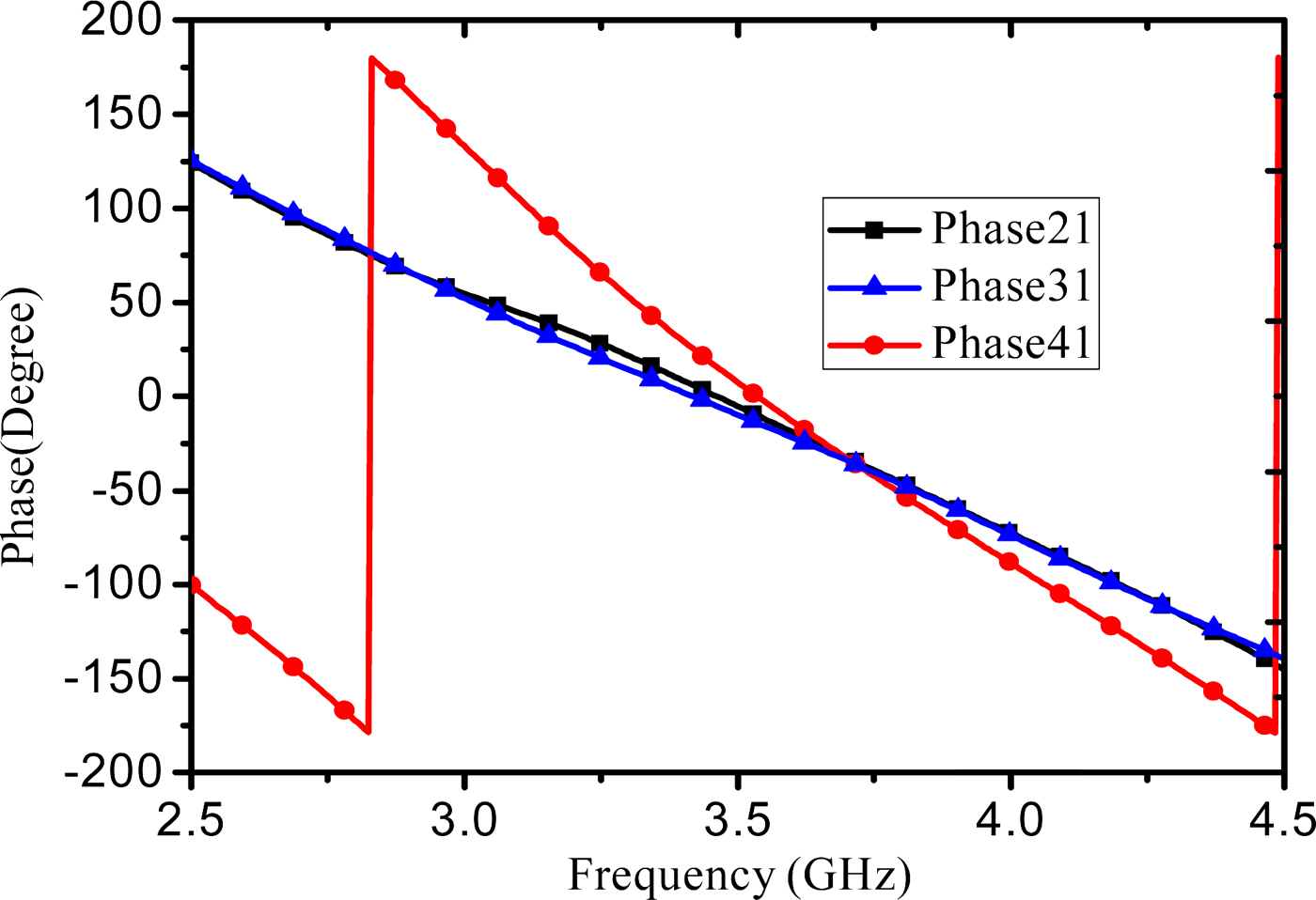
Fig. 6. Measured phase response of the miniaturized Bagley Polygon power divider.
In addition, the number of the output ports can be added by simply inserting the 0° phase shift TL between the two arbitrarily adjacent output ports without other calculation or extra analysis. It also avoids the limitation of the realizable impedance during the fabrication. Table 1 compares the performance of the proposed design and other miniaturized Bagley Polygon power dividers reported in recent years. It demonstrates that the proposed power divider has realized the significant size reduction and maintained its isolation performance. Although the size of the proposed power divider is larger than that in [Reference Li, Liu, Li, Yu and Wu27], our work features easier assembly and isolation maintained.
Table 1. Comparison with some prior miniaturized Bagley polygon power divider.

* The ratio of the size of proposed power divider and the size of the conventional Bagley Polygon PD (λg/2*λ g/4); IL, insertion loss.
IV. CONCLUSION
In this paper, a miniaturized Bagley Polygon power divider by using the CRLH TLs has been proposed. The working mechanism about the power divider and the function about the CRLH TLs have been presented and analyzed. The design equations have been presented. The major advantages of the proposed Bagley Polygon power divider are its compact size, the preservation of its intrinsic isolation performance, and the simple design method. Good agreement between the simulated and measured results has been observed.
ACKNOWLEDGEMENT
The work for this grant was supported by National Natural Science Foundation of China (Grant No: 61271026).
 Kaijun Song (M'09–SM'12) received the M.S. degree in Radio Physics and the Ph.D. degree in Electromagnetic Field and Microwave Technology from the University of Electronic Science and Technology of China (UESTC), Chengdu, China, in 2005 and 2007, respectively. Since 2007, he has been with the EHF Key Laboratory of Science, School of Electronic Engineering, UESTC, where he is currently a full Professor. His current research fields include microwave and millimeter-wave/THz power-combining technology; UWB circuits and technologies; microwave/millimeter-wave devices, circuits, and systems; and microwave remote-sensing technologies. Prof. Song is the Reviewer of tens of international journals, including Scientific Reports, IEEE Transactions, and IEEE Letters.
 Te Kong was born in Zhejiang, China in 1994. He received his Bachelor of Engineering degree in Electrical Engineering from the University of Electronic Science and Technology of China (UESTC) in 2016. To date, he is working toward the Master degree in University of Electronic Science and Technology of China. His current research interests include microwave/millimeter-wave devices, circuits, and systems.
 Yu Zhu was born in Anhui, China in 1992. He received his Bachelor of Engineering degree in Electrical Information Engineering from Southeast University Chengxian College in 2014, and now he is trying to obtain his Master degree in Electrical Engineering in the University of Electronic Science and Technology of China (UESTC). His current research interests include millimeter-wave techniques with a focus in RF/microwave passive.


