


I. INTRODUCTION
In the era of tremendous development in the wireless communications, design of low-profile multi-band antennas has attracted great attention due to their capability of integration in portable devices. There are several attractive features of a coplanar waveguide (CPW)-fed antenna-like uniplanar structure such as good impedance matching, multi-band operation, and ease of implementation and integration with MMIC (monolithic microwave integrated circuits). Based on CPW-feeding structure, various techniques have been recently proposed and presented in literature to support dual-, triple-, or multi-band operation for standard applications such as, global position system (GPS), wireless local area network (WLAN), and worldwide interoperability for microwave access (WiMAX) [Reference Xin and Xu1–Reference Liu, Zou, Xie, Liu and Sun13]. The most common technique focuses on modifying the geometry of the radiating patch or/and employing defected ground structure. G-shaped radiating structure is configured for dual-band operation [Reference Xin and Xu1]. For tri-band operation, a fork-shaped antenna [Reference Xu, Xin and He2], and M-shaped meander-line antenna [Reference Zahraoui, Zbitou, Errkik, Abdelmounim, Tajmouati and Latrach3] have been introduced. In addition, some modifications in the feeding structure like rhombic ring feeding structure in the open end of the CPW feed line [Reference Lin, Yu and Huang4] or etching slots [Reference Basaran and Sertel5–Reference Zhang, Jiao and Wang7] have been used to generate multiple resonant modes. Other methods to produce multiple resonate modes are by extending resonance branches or adding parasitic resonators to provide several current paths. These techniques include loading the antenna with an additional V-shaped sleeve [Reference Augustin, Bybi, Sarin, Mohanan, Aanandan and Vasudevan8], an inverted U-shaped strip [Reference Liu, Song, Chung and Jaw9], handstand stubs to ground plane aperture [Reference Luo, Xu, Xin and He10], a parasitic E-shaped strip [Reference Shu and Feng11], and a modified mirrored L-shaped conductor-back parasitic plane[Reference Jalali, Sedghi, Kalami and Shafei12]. Different techniques to generate multiple resonant modes have been used simultaneously in which a Y-shaped monopole radiator with a meandering split-ring slot, as well as a pair of inverted-L strips embedded in the modified rectangular slot, are employed in the antenna design [Reference Liu, Zou, Xie, Liu and Sun13]. However, most of these designs are either with large size owing to the most use of a big ground or with complex structure.
From the aspect of miniaturization in electronic devices, CPW-fed antenna can be reduced to one-half of its size without deteriorating the antenna performance by using asymmetric coplanar strip (ACS) feeding structure in contrast to that of the CPW-fed structure. Using this technique, several compact ACS-fed antennas for multiband communication systems are recently presented [Reference Ashkarali, Sreenath, Sujith, Dinesh, Krishna and Aanandan14–Reference Ansal and Shanmuganatham31]. However, some of the reported antennas have complex structures, while others are relatively large in size. Moreover, most of the introduced antennas focus on covering the 2.4 GHz WLAN band by the antenna's first operating band.
In this paper, a meandered radiator is used in a compact ACS-fed antenna for multi-band operation. The meander technique as well as the ACS feeding technique is utilized to minimize the antenna size. Two inverted-L-shaped resonators are embedded into the design to adjust and control the antenna resonant frequencies for standard tri-band operation of GPS L1, WLAN, and HIPERLAN/2 applications. The effect of these resonators in generating the operating bands are studied and presented. Methodology of the antenna design accomplished with simulated and measured results are investigated and discussed below.
II. ANTENNA GEOMETRY
The geometry of the proposed antenna is shown in Fig. 1. The antenna is designed on a 1.6 mm-thick FR-4 substrate with a relative permittivity of 4.4, and overall dimensions of W × L = 15 × 35 mm2. The antenna structure comprises of an ACS feeding structure that feeds a simple meander-line structure. The 50-Ω ACS feeding line has a length, L f = 17 and a width, W f = 2.9 mm with a gap distance, g = 0.3 mm between the strip and a coplanar one-side partial ground plane have a length, L g = 4.5 mm. Two inverted-L-shaped resonators are embedded into the design to improve the antenna resonance frequencies for specific operation. By adjusting the dimensions and locations of these resonators, three resonant frequencies can be achieved. The dimensions of the proposed antenna parameters are listed in Table 1.

Fig. 1. Geometrical configuration of proposed ACS-fed meander-line antenna.
Table 1. Dimensions of the proposed antenna parameters illustrated in Fig. 1.

III. DESIGN METHODOLOGY
Figure 2 shows the design evolution of the proposed antenna including four antenna configurations, which are denoted as antenna #1, antenna #2, antenna #3, and the proposed antenna, respectively. Antenna #1 in Fig. 2(a) is the initial design of the proposed antenna, which consists of an ACS-fed with a simple meander-line radiator. Based on the simulated results in Fig. 3, antenna #1 has dual resonant frequencies at 1.6 and 3 GHz for S 11 ≤ −10 dB. In order to increase and adjust the antenna resonant frequencies for standard tri-band operation, two inverted-L-shaped resonators are added to the antenna #1. The first resonator consists of L 1 and W 1 is embedded above the coplanar ground plane (antenna #2) as shown in Fig. 2(b) to operate at 5 GHz. The second resonator consists of L 2 and W 2 is inserted above the lower edge of the meandered radiator with distance s (antenna #3) as shown in Fig. 2(c), which is designed to operate at 4 GHz. As shown in Fig. 3, for the triple-frequency bands structure (proposed antenna) shown in Fig. 2(d), we have found that by properly adjusting the dimension of s to be 2 mm the resonant frequency of 2.45 GHz can be determined by lower shift the frequency 3 GHz. On the other hand, the resonant frequency at 1.6 GHz is shifted down to become 1.54 GHz. The third frequency band from 4.1 to 5.95 GHz is mainly generated by the overlapping of the resonance bands of the two resonators, depending on their dimensions and locations.
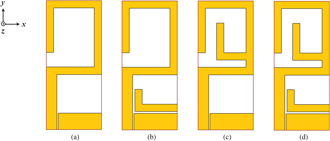
Fig. 2. Design evolution process. (a) Conventional ACS-fed meander-line antenna. (b) Conventional antenna with the first inverted-L-shaped resonator. (c) Conventional antenna with the second inverted-L-shaped resonator. (d) Proposed antenna with the two inverted-L-shaped resonators.

Fig. 3. Simulated reflection coefficient |S 11| of the proposed antenna with and without the two inverted-L-shaped resonators.
The performance of the antenna is affected by several key parameters. Figure 4 studies the parametric effects of the two inverted-L-shaped resonators. Parameters W 1 and L 2 are investigated to evaluate their impact on the antenna resonance frequencies. The effect of each parameter is shown with excluding the effect of the other ones. The effect of the parameter W 1 is shown in Fig. 4(a). From the shown figure, it can be seen that the 5 GHz-band can be generated and controlled by adjusting the width W 1 of the first resonator. As W 1 increases, the performance gets better, which is possibly due to increasing the coupling with the feed line. Optimal result is obtained for W 1 = 11.5 mm. Due to the indirect coupling with the antenna radiator, it can be observed that the first resonator has almost no effect on the conventional meander-line antenna resonant modes. A similar effect can be found for the length L 2 of the second resonator as shown in Fig. 4(b) in which the 4 GHz band is generated. With the increase of L 2, the capacitance between the second resonator and meandered radiator increases and the resonance frequency becomes smaller. Moreover, it shows that the second band of the conventional meander-line antenna shifts to lower frequencies with increasing L 2; while the first band is affected slightly by changing the length of L 2. This may be due to the current distribution of the antenna is changed by changing the current paths due to the direct coupling of the resonator with the antenna radiator. The simulated results obtained in Fig. 3 for the proposed antenna with and without the two inverted-L-shaped resonators indicate that the wide bandwidth from 4.1 to 5.95 GHz is mainly generated by the overlapping of the resonant frequencies of the two resonators.

Fig. 4. Simulated reflection coefficient |S 11| of the proposed antenna. (a) For various widths, W 1 of the first inverted-L-shaped resonator. (b) For various lengths, L 2 of the second inverted-L-shaped resonator.
In order to better understand the antenna behavior, the current distributions of the dual-band meander-line antenna at frequencies of 1.6 and 3 GHz are simulated and shown in Fig. 5(a). It can be clearly seen that the current is mainly distributes along the meandered radiator, and thus the resonant modes at 1.6 and 3 GHz are excited. Longer current path is observed for the lower resonant mode of 1.6 GHz. To investigate the tri-band operation mechanism, the simulated surface current distributions of the proposed antenna at the resonant frequencies 1.54, 2.45, 4.25, 5.1, and 5.8 GHz are depicted in Fig. 5(b). It can be seen that the surface current distributions at the resonant frequencies are different. At 1.54 GHz, the surface current distributions are mainly concentrated along the meander-line and the second inverted-L-shaped resonator consists of L 2 and W 2, which longing the current path and enables the proposed antenna to lower shift the first resonant frequency of the conventional meander-line antenna from 1.6 to 1.54 GHz. Similar effect can be found for the frequency of 2.45 GHz, in which the longer current path enables the antenna to lower shift the second resonant frequency from 3 to 2.45 GHz. In contrast, for the tri-band antenna, the average length of current path, which enables the antenna to resonate at the frequency band of 2.45 GHz, is shorter than that of the lower frequency band of 1.54 GHz as expected. This demonstrates that the meander-line and the second inverted-L-shaped resonator are the key radiating elements for the lower resonant modes. While at higher resonant modes, the frequency of 4.25 GHz is mainly generated by the second inverted-L-shaped resonator. Whereas the frequency of 5.8 GHz is generate due to the effect of the first inverted-L-shaped resonator consists of L 1 and W 1. For the middle frequency of 5.1 GHz, it can be clearly seen that the current is almost uniformly distribute along the meandered radiator and the two resonators.

Fig. 5. Simulated surface current distributions at different frequencies. (a) Conventional meander-line antenna, antenna #1 and (b) proposed antenna.
IV. RESULTS AND DISCUSSION
All simulations are performed using CST Microwave Studio (MWS), an industry-standard software simulator which is based on FIT (Finite Integration Technique) that is equivalent to FDTD (Finite Difference Time Domain) method [32]. To evaluate the performance of the proposed tri-band antenna, a prototype is fabricated and measured. The photograph of the proposed antenna is shown in Fig. 6(a). The reflection coefficient |S 11| of the tri-band antenna was measured by Agilent Vector Network Analyzer PNA-X N5242 with port impedance of 50-Ω. A comparison of simulated and measured reflection coefficients results is given in Fig. 6(b). Good agreement is achieved between the simulation results and the measured data. The slight discrepancy between the simulated and measured curves may be attributed to the errors of the manufactured antenna. It can be seen form Fig. 6(b) that the proposed antenna has three operating bands. The measured impedance bandwidths, which are defined by the reflection coefficient of −10 dB are 150 MHz (1.48–1.63 GHz, 9.61%) at the center frequency of 1.56 GHz, 230 MHz (2.25–2.48 GHz, 9.74%) at the center frequency of 2.36, and 1.78 GHz (4.22–6.0 GHz, 34.83%) at the center frequency of 5.11 GHz. These characteristics meet the required bandwidth specifications of 1.575 GHz GPS L1, 2.4 GHz WLAN, and 5 GHz HIPERLAN/2 applications.

Fig. 6. (a) Picture of the fabricated prototype. (b) Simulated and measured reflection coefficients |S 11| of the proposed antenna.
The simulated and measured co-polarization and cross-polarization normalized radiation patterns of the proposed antenna in both xz-plane (E-plane) and yz-plane (H-plane) at frequencies of 1.56, 2.36, and 5.8 GHz are illustrated in Fig. 7. The patterns in the xz-plane are nearly omnidirectional at all frequencies, and monopole-like patterns in the yz-plane plane are also obtained. The high-level cross-polarizations in the yz-plane are mainly due to the current distributions at the top of the meandered radiator, which are perpendicular to the direction of the main radiation current as shown in Fig. 5(b). The discrepancy between the simulated results and the measured ones is due to the connector existence and the edge diffraction from the antenna edges and some minor imperfections in the Anechoic Chamber (NSI near-field Anechoic Chamber system in this case). On the other hand, the asymmetry of the ground plane and its small size can cause the currents to flow back to the outer surface of the feeding cable (standard 50-Ω lossless cables in this case), resulting in some ripples, which appear clearly at 5.8 GHz, the higher resonant frequency. Regarding to the feeding cable effect on the measurement accuracy of the reflection coefficient |S 11|, it may results in some minor errors as touching or moving the cable (semi-flexible in this case), also |S 11| measurements are not done in Anechoic Chamber, so multipath and loading effects may have some effect. However, these errors will not be large enough to alter the general characteristics of the |S 11| behavior or the main resonance frequencies locations.

Fig. 7. Simulated and measured co- and cross-polarization normalized radiation patterns of the proposed antenna in both xz- and yz-planes at frequencies of (a) 1.56 GHz, (b) 2.36 GHz, and (c) 5.8 GHz.
The simulated realized gain and efficiency of the designed antenna is shown in Fig. 8. The antenna gains are about 0.8, 1.6, and 2.9 dBi for the 1.54, 2.45, and 5.4 GHz bands, respectively. The maximum gain observed is 3.4 dBi at the frequency of 5 GHz. The antenna efficiency is greater than 70% over the operating frequency range.

Fig. 8. Simulated realized gain (a) and efficiency (b) of the proposed antenna.
A detailed comparative study of the recently reported multi-band antennas in the referenced literature based on CPW- and ACS-feeding structures in terms of size, operating bands, impedance bandwidth, average peak gains and radiation efficiency are given in Tables 2 and 3, respectively. From Table 2, it can be seen that the antenna exhibits all the benefits of CPW-fed antenna along with the advantage of a more compact design. Significant miniaturization in size has been achieved in the proposed design regarding the operating frequencies estimated in term of free-space wave length, λ 0 at the first resonance frequency. In comparison with general CPW-fed antenna, an ACS-fed antenna structure consumed almost 50% area by considering only half of the ground plane of CPW-fed structure. Table 3 shows that most of the reported ACS-fed multi-band antennas were compact in size. However, none of the available designs can provide a multi operation includes lower frequency bands covering applications such as GPS L1 operates at 1.575 GHz. To overcome these problems, a compact 15 × 35 mm2 ACS-fed tri-band meander-line antenna is presented in this paper.
Table 2. Comparison of proposed antenna's size and performance with referenced CPW-fed multi-band antennas.

Table 3. Comparison of proposed antenna's size and performance with referenced ACS-fed multi-band antennas.

V. CONCLUSION
A simple and compact ACS-fed antenna has been designed using a meandered radiating structure and two inverted-L-shaped resonators. Parametric studies to show the effect of dimensions of the inverted-L-shaped resonators in the meandered radiating performance have been performed and discussed. The antenna can achieve three sufficient impedance bandwidths cover the 1.575 GPS L1, 2.4 GHz WLAN, and 5 GHz HIPERLAN/2 operating bands, with good radiation characteristics, reasonable gain, and high efficiency. Finally, it can be concluded that using the meandered structure and the ACS feeding scheme can provide miniaturization in printed antenna size compared with conventional CPW-fed antenna working in the same frequency bands, which has advantages of easy integration into printed circuit boards.
ACKNOWLEDGEMENT
This work is supported by King Abdul-Aziz City for Science and Technology (KACST) Technology Innovation Centre (TIC) in Radio frequency and Photonics (RFTONICS) for the e-society hosted by King Saud University (KSU).
 Ayman A.R. Saad was born in Qena, Egypt in September 11, 1983. He received the B.Sc., M.Sc., and Ph.D. degrees in Electrical Engineering from Minia University, Egypt in 2005, 2009, and 2013, respectively. He is currently the Managing Director of Kosseir Radio. He has 4 years of teaching experience in various reputed engineering colleges in Egypt. His main research interest includes small antennas and microwave circuits design for UWB and MMW applications.
 Ahmed A. Ibrahim was born in 1986. He received the B.Sc. degree, with grade of very good, in electrical engineering from the Electronic and Communication Engineering Department, Minia University, Elminia, Egypt in 2007. He was awarded the M.Sc. degree in Electronic and Communication Engineering from Elminia University in 2011 and the Ph.D. degree from Electronic and Communication Engineering Department, Minia University in 2014. He is now a post-doctoral fellow in the Otto-von-Guericke-Universität Magdeburg, Germany. He is also a lecturer in Electronic and Communication Engineering Department. His research focused on the design and analysis of microstrip antennas, microstrip filters, and its application in wireless communications; and also on metamaterial MIMO antenna and different metamaterial applications in microwave bands.
 Osama Haraz was born in Aswan, Egypt in October 23, 1976. He received the B.Sc. (with honors) and M.Sc. degrees in Electrical Engineering from Assiut University, Egypt, in 1999 and 2004, respectively and the Ph.D. degree from Concordia University, Montreal, QC, Canada, in 2011. From 1999 to 2000 he worked with Nuclear Material Authority, Cairo, Egypt as an Electronic Engineer. Between 2000 and 2006 he was with the Electrical Engineering Department of faculty of engineering, Assiut University as an assistant lecturer. He is currently a Researcher in the KACST Technology Innovation Center in Radiofrequency and Photonics for the e-Society (RFTONICS), King Saud University. He is also an Assistant Professor of Electrical Engineering (Electronics & Communication Section), Assiut University. His current research interests include small antennas, microwave circuits for UWB and MMW applications, phased array antennas, interaction of EM waves with new advanced materials. Dr. Haraz received the 2010 Concordia Ph.D. thesis completion award from Concordia University, Montreal, Canada. He has also received the Scholarship of the Egyptian Ministry of Higher Education (2006–2010), the 2000 MobiNil communication company excellence award, and the 6th October University Academic Distinction Award (1997–1998), Cairo, Egypt.
 Ayman Elboushi was born in Zagazig, Egypt, in 1978. He received the B.Sc. degree in Electrical Engineering from Zagazig University, Egypt, in 2000, M.Sc. degree from Ain Shams University, Cairo, Egypt, in 2007, and Ph.D. degree from Concordia University, Montreal, Canada, in 2014. From 2008 to 2014 he was working as a researcher in electromagnetic group, Concordia University. From 2014 till today he is working as an antenna group leader in RCSL Laboratory, PSATRI Institute, Riyadh, Saudi Arabia.


