


1. INTRODUCTION
In designing products, designers create artefacts that should be useful, efficient, safe, and provide a satisfying user experience. Shape and material are important means toward achieving these ends, as Fulton Suri and Marsh (Reference Fulton Suri and Marsh1997) put it: “While we cannot control people's subjective experience, we can adjust design expressions—the formal and behavioural qualities of design—to influence an experience appropriately.”
In the early stages of a design process, designers need to rapidly and frequently shift their attention between the abstract and the concrete, between experience and form, between perceived use and material properties. To support this cognitive activity, they make extensive use of external representations such as sketches and physical models. Schön (Reference Schön1992) describes this interaction as a conversation between the designer and the sketch, in which thoughts are externalized into sketches, and the sketches are reinterpreted into new thoughts. Sketches, that is, rapid, incomplete, and ambiguous externalizations, are recognized as key tools to support design thinking by individuals (Fish & Scrivener, Reference Fish and Scrivener1990), and groups (van der Lugt, Reference van der Lugt2005). Cardboard and foam models can be regarded as three-dimensional (3-D) sketches (Djajadiningrat et al., Reference Djajadiningrat, Gaver and Frens2000; Buxton, Reference Buxton2007), which appeal to the human perceptual and motor skills (Hummels, Reference Hummels2000), and support intuitive understanding of complex geometrical and physical relationships (Piper, 2000).
However, although the tools just mentioned support shape and dynamic behavior, they provide less help with explorations of surface qualities such as materials or printed graphics (for brevity, we will refer to both of these visual surface qualities by the term material). Most often, the materials are explored separately from shape, with the help of moodboards and material samples. Connecting shape and material is left implicit, up to the unaided imagination of the designer.
Modern computer-aided design (CAD) applications can be used to bridge the gap, producing high-quality images of both shape and surface, but such tools do not have the fluent interactions or expressive forms that are typical of sketching (Stappers et al., Reference Stappers, Keller and Hoeben2000; Do, Reference Do2002). CAD applications are aimed at the latter, detailing stages of the design process and their support for exploring material is limited.
The Skin tool was designed to overcome these two problems. It provides support for exploring materials (colors, patterns, and graphics) in the context of the product shape, and of exploring shape and material together. It does so by providing a “sketchy” interaction and aesthetics needed to support creative thinking in the early stages of design. Skin works by projecting computer-generated images onto a physical model, allowing its users to rapidly and intuitively manipulate both the model and the image.
In this paper we describe three studies in which Skin was evaluated in a product domain where the fit between shape and material is essential: ceramics. In each study, a real-world design problem was tackled by either a practitioner or advanced design students. We evaluated the resulting designs and the exploratory behavior of the designers to verify that the tool supported the conversational qualities defined by Schön and to study its viability as a tool for current-day practice.
2. APPLICATION DOMAIN
Although it is impossible to see shape without seeing material (Bailey, Reference Bailey1855), it is likewise impossible to see material without shape. In product design, material or color is not considered in isolation, but against the context of a product's shape. The choice of material cannot be separated from the choice of shape and manufacturing process. Ashby (Reference Ashby1999) developed a model to support material selection in mechanical engineering; Figure 1 depicts the relations involved. Ashby defines material as: “the matter from which things are made.” In this matter-centric definition all aspects of the product's embodiment are considered to be material. Shape is the external geometry of a product. To achieve the shape, the material is subjected to manufacturing processes, such as forging, casting, machining, and welding. The relations in the figure are two-way interactions: the choice of shape restricts the choice of material and manufacturing process; but equally, the choice of a manufacturing process limits the materials and shapes that can be used. The interactions between function, material, process, and shape are seen as the central problem of materials selection in mechanical design (Ashby, Reference Ashby1999). Tools that support designers in one of these aspects should therefore take into account the other aspects and their interactions as well.

Fig. 1. Ashby's model visualizes the interactions between shape, material, (manufacturing) processes, and function in mechanical engineering. When selecting a material all of the other aspects must be taken into account.
In product design, as opposed to mechanical design, the notion of function not only considers the technical working of the product, but also includes ergonomics and aesthetics. The importance of material in the expressive qualities of products has been stressed by many authors (e.g., Arnheim, Reference Arnheim1969; Jordan, Reference Jordan2000). Designers have various means to design expression or meaning into the physical product manifestation. An expressive quality as “transparency” might be achieved through an open shape made out of sheet metal, through a surface that contains a pattern with small holes like a mesh, or through a translucent material. Likewise, “restless” as a bodily expression, usually referring to people, might be expressed in the various aspects of the product, through imbalance of shape (van Rompay et al., Reference van Rompay, Hekkert, Saakes and Russo2005), through texture or maybe through a dynamic behavior of the product that expresses restlessness. Likewise, products that appear to be made of one material but are, in fact, made from another, can result in disappointment, when they are experienced as “fake” (Jordan, Reference Jordan2000), or might elicit a surprise through sensorial incongruities (Ludden et al., Reference Ludden, Schifferstein and Hekkert2008).
2.1. Design techniques for exploring and choosing material
Sketches mainly focus on conveying shape, although materials can be depicted. Most often materials are indicated in an abstract way, and their appearance is strongly influenced by the drawing style or the type of tools used. For instance, the appearance of materials in a watercolor drawing is greatly different from that in a sketch made with markers and fineliners. Properties as glossiness can be indicated by exaggerated highlights. But other patterns such as carbon fibers are difficult to draw by hand. For presentations, designers often mix hand drawings with photographs of texture patterns or use 3-D visualization software. Likewise, implicit notions of materials are articulated by depicting shape associations, utilizing typical features of a style or manufacturing process, such as bevels. Two techniques are often used in exploring expressive qualities in searches for materials: making moodboards and collecting samples.
2.1.1. Making moodboards
Moodboards, such as the example shown in Figure 2, function as a nonverbal way to express an abstract idea or a specific atmosphere. The act of making of a moodboard is a creativity technique that is used for two purposes: as a metaphorical expression (McDonagh et al., Reference McDonagh, Bruseberg and Haslam2002) and as a sensory expression (Muller, Reference Muller2001). In this study we use Muller's description: “Designers form new ideas while glancing through magazines and collections and intuitively selecting images and composing them together” (Muller, Reference Muller2001). This is what Keller et al. (Reference Keller, Hoeben and van der Helm2006) describe as: “to organize visual material and find new insights in the order that comes from that.” Moodboards make effective use of the richness of graphics expressions readily found in magazines.

Fig. 2. (Top) A collection of samples on a designers' desk. (Bottom) Two moodboards used for exploring product expression in a nonverbal way. [A color version of this figure can be viewed online at journals.cambridge.org/aie]
2.1.2. Collecting sample materials
Moodboards can provide visual or symbolic palettes of color and material, but do not serve the other senses, such as touch. To overcome this limitation, designers keep collections of inspiring materials, sample products, and technical solutions (Fig. 2). Sample products may be bought for inspiration in a specific project, or collected as a special interest of the designer. These collections are often personal and displayed in the designer's workspace (Pasman, Reference Pasman2003). Samples are valuable because they are “the real stuff” that can be felt, probed for strength, and also exhibit many visual aspects that cannot easily be drawn, such as dichromatic effects, foggy translucency, or reflection under dynamic light conditions. Searching through samples elicits new ideas in ways similar to making a moodboard. In the past years, various commercial libraries with large amounts of materials samples have become available. (e.g., Beylerian & Dent, Reference Beylerian and Dent2005).
Although browsing through inspirational materials can be considered as a conversational cycle in Schön's sense, one limitation is the designer's inability to manipulate aspects of materials. Combining a sample with a product shape in one's mind poses high demands on one's imaginative abilities. This is already very difficult for designers, and practically impossible for laymen involved in design decisions. Both laymen and experts have difficulties in predicting impact of a specific material or graphic on a product's shape.
2.2. Ceramic design
In this study, the design of glazed ceramic objects serves as an example for product design in general. In ceramics, material (glaze) and shape (clay) are explored separately, with distinct tools, and not until the final stages can the impact of a specific material on a specific shape be experienced as a whole.
Ceramics has a long tradition, dating back several millennia. It contains great craft-based industries like Wedgwood pottery, valued sometimes as highly as silverware (Ashby & Johnson, Reference Ashby and Johnson2002). Ceramic artists spend weeks modelling statues out of clay before they paint it with glaze, that is, white or dull-colored powders that are transformed by high temperatures into brilliant colors (Reijnders, Reference Reijnders2005). Depending on the ingredients used, the glaze may have to be fired multiple times at various temperatures. Once out of the kiln, the glaze finally shows its intended appearance and the end result can be observed for the first time. The outcome of ceramic artwork often looks completely different than it does during the various phases of the design process. Although various visualization techniques are used during the design process (e.g., artists make sample tiles to experiment with glazes), the moment of opening the kiln is described as “a magical moment,” as even the most experienced craftsmen cannot fully predict its outcome. Often there is no second chance or iteration.
3. TOOL DESIGN
In this section we describe a tangible design tool, Skin, that we developed to incorporate material manipulation in the early stage of designing, that is, the sketching phase. The aim of the tool is to unite on the one hand the qualities of samples and moodboards, using the richness of the world, and in contrast, the qualities of physical modeling. Skin uses the media capabilities of computers, allowing designers to experience the interactions between material and shape at an early stage. The tool is intended to fit in with, and be used in collaboration with, the current tools, not to replace them. Skin was developed from 2005 to 2008 in an iterative process in close collaboration with industrial partners.
3.1. Mixing the digital and the physical
The Skin tool builds on the efforts to explore the transition of virtual and physical media, with an emphasis on the opportunities of new media tools in techniques to support designers. For example, the InstantTemplates tool (Saakes & Keller, Reference Saakes and Keller2005) photographs hands interacting with a product and projects the photo on paper. Designers can use the projected image as a template to draw on. InstantTemplates was built as a tool to support sketching physical interactions by letting designers draw over projected photographs, similar to practice in traditional drawing classes where templates are commonly used as a background underneath the drawing paper. In a similar fashion, Cabinet (Keller et al., Reference Keller, Hoeben and van der Helm2006) is a tool for merging collections of digital and physical visual materials. It consists of a table interface on which digital images are spatially grouped; it thereby provides a nonverbal way of entry, search, and retrieval. Physical images can be added seamlessly to the cabinet's collection with a built-in digital camera.
Another example in this area is the I/O brush (Ryokai et al., Reference Ryokai, Marti and Ishii2004), a drawing tool for children to explore colors, textures, and movements found in everyday materials by picking them up and drawing with them on a digital canvas. The physical brush eliminates the need for a predefined digital palette. The I/O brush encourages children to explore their surroundings in the process of creating their drawings.
3.2. Spatial augmented reality
The key display technology in Skin is projecting computer-generated images onto physical models. Projected light has long been used in art practice to alter the appearance of physical objects. For instance, filmmaker Peter Greenaway uses projections as an integral part of his visual style and Naimark (in Low et al., Reference Low, Welch, Lastra and Fuchs2001) demonstrated the beauties of using projected graphics on surfaces. In the field of augmented reality several sophisticated systems make use of projected light. These systems are generally referred to as spatial augmented reality systems, as opposed to head-mounted displays. The general idea of spatial augmented reality systems is to alter the appearance of a physical object by illuminating it with images generated by a computer graphics application.
Raskar et al. (Reference Raskar, Welsh, Low and Bandyopadhyay2001) demonstrated the use of physical objects as a canvas for 3-D computer graphics with the Shaderlamps system. His system tracks the position and orientation of physical objects, and a projector projects a shaded virtual 3-D copy on the objects. With a similarly tracked brush, the objects can be colored and annotated with virtual paint.
Various augmented reality systems have been proposed as design support tools for industrial and architectural design applications (e.g., Low et al., Reference Low, Welch, Lastra and Fuchs2001; Verlinden et al., Reference Verlinden, de Smit, Peeters and van Gelderen2003; Binder et al., Reference Binder, De Michelis, Gervautz, Jacucci, Matkovic, Psik and Wagner2004). All these applications show the advantages and feasibility of using augmented reality, but are aimed at the later, detailing, stages of the design process. Moreover few of them have been applied and integrated in the complexities of design practice.
3.2.1. Technological issues regarding spatial augmented reality
Skin makes use of “straightforward” projection of 2-D images over 3-D objects, ignoring a number of issues in photorealistic presentation that would make the technology very complex. Projecting virtual images on nonplanar surfaces involves advanced technology and calibration:
• If the physical model should display differently colored parts, the computer application must have an internal representation of the shape. That model representation can be as simple as an area in the projected image; however, the projector and the illuminated object need to be aligned precisely to use the object as a canvas.
• Projectors project the virtual imagery from a single point, and therefore illuminate the object from one side only. Concave objects can occlude themselves, requiring multiple projectors to light the objects from multiple sides (Raskar et al., Reference Raskar, Welsh, Low and Bandyopadhyay2001).
• When the object moves or has moving parts, the position and orientation has to be tracked to adjust the projection accordingly. Tracking introduces a new set of technological issues of resolution, update rate, and lag. One elegant solution is to limit the degrees of freedom, for instance, with a turntable (Verlinden et al., Reference Verlinden, de Smit, Peeters and van Gelderen2003). In Piper's (2002) Illuminated Clay, an augmented table for landscape analysis, the object itself is dynamic. Because of the specific nature of landscapes, surfaces with modest height variations and no undercuts, Piper uses a 3-D scanner that captures the clay surface into a height map for matching the virtual representation with the physical surface.
• When projecting on curved surfaces or surfaces that are not perpendicular to the direction of projecting, the image deforms over the surface. Compensating for these distortions requires incorporating a virtual model. The projector is then used as a “reverse camera” through which the virtual 3-D model is projected, and the field of view, position, and orientation of the projector in respect to the physical object is matched.
• Some visual effects, such as reflections on glossy surfaces, depend on the observer's viewpoint. To achieve view-dependent color, not only the position and orientation of the object but also the position and orientation of the observer(s) must be taken into account.
• For the object to appear to be in the environment, the lighting and reflections of the virtual object must match the environment. Debevec (Reference Debevec1998) introduced a technique to record and apply environmental light conditions. In the texture brush project (Binder et al., Reference Binder, De Michelis, Gervautz, Jacucci, Matkovic, Psik and Wagner2004) a second projector projects a virtual world enabling illuminated objects to be appropriately illuminated.
Most augmented reality systems pursue photorealism in image generation. This makes their setups quite complex. Moreover, most of these systems (e.g., Piper, Reference Piper2002; Verlinden et al., Reference Verlinden, de Smit, Peeters and van Gelderen2003; Binder et al., Reference Binder, De Michelis, Gervautz, Jacucci, Matkovic, Psik and Wagner2004) rely on a traditional screen-based interface for the functionality of the tool. Typically, a demarcated projection area next to the model is dedicated to visualize controls, manipulated through a traditional mouse or similar input device. As a result, these systems can produce compelling visual presentations but do not support the interactivity, speed, and fluency necessary to support early ideation in the way that sketching does.
3.3. Design of Skin
Skin, as shown in Figure 3, was designed especially to allow that sketching type of interaction. Its objective differs from those of the systems just mentioned in that it focuses in the early stage of product design. We utilized the unique aspects of this stage, that is, roughness and ambiguity inherent in sketching, and apply that in the way the imagery is created, the way the imagery is projected, and the direct, physical way images and model can be manipulated. Elsewhere, we have given a detailed description of the system (Saakes, Reference Saakes2006) and its use in packaging design (Saakes & van der Lugt, Reference Saakes and Van der Lugt2007). In this section we summarize its key properties as related to 3-D product design and tangible interaction.

Fig. 3. The Skin setup consists of an object table, on which objects are illuminated with computer generated light, and a material palette for browsing and mixing visual materials. Physical materials are captured in real time with a video camera. Skin is designed to support small groups of designers in exploring and generating product concepts. [A color version of this figure can be viewed online at journals.cambridge.org/aie]
Skin projects materials as flat 2-D images without any tracking or knowledge of the 3-D object, thereby any object can be used as long as it sufficiently reflects colored light. Objects themselves can be manipulated, moved, turned, or deformed. The projection then deforms on the object, and during manipulations of the object, its appearance will change. For photorealistic presentations of details this would be a problem, but in early sketching these imprecisions and distortions are a positive quality. The rough and ambiguous projection that occurs when moving the objects in the projected light and seeing patterns and graphics deform on the physical objects will result in deliberate and accidental indeterminacies, leading to serendipitous discoveries (Keller et al., Reference Keller, Hoeben and van der Helm2006) of unexpected new combinations.
3.3.1. The object table
Skin's hardware consists of a projector mounted under the so-called “object table.” By means of a mirror, imagery is projected horizontally along the surface of a table, so that only the objects are illuminated, not the table itself (see Fig. 4). The objects on the object table catch the light from the projector. A wall behind the object would show unfocussed and distractive projections, which disrupt the visual compellingness of the object, and should be masked. Various methods exist to mask the surplus light: in software, by using nonreflective black felt backgrounds, or making sure no background elements are present to catch the light. When developing the horizontal projection setup, we found a fourth way: a stronger light source behind the object such as the natural light from a window naturally washes out the surplus light. This eliminates the need for masking techniques in software, which again would require tracking or extensive calibration. Moreover, the system is intended for normal conditions of practice, and daylight is generally available in a design studio.

Fig. 4. The object table consists of a projector mounted beneath the table, and it projects computer generated light, through a mirror, on objects on the table. The surplus light around the objects is masked with a second light source, for instance, the light from an outside window, which washes out the light generated by the projector. [A color version of this figure can be viewed online at journals.cambridge.org/aie]
3.3.2. The material palette
The image generation of Skin is called the “material palette,” and makes use of existing images that can be manipulated to some extent. Making use of existing imagery and the richness found in the world lets Skin blend in with the traditional techniques of using collections of magazines and samples. Reusing such imagery is an efficient way to quickly create patterns and textures that blends in well with the designer's process.
At first, we solely used digital images from the designer's collections, both graphics as patterns. A paddle controller lets users browse through the collection and provides the ability to scale the projected images. Source images are always tiled and fill up the display image. When we evaluated Skin for application in packaging design, users showed a need for capturing and adding physical materials, which they often had ready at hand (Saakes & van der Lugt, Reference Saakes and Van der Lugt2007). Therefore, Skin 2.0 contains, similar to I/O brush (Ryokai et al., Reference Ryokai, Marti and Ishii2004), a video camera to capture new source material, such as graphics found in magazines or fabrics. Materials are captured with a 30 frames per second video feed, mixed in real time with the images from the digital collection using a chroma-key technique, and scaled and tiled with a second controller before they are projected over the objects. See Figure 5 for Skin's system overview.

Fig. 5. In Skin (1) the digital images are browsed and scaled with a paddle controller. (2) Physical materials are manipulated under a camera and scaled and tiled with a second paddle controller. (3) The color black is made transparent, and the captured physical images are superimposed over the digital materials. (4) The combined image is projected on the model. The model can be moved and oriented freely on the table in order to explore the interactions of shape and material. [A color version of this figure can be viewed online at journals.cambridge.org/aie]
A limitation of Skin is that objects can only be flood filled with a single material. With the camera, a crude way of local graphic manipulation is added. As shown in Figure 6, users can compose graphics consisting of multiple elements, and mix them with digital imagery.

Fig. 6. Examples of “skinned” objects. (Left) An object with a digital pattern. (Center) A physical material and the object skinned with both the digital pattern and the physical material. Notice the deformation in the circle patterns. (Right) Two examples of object manipulation that alter the location and orientation of the projected pattern. [A color version of this figure can be viewed online at journals.cambridge.org/aie]
3.3.3. Capturing designs
Concepts created on Skin are photographed with a digital camera, and can so be retained for the latter stages of the design process and will focus, for instance, on the CAD modeling phase.
4. CASES IN CERAMIC DESIGN
To study the anticipated benefits of the tool we took an action research approach: embedding the new technique in existing practice and carefully observing and reflecting on its impacts (Avison et al., Reference Avison, Francis, Myers and Nielsen1999). We chose this approach because we wanted to do justice to the inherent complexity of the idea generating processes in design practice. Controlled research methods often have to make many concessions, such as a laboratory setting, a simplified abstract task, or using inexperienced students instead of designers. The studies served not only to test the technique but also to further evolve it (Fischer, Reference Fischer2002).
4.1. Ceramics as an example of design practice
We conducted three case studies where designers worked with Skin in typical design situations. These cases were all drawn from the field of ceramics design, because (as argued above) this explicitly shows the separation of shape and material in the design process. The cases were chosen so as to vary widely in several dimensions: the complexity of the tool setup (from plain projection of computer images to a turnkey dedicated tool), the expertise levels of the designers (from expert artists to salesmen working with clients), and the style of the idea generation process (individual exploration, teamwork, negotiation). These different situations allowed us to obtain different perspectives on the versatility of the tool and the demands made on it in situations of use.
The first case featured artists working individually on large statues. The difference with product design is that the statues are large and one of a kind: various design decisions are made while sculpting the final artwork. The second case describes a team of design students designing a new line of earthenware; here, both shape and glaze are manipulated. The third case focused on meetings with customers and salesmen in the design of custom-made Delftware. Here the focus is on the graphics of the glaze.
4.2. Design, intervention, and reflection
In each case, we first demonstrated the Skin technique to the designers. Then we adjusted the design of the tool to contextualize it for their specific application. After that, they used the tool in their otherwise regular work process, and we observed and recorded the session on video. After the session, together with the participants, we reflected on the benefits of the tool.
4.3. Case 1: The expert artist exploring individually
In a half-day session we observed two ceramic artists (H.v.B. and P.v.d.N.) working with Skin. The participants had many years of experience in designing ceramics and were in the process of modeling large statues. Both were frequent and experienced computer users, and used 3-D modeling and digital painting tools to visualize and design their work. The session was hosted at Atelier Struktuur68, a studio in The Hague that facilitates large-scale ceramic projects.
4.3.1. Method
We planned and prepared two techniques to apply color to the statues, as depicted in Figure 7. The first consisted of browsing and scaling digital patterns for projection on the statue. The second technique consisted of painting on the statue by means of a pen tablet and off the shelf painting software. This second technique was requested by one of the artists because it allowed local application of color. His statue was figurative and consisted of multiple parts, each intended to receive a different color. Prior to the workshop we asked the artists to send us the visual materials they wanted to use during the workshop. On request of one of the artists, we also added a collection of marble and stone patterns. This collection resembled the patterns in the library of his visualization software. During the session the artists showed us several ceramic tiles containing experiments with patterns of splattered glaze, which we photographed and added to the collection.

Fig. 7. (Top) A large sculpture in the shape of a Roman helmet for the Dutch embassy in South Africa, skinned with a projected marble pattern. (Top right) P.v.d.N. and H.v.B. holding the paddle controller. (Bottom) P.v.d.N. (standing) and H.v.B. (sitting) and the statues: “afterwar delight” colored with an off-the-shelf painting tool using the statue as a canvas. [A color version of this figure can be viewed online at journals.cambridge.org/aie]
4.3.2. Prototype
The projector had a brightness of 3000 ANSI lumens and a 500:1 contrast ratio. This was sufficient to light up the grayish clay statues with vivid and saturated colors under daylight conditions in the workshop.
We provided a paddle controller to browse through the collection. Pressing its button advanced to the next pattern; rotating the button scaled and automatically tiled the patterns.
The paddle controller was attached to a long cable so the artists could walk freely around their statues and still browse the projected artwork.
For the painting technique we provided a Wacom pen tablet. Brushes and colors were selected using the laptop screen and the statue was directly used as the canvas.
4.3.3. Observations
From the first moment the artists were amazed by the magical effect of seeing their statues in real scale flooded with colors: “Wow! This really does something to me” [H.v.B.], “this immediately gives a classical feel” [P.v.d.N.] commenting on a marble texture on his statue. “I like the way the stones are colored here” [P.v.d.N.] pointing at a specific area of his statue.
Projecting colors and patterns on the clay radically changed their ideas and made them experiment with new mixes of glaze that they had not previously used on ceramics. Patterns of dark purple marble with white veins brought up discussions on how to recreate the effect in glaze. Enlarging and thereby exaggerating marble patterns triggered a range of new experiments, of painting marble patterns. Tiled patterns seem to have specific scales on which they interact, and therefore, the shape and details shape and were favored.
We expected the artists to talk about technical issues of our tool. However, its properties, such as deformation of the patterns on their statues, or the shadows caused by occlusion were not a topic. The artists started a lively discussion about the statues and the expressive effects. Often they walked up to the statue to show specific areas to each other, for instance, how a particular curve lines up with the projection. They seemed to focus on detailed areas of their statues, and it seemed that getting the whole visualization right seemed to be of lesser importance.
4.3.4. Discussion
Although both artists had made several visualizations before the session, experiencing their statues in full color on real scale did change their view on glaze, and opened up previously unconsidered ways of painting. We found confirmation that using projected imagery put forward new ideas that could not have been easily encountered by exploring glazes or shapes apart from each other. The tangible approach invited a lively discussion about the designs. Moreover, these artists were experienced both in ceramics and in working with computer tools. In our opinion, the fact that they were amazed by the effect of working with the technically primitive tool is a strong indication of the innovative value of using such interactive tangible techniques.
4.4. Case 2: A design team exploring together
In a half-day workshop a design team generated a large number of ideas and design concepts. The design team consisted of three students with a bachelor's degree in industrial design engineering who were currently enrolled in the design for interaction master's program. The three worked in an internship at the Royal Delft Delftware factory to design a new collection of Delftware that would appeal to a younger generation of customers. The workshop was hosted in our lab, which is practically next door to the factory.
4.4.1. Method
Prior to the workshop, the designers had made sketches and collected visual materials. These materials were used during the session. They had bought a large variety of white earthenware products on which to project the graphics. All concepts were made within the constraints of Delftware (blue graphics on white ceramic objects) and the session focused on aspects of composition, decoration, and figurative art.
4.4.2. Prototype
In this workshop we used the Skin setup as shown in Figure 6.
4.4.3. Observations
The team enthusiastically talked and commented on their artwork visualized onto the tableware models. “This design is typically from department store x.” Often they found a nice graphic on one object and then tried it on various other objects.
Some of the concept designs could be traced back and directly attributed to the use of the Skin projection technique. When the students projected a traditional tile pattern, and moved a ceramic bowl through the beam of light, the pattern became partly visible and deformed over the curved surface, as shown in Figure 8. This effect gave rise to various explorations of traditional Delft blue graphics projected in unconventional ways on the objects.

Fig. 8. The design team working with Skin. (Top right) A photo of an augmented bowl, and (bottom) the glazed end result. (Bottom left) Contact sheets with photographs of the concepts they created during the workshop. The designs were painted and fired directly from these contact sheets. [A color version of this figure can be viewed online at journals.cambridge.org/aie]
4.4.4. Discussion
During the workshop the design team generated many concept designs and took many pictures to keep the ideas alive for later stages. Here we clearly found that manipulations in graphics inspired manipulations in shape, for example, changing the objects.
To our surprise, the team created glazed ceramic objects immediately following the workshop, without any further iteration, visualization, or evaluation of the concepts. They had printed their concept designs at thumbnail size, similar to a contact sheet for photos, and used that as a quick reference while painting the glaze. It seemed that during the workshop they had not only explored and generated designs, but they also had evaluated designs to a sufficient degree to move straight into producing earthenware prototypes, indicating that the ideas and visualizations during the workshop had matured significantly. Exploring colors and patterns on the physical objects had put forward new designs that were unlikely to have been discovered in separated stages of shape and graphic design.
4.5. Case 3: Bluebrush supporting salesman/client negotiation
The final case also took place at Royal Delft in a period of 6 months, and involved the development of various prototypes, interaction designs, and user studies. The aim of the study was to explore the benefits of new media tools in Royal Delft's design process. The study resulted in a dedicated tool, which is currently in use at the factory.
Royal Delft is the last remaining factory from the 17th century that produces ceramic pottery by hand and decorates these with distinctive hand painted blue decorations. It takes decades to acquire the skills of a master painter who is allowed to design new decorations on the products. Prior to our intervention, Royal Delft had no experience using computer tools in their design process.
At first we targeted the technique at the painters. Although they appreciated the technique, and could imagine its use for artistic projects, they could not relate it to their daily practice. When studying the design process at the factory we discovered that what we considered to be “designing,” that is, determining artwork and composition, happened at an earlier stage in the sales meetings. The decoration on tailor-made plates follows a strict traditional format, usually consisting of a border, artwork such as an image and a company logo, and a few lines of text. As shown in Figure 9, the design and layout of a plate are discussed in a meeting of the client and a salesperson, which results in a verbal description. Then, a painter draws the design with pencil on a plate and a photo of this sketch is returned to the client for approval. Oftentimes several iterations are needed before the client is satisfied and the design is finalized in glaze.
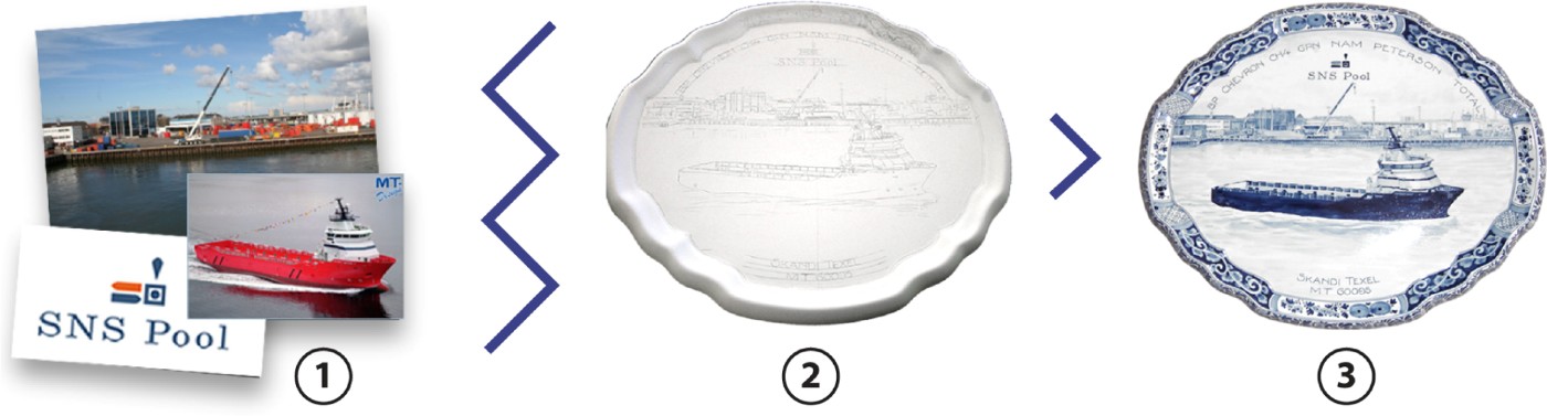
Fig. 9. (1) In the design of tailor-made Delft blue earthenware the layout and artwork is discussed in a meeting. (2) Then, based on a verbal description, a painter draws the design on a plate. (3) Several iterations between these two steps are often necessary before the design is finalized and glazed. [A color version of this figure can be viewed online at journals.cambridge.org/aie]
For Royal Delft, we developed a tool that provides an interactive visualization of artwork on the physical ceramic objects during the client meetings. We designed a dedicated physical interface, called Bluebrush, with which the various design options could be manipulated.
4.5.1. Prototype
In our earlier packaging study, and in the two cases described above, the interface consisted of controllers for scaling and browsing. All other functionality could be achieved by physically manipulating either the artwork or the model. The design of Delft blue plates and tiles is more specific and complex. Bluebrush therefore contains image generation software that consists of five layers that can be loaded with computer-generated digital images, text, and live video input. A pixel filter transforms the composed image to the “Delft blue painting style” to convey a rough impression of the painted end result. The image thus created is projected on to a physical plate placed upright on the table.
Bluebrush exposes its functionality in a physical panel as shown in Figure 10. The left side of the panel consists of five slots, representing five layers. Layers can be selected by pressing on a slot. Each layer can be loaded with artwork through a physical token. Bluebrush has tokens for digital images from a USB flashdrive, images from a network folder, snapshots taken with an attached webcam, round text, and lines of text. By inserting a token into a slot, the layer is loaded with the corresponding media and can be manipulated with the controls on the right of the panel. The controls consist of a dial for scaling, a joystick for positioning, and a next/previous button to browse through the images that are on a network folder or on the USB flashdrive.
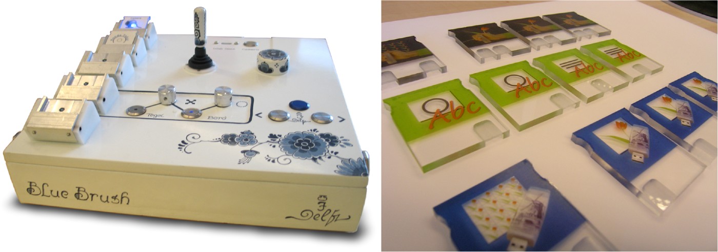
Fig. 10. The Bluebrush panel consists of a tangible, dedicated interface for designing Delft blue earthenware. The left side of the panel houses slots for media, and the right side of the panel houses various controls to manipulate the media. Media are loaded into a layer by inserting a token (right) into the corresponding slot. There are tokens for the various media types: images captured with a webcam, texts, and collections of images, for instance, from a USB flashdrive. [A color version of this figure can be viewed online at journals.cambridge.org/aie]
One layer is graphically distinguished and represents the border of a plate (if the object is not a plate but a square tile, this layer controls ornaments in the four corners of the tile). The media in that layer are mapped along the border of the plate (or in the corners). The five layers were found to be sufficient for most of the tailor-made objects.
A tangible approach of exposing the functionality was favored over a screen-based interface for a few reasons:
• A screen-based interface would focus the attention away from the object.
• The salespeople were not comfortable with using computers during the sales process.
• The interface makes the possible choices explicit (unlike regular computer interfaces, which remain obscure for the onlooker).
• The dedicated controls would invite the client to take over control.
4.5.2. Method
In two salesman/client meetings, Bluebrush was used to project computer-generated Delftware decorations on a white, unfinished ceramic plate, visualizing the various options that were under discussion. A TU Delft researcher was present in the background to assist the salespeople.
4.5.3. Observations
Both the clients and salespersons highly appreciated the tool. It helped the salespersons to show what is possible and the clients to express their wishes. Clients commented with remarks as “This edge goes very well with the portrayal” and “The stylized edge fits the modern style of the picture very well.” We also observed how clients influenced the composition of elements by indicating the size or position of images. Salespersons confirmed that such interactions with their clients did not occur in their regular practice.
Sometimes edges of artwork did not line up on the plates. When happened then was that the salesperson emphasized the skill of the painters: “The painters will do that right, try to ignore it for now.”
We observed that the clients were getting deeper involved in the design process and in a sense became co-designers of their products. The iterations that seem to be necessary for clients, to discover what they want and to see what is possible, now took place during a single meeting.
When the design was finalized, a digital photograph was taken, and it served as a visual contract. After the Bluebrush session, the painter painted the plate by hand, based on the artwork used and the composition as sketched with Bluebrush.
4.5.4. Discussion
We think that there are two problems in the current process of generating custom-made designs: first, the representation of the decorations, by means of a pencil drawing, is a bad predictor for the painted end result. Second, designs always contain compromises, and a few iterations are inevitable for the client to agree with a solution. These iterations are currently costly in both time and labor and might suffer from discrepancies caused by the verbal instructions given to the painter.
The visual design brief, consisting of a photo, taken during the meetings needed no further iteration (see Fig. 11). Thereby, the amount of the labor intensive iterations at later stages was reduced. Projecting on physical objects also helped to keep the discussion focused on the design and not on the tool or computer technology that generated the visualizations.

Fig. 11. With Bluebrush the various design decisions are now (1) visualized during the meeting and projected onto a physical plate. (2) A photograph of the augmented plate serves as a design assignment for the painter, who will transform the “sketch” into (3) a typical Delft blue style plate. [A color version of this figure can be viewed online at journals.cambridge.org/aie]
A limitation in the current design, as indicated by the salespeople, is the inability to “freeze” designs in order to review and compare them.
In 2008 a version of the Bluebrush was in permanent use at the sales department, and the first products designed with the Bluebrush were sold. The main use of the Bluebrush is to quickly create visualizations for requests that are handled by email.
5. DISCUSSION
The cases demonstrate the advantages of techniques that merge the synchronous exploration of shape and material. By bringing both explorations into a single activity, designers can iterate on each aspect quickly, and also alternate between conversational cycles of shape or material exploration. In the domain of ceramics these considerations have not been merged previously.
The cases indicate the opportunity to create a new design phase, bridging those of sketching and moodboard making on the one hand, and of CAD and physical modeling on the other. In this phase, designers can more fully make use of the potential of colors, graphics, and materials. We think this opens a new way to improve the quality of design, because iterations with long time delays are often omitted under the pressures real-world practice. The results indicate that such a phase should have the interaction qualities of sketching: quick and rough exploring, rather than to strive for accuracy of visualization, which is more typical of the later stages and most current CAD applications.
Our experience in these cases suggest that such a proposed explorative phase could result in a widening of the solution space, in which more concepts are considered. In the session with the design team, the parallel exploration of shape and graphics led to many new concepts, whereas in the first case study it allowed the designers to discover new ways of painting on their statues because they could experience their designs in color on a 1:1 scale. It is unlikely that these insights would have occurred if the designers used either moodboards or modeling separately.
Utilizing tangible interaction, both in the creation of imagery and in projecting on physical models made the interaction intuitive for the users, and created a shared platform in which they can jointly use the clearly exposed functionality.
5.1. Future work
Now that the advantages and potential benefits of using a sketchy augmented reality technique have been demonstrated in practice, the next steps will be to look deeper into the design process of Skin itself and to see how the use of Skin will influence design over time. Currently we are engaged in a longitudinal study to study how the successor to the Bluebrush interface (see Fig. 11) has been used by the sales staff at Royal Delft in the year following the case study.
ACKNOWLEDGMENTS
The authors thank Bart van den Berg for his design work in the Royal Delft case; Hans van Bentem and Pepijn van den Nieuwendijk for their input and allowing the results of the workshop to be included in this work; and Walter Aprile, Bart van den Berg, Aernout Peeters, and Joanna Boothman for their photos. We thank the anonymous reviewers for their suggestions for improving this paper.
Daniel Saakes is an Assistant Professor at Delft University of Technology, where he teaches courses on computer visualization and interactive prototyping with electronics. He is an industrial designer interested in products that cross the physical and digital domain. For his PhD he developed the Skin technique that he applied in several industries. He has also worked in the toy industry and as an experienced designer for virtual reality applications.
Pieter Jan Stappers is a Professor at Delft University of Technology, where he teaches design techniques and industrial design engineering. He acquired an MS degree in experimental physics at Radboud University Nijmegen in 1984 and completed a PhD at Delft University of Technology in 1992, using virtual reality simulator techniques in perception research. Since that time, Dr. Stappers’ research interests have shifted from virtual reality to new media tools for supporting design, with a focus on studying creative processes of designers and developing interactive tools for the support of creative design. After 2000, the scope of this research widened to include explorative contextual studies of user experience to develop tools and techniques for informing product/service designers about the needs and values of future user groups.


