I. INTRODUCTION
Owing to their ability to combat multipath fading and to deliver higher data rates; multiple-input and multiple-output (MIMO) systems become a well-known technique to enhance the performance of wireless communication systems [Reference Vaughan and Andersen1]. However; in a MIMO system, it is necessary to use several transmitter and receiver antennas at each end of the radio link, the signals received should be uncorrelated to achieve a high capacity [Reference Karaboikis, Soras, Tsachtsiris and Makios2–Reference Wallace, Jensen, Swindlehurst and Jeffs6]. These antennas must be capable of receiving signals independently, even they are closely spaced.
However, it is usually difficult to implement multiple antennas within small communication devices such as mobiles handsets. That latter happened to increase the mutual coupling and results high correlation coefficients. A good isolation between antennas and a good radiation patterns are required to obtain a better MIMO channel capacity.
Owing to its high performance, the planar inverted-F antenna (PIFA) is used as internal antenna for mobile communication devices. Some techniques must be applied to increase the isolation between the antenna elements, such as using a defected ground plane [Reference Meshram, Animeh, Pimpale and Nikolova7], inserting a small ground plane between PIFA and the mobile circuit board [Reference Gao, Chen, Ying and Parini8, Reference Gao, Chiau, Chen and Parini9] and maintaining the distance between antenna elements, as the critical parameter affecting the mutual coupling, at least equal to a half wavelength [Reference Gao, Chen, Ying and Parini8–Reference Balanis10]. Thus, other techniques to make PIFA broadband such as inserting slots [Reference Shagar and Wahidabanu11] and a parasitic element [Reference Ibnyaich, Ghammaz and Hassani12] can be applied. Otherwise, these techniques as well as the use of capacitive load [Reference Sanz-Izquierdo, Batchelor and Langley13] and shaped strip [Reference Tseng and Chen14] are used to achieve multiband performance [Reference Ben Ahmed, Bouhorma, Elouaai and Mamouni15–Reference Nepa, Manara, Serra and Nenna17].
A broadband dual-element PIFA antenna array for MIMO application is proposed. To increase the isolation between the PIFAs, a small ground plane and a parasitic element are placed between the radiating plate and the PCB. They are used also to widen the bandwidth. The antenna operates at the HIgh PERformance radio Local Area Network/2 (HiperLAN/2) (5.15–5.35 GHz, 5.47–5.725 GHz), the Wireless Local Area Network (WLAN) (5.15–5.35 GHz, 5.725–5.825 GHz), and the Worldwide Interoperability for Microwave Access (WiMAX) (5.25–5.85 GHz) frequency bands. Parametric investigation of the antenna is carried out to analyze the effect of the shape parameters on the operating frequency, the return loss as well as the isolation between the two PIFAs. The diversity characteristics and MIMO performance are evaluated in terms of envelope correlation coefficient (ECC) and diversity gain. The antenna characteristics are evaluated in both simulation and measurement.
II. ANTENNA DESING
Figure 1 shows the geometry of the proposed MIMO antenna array. The symmetrical back to back antenna elements are referred to Antenna1 and Antenna2. They are placed 2.7 mm from top and 3 mm from side on the system circuit board (PCB) with a separation of 40 mm (more than half wavelength λ = 53.95 mm, 40 mm = 0.74λ). An FR4 substrate of size of 100 × 60 × 0.8 mm3 is used as a PCB (ε r = 4.4 and tan δ = 0.018), on which the system ground plane of size 100 × 60 mm2 is printed below.

Fig. 1. Configuration of the proposed antenna: (a) 3D view and (b) top view.
Figure 2 shows the details of the PIFA antenna element. The dimensions of the PIFA element are WS = 5 mm, LT = 10.5 mm, and T = 0.3 mm. And the high of the antenna (H) is equal to 4 mm as shown in Table 1.
Fig. 2. View of the single antenna element of the proposed MIMO antenna: (a) profile view, (b) 3D view, (c) front view, and (d) top view.
Table 1. Optimized values of antenna array parameters.

The technique of locating a small ground plane between the PIFA and PCB [Reference Gao, Chen, Ying and Parini8, Reference Gao, Chiau, Chen and Parini9] is used in this study. It was made by collecting a rectangular plate with dimensions of WG = 7 mm, LG = 12 mm, and T = 0.3 mm, to a parasitic element (WG = 7 mm, HPE = 2.7 mm, and T = 0.3 mm). The small ground plane (rectangular plate) between the PIFA and the FR4 substrate with a gap of 1.2 mm is used to maintain good isolation between the antenna elements. Also it completes the part of the parasitic element which consists on widen the bandwidth, minimizing the reflection losses and providing the fine tuning to cover the entire band of operation. Plus to maintaining the high isolation, the small ground plane contributes on the width of the bandwidth to cover properly HiperLAN/2, WLAN, and WiMAX frequency bands.
The thickness of the copper sheet is 0.3 mm. The antenna is fed by the 50 ohm RG402/U (1673A) coaxial cable (d = 0.912 mm, D = 2.95 mm, and epsilon = 2.1).
III. RESULTS AND DISCUSSION
A) The S-parameters
A prototype of the proposed antenna, as shown in Fig. 3, was fabricated in the Electronics and Telecommunications Institute of Rennes (IETR), Ecole Polytechnique of the University of Nantes, France. A ZVA24R&S vector network analyzer was used to measure the S-parameters.
Fig. 3. The prototype of the proposed MIMO system.
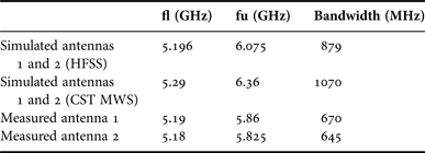
The S-parameters were measured and compared to the simulation results in Fig. 4. The simulations are performed originally in Ansoft's High Frequency Structure Simulator (Ansoft HFSSTM v.11), which is based on the finite-element method. The S-parameters simulated using CST MWS will be used to evaluate the diversity performance in section E. The simulated return losses of both PIFAs are identical due to the symmetric configuration. The measured return loss of Antenna 1 is slightly different from that of Antenna 2. This is due to the imperfection in the fabrication of two PIFAs. The measured resonant frequency of Antenna 1 is at 5.485 GHz, which is 0.075 GHz lower than the simulated one (5.56 GHz). The measured resonant frequency of Antenna 2 is at 5.51 GHz, which is 0.05 GHz lower than the simulated one (5.56 GHz). The measured bandwidths at −10 dB of Antenna 1 and 2, as shown in Table 2, span more than 644 MHz (narrower than the simulated one (879 MHz)), where the lower resonant frequency is 5.18 GHz (less than the simulated one (5.19 GHz)) and the upper resonant frequency is more than 5.825 GHz (less than the simulated one (6.07 GHz)). These bandwidths have covered the band of WLAN (5.2 GHz/5.8 GHz), WiMAX (5.5 GHz) as well as HiperLAN/2 (5.2 GHz/5.6 GHz).
Fig. 4. Measured and simulated S-parameters of the MIMO antenna array.
Table 2. Measured and simulated lower, upper frequency, and bandwidth at −10 dB for Antennas 1 and 2.
It is also shown in Fig. 4 where a high isolation better than 16.45 dB in simulation and better than 26 dB can be achieved in measurement. This is due to the space between the PIFAs that is more than the half wavelength (0.74λ) as well as the use of the small ground plane between the PIFA and the FR4 substrate.
Both simulated and measured results confirm the broadband performance of the antenna, its low return loss, the high isolation between its elements.
For comparison, a dual-element conventional PIFA with same height (H), width (WS), same location and same size of PCB as those of the broadband MIMO system was investigated. The length is 8 mm greater than that of the proposed MIMO antenna to achieve an operation in the 5 GHz band. The small ground plane and the parasitic element are removed from the model and the PCB acts as the ground plane. The S-parameters of the conventional PIFA array are shown in Figure 5.
Fig. 5. Simulated S-parameters of the conventional PIFA array and the proposed MIMO antenna array.
At −10 dB, the bandwidth is equal to 580 MHz, which is 90 MHz narrower than the measured bandwidth (670 MHz) and 299 MHz narrower than the simulated one (879 MHz). The antenna covers just the WLAN frequency band (5.725–5.825 GHz). HiperLAN/2 (5.15–5.35 GHz, 5.47–5.725 GHz), WLAN (5.15–5.35 GHz), and WiMAX (5.25–5.85 GHz) frequency bands are not covering.
The isolation between the two elements is −22 dB, which is 4 dB worse than the measured one of the proposed broadband MIMO antenna array. This isolation is due to the space between the PIFAs that is more than the half wavelength (0.74λ).
For this antenna design, the small ground plane and the parasitic element are an essential component because they widen the bandwidth to cover the entire band of operation (5 GHz band), maintain a high isolation (−26 dB) between the antenna elements and reduce substantially the antenna dimensions.
B) Parametric study of the S-parameters
In this section, a parametric investigation of some critical dimensions of the antenna configuration is carried out to analyze the effect of the parameters on the operating frequency bands, the return loss and the isolation between the two antennas. The study has been performed using HFSS.
Figure 6 shows the effect of probe feed position y pa from the shorting plate on the S-parameters when keeping the parameter x pa fixed at 4 mm. It is observed that with the increase of the distance y pa the resonant frequency increases with minimization of the reflection S-parameter value. The optimized value for y pa is obtained to be 6 mm.
Fig. 6. Effect of the position y pa of the probe feed on the S-parameters.
We can say that the positions of the probe feed are very sensitive to the antenna operating bands (WLAN, WiMAX, and HiperLAN/2).
Figure 7 shows the performance of the MIMO antenna array with different width of the shorting plate (WS). It is observed that when the width increases the resonant frequency increases from 5.1 to 5.56 GHz with minimization of the reflection losses and the bandwidth widens. We get WLAN, WiMAX, and HiperLAN/2 bands properly. The isolation remains constant in all the width values. It is still below −16.34 dB. The optimized length of the shorting plate is 5 mm.
Fig. 7. Effect of the width of the shorting plate on the simulated S-parameters.
Figure 8 shows the effect of the high of parasitic element (HPE) on the simulated S-parameters. From 1 to 2.5 mm, the bandwidth widens but the 5 GHz band is not covering and the reflection losses are maximizing. For 3, 3.5, and 4 mm, the bandwidth widens and covers the entire bands of operation without sacrificing the reflection losses. The optimized value is 3 mm.
Fig. 8. Effect of the parasitic element on the simulated S-parameters.
Figure 9 shows the effect of the length of the small ground plane (LG) on the simulated S-parameters. The small ground plane is used to maintain good isolation between the antenna elements. It can be seen that up to 10 mm, the bandwidth widens to provide the fine tuning to cover the 5 GHz bands of operation with good minimization of reflection losses and isolation equal to 16.45 dB. The small ground plane completes the part of the parasitic element to cover properly HiperLAN/2, WLAN, and WiMAX frequency bands. The optimized value of the length of the small ground plane is 12 mm.
Fig. 9. Effect of the length of the small ground plane on the simulated S-parameters.
Figure 10 shows the performance of the proposed MIMO antenna array with different gap between the small ground plane and the PCB. It is observed that when the gap increases the resonant frequency reduces from 5.5 to 4.9 GHz and we are not getting WLAN, WiMAX, and HiperLAN/2 bands properly. But with decrease of the gap value we get the operating bands properly with minimized reflection losses. The isolation remains constant in all the gap values. It is still below −16.34 dB. The optimized value is 1.2 mm because it provides the fine tuning to cover the entire band of operation.
Fig. 10. Effect of the gap on the simulated S-parameters.
Each time, one of these parameters is kept fixed, while the other one is optimized. The optimized values are shown in Table 1.
C) Current distribution
To further investigate the good isolation between the antenna elements, HFSS was used to generate images of the surface current distributions when one antenna is excited while the other is terminated with a matched load. Figure 11 illustrates the current distributions at the resonant frequency (5.56 GHz). It is observed that most of the currents are confined in the location of the excited antenna, allowing the two antennas to function independently. The small ground plane between the PIFA and the PCB play a significant role in providing the high isolation preventing the current flow on the excited PIFA to reach the PCB and the other antenna.
Fig. 11. Surface current distribution: (a) when the Antenna 1 is excited and Antenna 2 is matched, (b) when Antenna 2 is excited and Antenna 1 is matched.
D) Radiation pattern
The radiation patterns of the prototype PIFA were measured, inside an anechoic chamber with the transmitting field provided by 2–18 GHz dual polarization quad-ridge horn antenna, when one antenna is excited while the other one is terminated with 50-ohms matched load.
Figures 12 and 13 show the measured radiation patterns at the resonant frequencies (5.485 GHz for Antenna 1and 5.51 GHz for Antenna 2). The ripples in the measured radiation patterns are due to the effect of the long and bent feeding cable used in the measurement. Because of the PCB which acts as a reflector, the power is directed toward the positive z-direction (θ = 0°). So the radiation patterns along the XZ and YZ-planes are measured between 270° and 90° which is the region above the PCB. In Fig. 12(a) the radiation between 270° and 360° is stronger than that between 0° and 90° owing to the Antenna 1's left place on the PCB. The inverse vision in the Fig. 13(a) observed where Antenna 2 is placed in the right corner of the PCB. The radiation patterns in Figs 12(b) and 13(b) are plotted along the YZ-plane. They are asymmetrical in the positive and negative Y-directions.
Fig. 12. Measured radiation pattern when Antenna 1 excited and Antenna 2 is terminated on (a) the XZ-plane, (b) the YZ plane, and (c) the XY plane.
Fig. 13. Measured radiation pattern when Antenna 2 excited and Antenna 1 is terminated on (a) the XZ-plane, (b) the YZ plane, and (c) the XY plane.
The radiation patterns in Figs 12(c) and 13(c) are measured along the XY-plane. It is noticed that the radiation patterns of Antennas 1 and 2 are complementary to each other. The direction of maximum radiation for each pattern is tilted at about 45° around the z-axis toward the handset with respect to XY-plane. The radiation patterns of both antennas are orthogonal to each other to achieve good pattern diversity characteristics.
E) ECC and diversity gain
The ECC and diversity gain are used to evaluate the diversity characteristics and MIMO performance of the proposed antenna using CST MWS.
The ECC is used to evaluate the diversity capability of the MIMO antenna. This parameter should ideally be computed using three-dimensional (3D) radiation pattern. Computation of correlation coefficient based on radiation patterns involves integral equations, which are numerically time consuming. To make this process easier, a method for calculating the ECC from the S-parameters of the diversity antenna system has been derived in [Reference Blanch, Romeu and Corbella18], i.e.
 $$\rho _e=\; \displaystyle{{\left\vert {S_{11}^\ast S_{12}+S_{22} S_{21}^\ast } \right\vert ^2 } \over {\left({1 - \left\vert {S_{11}^2+S_{21}^2 } \right\vert } \right)\left({1 - \left\vert {S_{22}^2+S_{12}^2 } \right\vert } \right)}}\; .$$
Figure 14 shows the simulated results of ECC with respect to frequency. The simulated S-parameters are those obtained from CST MWS. It can be observed that the ECC values are less than 0.1 for the desired bands, which satisfy the desired diversity criteria of an ECC less than 0.5.
Fig. 14. The simulated ECC for the proposed MIMO antenna system.
We will look at the relation between the correlation coefficient ρ p and the apparent diversity gain G app of a two antenna system. The following approximate formula applies.
 $$G_{app}=10^{\ast} \rho _p=\sqrt {1 - \left\vert {\rho _e } \right\vert ^2 } \; \comma$$
where 10 dB is the maximum apparent diversity gain at the 1% probability level with selection combining, and ρ p is an approximate expression for the correlation efficiency, i.e. the reduction in diversity gain due to correlation between the signals on the two branches. This formula is not very accurate for correlations as it is close to unity when compared with the more accurate formulas in [Reference Blanch, Romeu and Corbella18]. However, if we scale ρ p with a factor 0.99, the formula becomes,
 $$\rho _e=\; \sqrt {1 - \left\vert {0.99\ast \rho _e } \right\vert ^2 }\comma$$
which differs from the more accurate expression for the apparent diversity gain at the 1% probability level by <0.1 dB. Figure 15 shows the variation of the diversity gain versus the frequency for the MIMO antenna system for WLAN, WiMAX, and HiperLAN/2 applications.
Fig. 15. The variation of the diversity gain versus the frequency for the MIMO antenna system.
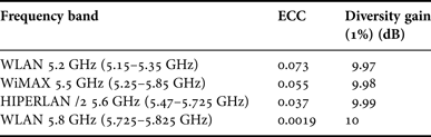
The ECC and diversity gain at 1% of probability level by <0.1 dB are listed in Table 3. The calculated result in Table 3 satisfy the criteria of low correlation (ρ e < 0.5), and good diversity performance can be expected in practical multipath environments.
Table 3. Diversity performance of MIMO antenna system.
IV. CONCLUSION
A MIMO antenna for WLAN (5.2 GHz/5.8 GHz), WiMAX (5.5 GHz), and HiperLAN/2 (5.2 GHz/5.6 GHz) applications has been proposed. It provides a broad bandwidth (670 MHz) and a high isolation (better than 26 dB) between the radiating elements. Its high performances are due to inserting a small ground plane technique between the PIFA and the PCB. Parametric investigation has been proposed to analyze the effect of different PIFA parameters on the operating frequency and the S-parameters. Good radiation characteristics and diversity performance over the operating bands have been observed.
Experimental results have been done and shown a good agreement with simulation. The results of the mutual coupling and the radiation pattern allowed achieving the good diversity characteristics of the proposed MIMO antenna.
Raefat Jalila El Bakouchi was born in Morocco, in 1987. She received her Bachelor of sciences (3 years study after the baccalaureate) in Electrical Engineering from Cadi Ayyad University, Marrakesh Morocco, in 2008. She received her Master of Science and Technology (M.Sc. Tech. (Eng)) in Electrical Engineering, Cadi Ayyad University; Marrakesh Morocco, in 2010. She is currently working toward the Ph.D. degree at the Department of Applied Physics, Electrical Systems and Telecommunications Laboratory, Cadi Ayyad University of Marrakesh, Morocco. Her research interest includes telecommunications and antennas.
 Marc Brunet Engineer in electronics at the Electronics and Telecommunications Institute of Rennes (IETR-UMR 6164), Ecole Polytechnique of the University of Nantes France, IETR, Nantes, France.
Tchanguiz Razban Haghighi Professor at the Department of Electronic and Digital Technologies, and Head of International Relations Office of Ecole Polytechnique of the University of Nantes France, IETR, Nantes, France. His research interests in the field of high frequency electronics.
Abdelilah Ghammaz received his Doctor of Electronic degree from the National Polytechnic Institute (ENSEEIHT) of Toulouse, France, in 1993. In 1994 he went back to University Cadi Ayyad of Marrakech – Morocco. Since 2003, he has been a Professor at the Faculty of Sciences and technology, Marrakech, Morocco. His research interests in the field of electromagnetic compatibility and antennas.