


1. INTRODUCTION
Plasma channeling is one of the most fascinating off-shoots of laser plasma interaction research, due to its potential applications in laser guiding in atmosphere (Alexeev et al., Reference Alexeev, Ting, Gordon, Penano, Sprangle and Briscoe2005; Woste et al., Reference Woste, Frey and Wolf2006) particle acceleration (Geddes et al., Reference Geddes, Toth, Van Tilborg, Esarey, Schroeder, Bruhwiler, Nieter, Cary and Leemans2004; Kumar et al., Reference Kumar, Pandey and Tripathi2010) transportation of ion beams (Penache et al., Reference Penache, Niemann, Tauschwitz, Knobloch, Neff, Birkner, Geißel, Hoffmann, Presura, Penache, Roth and Wahl2002), in the development of X-ray lasers (Chou et al., Reference Chou, Lin, Lin, Lin, Wang and Chen2007; Zhao et al., Reference Zhao, Xie, Wang and Liu2008) etc. To date, however, laser propagation has been severely limited by the lack of a controllable method for extending the propagation distance of the focused laser pulse. The ensuing short propagation distance results in low-energy beams with 100% electron energy spread, less amount of X-ray generation etc, which limits potential applications. Butler et al. (Reference Butler, Gonsalves, McKenna, Spence, Hooker, Sebban, Mocek, Bettaibi and Cros2003) and Mocek et al. (Reference Mocek, McKenna, Cros, Sebban, Spence, Maynard, Bettaibi, Vorontsov, Gonsavles and Hooker2005) showed that in order to achieve a large X-ray output, large gain region is required and for this purpose, the formation of plasma waveguide is crucial as it could maintain a small pump beam size over a long distance.
An intense laser pre-pulse propagating through a gas mixture of hydrogen and Ar ionizes both the gases through tunnel ionization with maximum density on axis. As the density of eight times ionized Ar is less than hydrogen atoms, Ar density plays little role in channel formation. After the passage of the first pulse, the hydrogen plasma expands radially forming a density profile with maximum on the axis. Durfee and Milchberg (Reference Durfee and Milchberg1993) and Durfee et al. (Reference Durfee, Lynch and Milchberg1995) showed that when a main laser pulse propagates through such a channel, it self focuses inside the channel and guided over distances of many Rayleigh lengths. This self focused second pulse tunnel ionizes the remaining Ar atoms. For single state ionization of atoms one requires laser intensity, I L ≥ 1014 W/cm2 at which the electric field of the laser becomes comparable to the coulomb field of the atom. For second, third, and higher states of ionization higher laser intensities (I L ≥ 1016 W/cm2) are required. The lasers employed for this purpose have finite spot size and the intensity distribution in the transverse plane is usually Gaussian. Such a laser causes non uniform tunnel ionization, maximum on the laser axis and weaker ionization as one move away from the axis. The refractive index of such plasma is minimum on the laser axis (say z axis) and increases with radial co-ordinate r. Such a channel causes refraction divergence of the laser, superimposed over the diffraction divergence. As a result the laser intensity falls off as it propagates forward and the length of the ensuing tunnel ionized plasma column is limited. The channel causes refraction divergence of the X-ray radiation too and limits the X-ray laser gain. Durfee and Milchberg (Reference Durfee and Milchberg1993) successfully created a plasma waveguide, with minimum plasma density on axis, and demonstrated that the intense laser pulses can be guided more then 20 Rayleigh lengths in plasma by using two pulse techniques. Durfee et al. (Reference Durfee, Lynch and Milchberg1995) showed that guiding does not rely on particular channeled intensity, and multiple pulses may even be guided. Milchberg et al. (Reference Milchberg, Durfee III and Lynch1995) demonstrated that the plasma waveguide is a promising means to produce efficient compact soft X-ray laser. They exploit the nonequilibrium behavior of the plasma to generate population inversion. A 1014 W/cm2, 100 ps guided pump pulse is sufficient to generate a substantial transient inversion in Ne-like Ar. Rocca et al. (Reference Rocca, Shlyaptsev, Tomasel, Cortazar, Hartshorn and Chilla1994) demonstrated the X-ray amplification with a mixture of Ar and Hydrogen. A gain of 0.6 cm−1 was obtained in the 46.9 nm line of Ne-like Ar in plasma column up to 12 cm in length (αl = 7.2) generated by compact capillary discharge. Gizzi et al. (Reference Gizzi, Galimberti, Giulietti, Giulietti, Tomassini, Borghesi, Campbell, Schiavi and Willi2001) studied the relativistic laser interactions with preformed plasma channels and observed γ-ray measurements. Kumar and Tripathi (Reference Kumar and Tripathi2005) studied the tunnel ionization of a gas up to a second ionization. Verma and Sharma (Reference Verma and Sharma2009) formulated the theory of tunnel ionization of a gas by two pulse technique and showed how laser propagate within the plasma channel. Yu et al. (Reference Yu, Cao, Yu, Cai, Xu, Yang, Lei, Tanaka and Kosama2009) did particle-in-cell simulations and observed plasma channeling by multiple laser pulses in homogeneous and inhomogeneous plasmas. Panwar and Sharma (Reference Panwar and Sharma2009) developed an analytical formalism of self focusing and self-phase modulation of an intense short pulse laser in plasma channels. Chou et al. (Reference Chou, Lin, Lin, Lin, Wang and Chen2007) demonstrated a dramatic enhancement in X-ray lasing by using an optically preformed plasma waveguide. They also demonstrate high-threshold low-gain transition at 46.9 nm in Ne-like Ar. Zhao et al. (Reference Zhao, Xie, Wang and Liu2008) reported the enhancement of Ne-like Ar at 46.9 nm by mixing appropriate Helium ratio at low pressure by the plasma channeling process. Gopal et al. (Reference Gopal, Sharma and Tripathi2000) studied the temporal evolution of the laser plasma channeling in high Z plasmas embedded with light ions.
In this paper, we propose the use of excessive hydrogen (or a low z gas) in X-ray laser to achieve radiation guiding. The scheme involves two laser pulses. The first laser has intensity just sufficient to fully ionize hydrogen but only singly ionize high Z gas, say Ar via tunneling. The second pulse of much higher intensity is launched after a time delay. During the delay period, the light mass hydrogen ions and electrons expand radially creating a plasma channel with refractive index maximum on axis. The second laser thus propagates through the preformed plasma channel and causes further ionization of Ar. The Ar loses eight electrons from its outermost shell to acquire Ne-like stable configuration and could emit X-rays. This paper focuses on the temporal evolution of high ionization states of a high Z gas in a channel created by the pre-pulse. In Section 2, we discussed the density evolution by a mixture of gases by pre-pulse. In Section 3, we develop a model for the plasma channel formation by a pre-pulse. In Section 4, we study focusing of second pulse in the plasma channel and then multiple ionization of high Z gas by the second pulse and proposed the X-ray laser gain by the two pulse technique. In Section 5, we discuss the results.
2. DENSITY EVOLUTION OF A MIXTURE OF GAS BY A PRE-PULSE
Consider the propagation of a laser pulse in a high atomic number gas (Ar) of density n mA and atomic number Z, embedded with hydrogen of density n mH. The electric field of the laser can be written as
where k ≅ ω/c,

As the pulse propagates it causes ionization of hydrogen and single state ionization of Ar via tunnel ionization process. The densities of ionized hydrogen n H and singly ionized Ar n A evolve as
and
where


Eqs. (5) and (6) represents the tunnel ionization coefficients, where I H and I A are the ionization potentials for hydrogen and Ar, ![]() are the characteristic atomic fields of hydrogen and Ar.
are the characteristic atomic fields of hydrogen and Ar. ![]() is the Planck's constant,
is the Planck's constant, ![]() is the amplitude of the laser field, m is the rest mass of the electron, e is the magnitude of electron charge. In the paraxial ray approximation we write
is the amplitude of the laser field, m is the rest mass of the electron, e is the magnitude of electron charge. In the paraxial ray approximation we write

and separate out different powers of r in Eqs. (3) and (4),


and

where τ = Γ0t and ![]() , I A is the ionization potential of Ar, a 0 = A 1 /E A is the normalized laser amplitude. We plotted Eqs. (7), (8), (9), and (10) for parameters: a 0 = 0.2, I H/I A = 0.8630, ω pHm02 /ω 2 = 0.05 and ω pAm02 /ω 2 = 0.0005. Figure 1 shows the variation of normalized axial density of hydrogen and Ar ions with time. We have taken the ratio of hydrogen and Ar atoms to be 10:1. The axial density initially increases linearly up to 35 fs and then saturates. The first pulse can only singly ionize the mixture and further ionization of Ar is not possible by the first pulse.
, I A is the ionization potential of Ar, a 0 = A 1 /E A is the normalized laser amplitude. We plotted Eqs. (7), (8), (9), and (10) for parameters: a 0 = 0.2, I H/I A = 0.8630, ω pHm02 /ω 2 = 0.05 and ω pAm02 /ω 2 = 0.0005. Figure 1 shows the variation of normalized axial density of hydrogen and Ar ions with time. We have taken the ratio of hydrogen and Ar atoms to be 10:1. The axial density initially increases linearly up to 35 fs and then saturates. The first pulse can only singly ionize the mixture and further ionization of Ar is not possible by the first pulse.

Fig. 1. (Color online)Variation of normalized axial density of hydrogen and Ar ions with time. For parameters: a 0 = 0.2, I H /I A = 0.8630, ω pHm02 /ω 2 = 0.05, ω pAm02 /ω 2 = 0.0005.
Figure 2 shows the variation of ω pH22 /ω 2 and ω pA22 /ω 2 as a function of time. These quantities for about 8 fs attain a peak and approaches 0 with time. After the passage of the first pulse, electrons and hydrogen ions begin to diffuse radially outward on a time scale ≈ r 0/c s, where c s is the speed of sound. The Ar ions are too heavy to respond to the fs time scale. The electron can cause ionization of hydrogen atoms on their way, creating an electron density profile as
where ω p02 = ω pH02 + ω pA02 and ω p22 is on the order of ω p02 after a time ≈r 0/c s. This density profile can guide electromagnetic radiation.
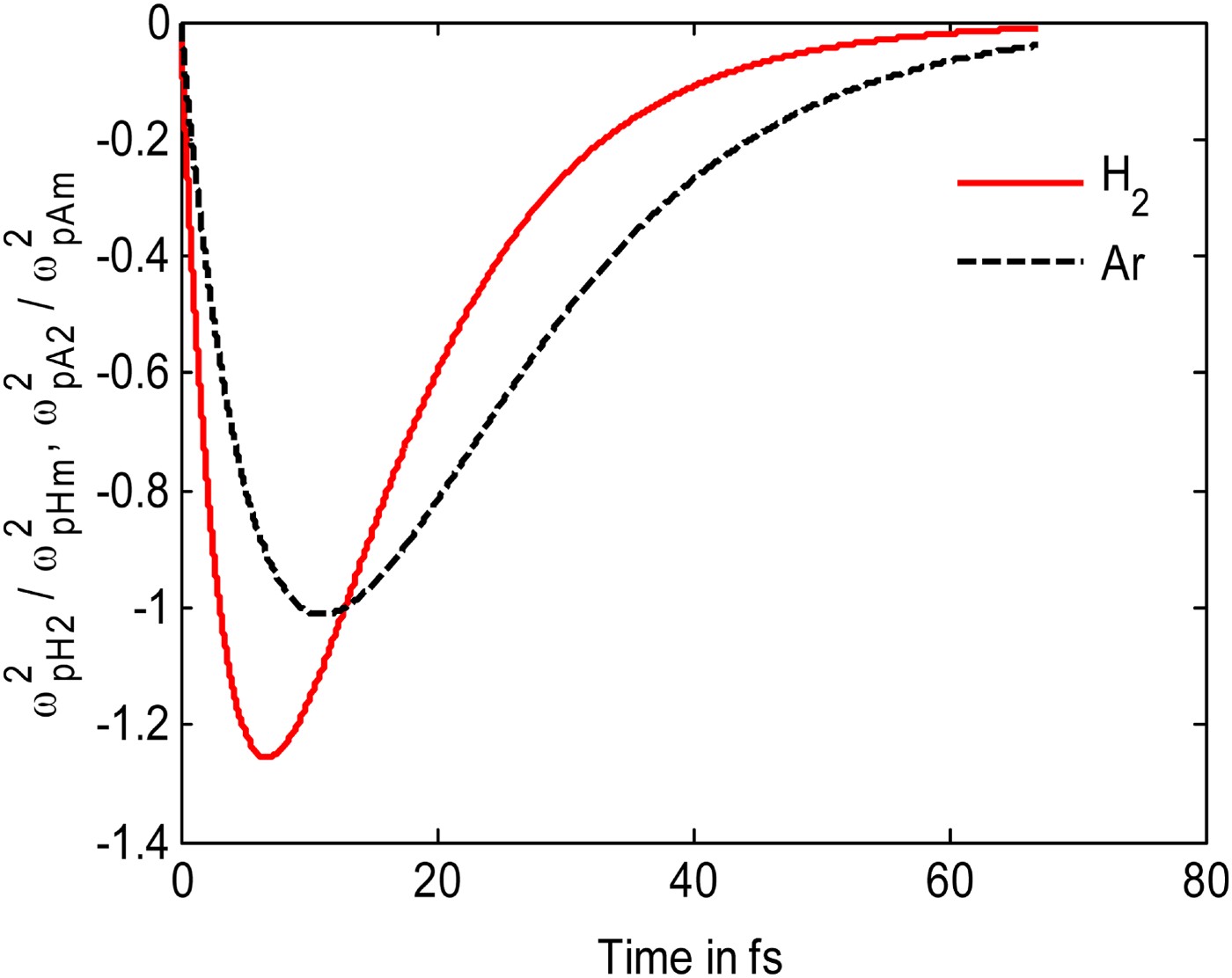
Fig. 2. (Color online)Variation of normalized radial density of hydrogen and Ar ion with time. Other parameters are same as of Figure 1.
If one considers the propagation of an electromagnetic wave ![]() , through such a parabolic density profile, then the wave equation governing
, through such a parabolic density profile, then the wave equation governing ![]() takes the form
takes the form
![{\partial^2 A \over \partial r^2} + {1 \over r} {\partial A \over \partial r} + \left[{{\omega}^2 - {\omega}_{\,p0}^2 \over c^2} - k^2 - {{\omega}_{\,p2}^2 \over c^2} {r^2 \over r_0^2} \right]A = 0. \eqno\lpar 12\rpar](https://static.cambridge.org/binary/version/id/urn:cambridge.org:id:binary:20151021093404826-0094:S0263034611000188_eqn12.gif?pub-status=live)
Defining ξ = r/r 0/,r 0/ = r 0c/ω p2, λ = (ω 2 − ω p02 − k 2c 2 )r 0//c 2, this equation takes the form
This equation offers Lagurre polynomial solutions with appropriate Eigen values. For the fundamental mode λ = 1,
If the electromagnetic wave of radius r 0 is to be guided in the channel without convergence or divergence than one need ω p2 = c/r 0.
3. PLASMA CHANNEL FORMATION
After the passage of the first pulse, the plasma begins to diffuse in a time on the order of t d = r 0/c s, where ![]() is the sound speed, T e is the electron temperature and m i is the ion mass. Immediately after the first pulse, the plasma density may be taken as
is the sound speed, T e is the electron temperature and m i is the ion mass. Immediately after the first pulse, the plasma density may be taken as

with spot size of the laser immediately after the pulse a 10 ≤ r 0. One may refer this time as t = 0.
For t > 0, one may model the electron density to evolve as
![\eqalign{n &= n^{\prime}_0 \left(1 + {r^2 \over a^2} \right)+ \left[n_0 \left(1 - {r^2 \over a_{10}^2} \right)- n^{\prime}_0 \left(1 + {r^2 \over a^2} \right)\right]\cr &\quad \times \exp \lpar - t/\tau_d \rpar \comma \; } \eqno\lpar 16\rpar](https://static.cambridge.org/binary/version/id/urn:cambridge.org:id:binary:20151021093404826-0094:S0263034611000188_eqn16.gif?pub-status=live)
where a > a 10 is the width of the density profile at t > τd. Figure 3 shows the variation of normalized density n/n 0, with respect to the normalized radial distance, r/r 0 for parameters r 0 = 10 µm, n 0 = 3.5 × 1018 cm−3, λ = 1.064 µm, and T e = 100 eV at t/τd = 0 to 4. These parameters corresponds to the experiment Durfee and Milchberg (Reference Durfee and Milchberg1993) and Durfee et al. (Reference Durfee, Lynch and Milchberg1995) As time passes on the density on the axis decreases while at off axis points it increases. The profile that evolves in the central region is similar to the one obtained by Durfee and Milchberg (Reference Durfee and Milchberg1993) and Durfee et al. (Reference Durfee, Lynch and Milchberg1995). The time for which density is a minimum comes out to be t/τd > 2.6. The density minimum on the axis shows the formation of plasma channel. For time t/τd ≤ 2.6 density is not minimum on axis and decreases with increasing value of r/r 0. Hence in a two pulse experiments for the practical realization of any application of the plasma channel, one should impinge the second pulse at time t/τd > 2.6 for the above parameters.

Fig. 3. (Color online)Variation of normalized electron density n/n 0 with normalized radial distance r/r 0 for different time t/t d. The parameters are: r 0 = 10μm, n 0 = 3.5 × 1018 cm−3, λ = 1.064 μ m, and T e = 100eV at t/τd = 0 to 4.
4. SELF FOCUSING OF THE SECOND PULSE AND MULTIPLE IONIZATION OF ARGON
Consider the propagation of a more intense second laser pulse after a time delay t p > t d, with respect to the first pulse. The electric field of the second pulse is
where A 2 = 0 for (t – z/c) < 0 and A 2 = A 200 exp (−r 2/2r 02) for (t − z/c) > 0. The pulse causes further ionization of Ar up to the charge state Ar+8, when Ar acquires a Ne-like structure. However, we presume that the modification in the channel electron density due to the ionization of Ar is marginal. The pulse duration of the second pulse is τ < t d. It undergoes focusing in the channel created by the first pulse.
The wave equation governing the propagation of the second pulse
where ω p2 = 4π ne 2/m.
In the Wentzel-Kramers-Brillouin approximation, we get
![\eqalign{&2ik_2 \displaystyle{{\partial A_2 } \over {\partial z}}+\displaystyle{{2i{\omega}_2 } \over {c^2 }}\displaystyle{{\partial A_2 } \over {\partial t}}+\nabla_ \bot ^2 A_2+i\displaystyle{{\partial k_2 } \over {\partial z}}A_2+\displaystyle{i \over {c^2 }}\displaystyle{{\partial {\omega}_2 } \over {\partial t}}A_2 \cr &\quad =\displaystyle{{A_2 } \over {c^2 }}\left[{{\omega}_p^2 - {\omega}_{\,p0}^2 } \right]\comma \; } \eqno\lpar 19\rpar](https://static.cambridge.org/binary/version/id/urn:cambridge.org:id:binary:20151021093404826-0094:S0263034611000188_eqn19.gif?pub-status=live)
Combining the first and fourth, and the second and fifth term of Eq. (19), defining t′ = t − z/c, z′ = z. We can write Eq. (19) as
Writing A2 = A 0 exp(iS), where A 0 (t′,z′,r) and S(t′,z′,r) are real and separating real and imaginary parts we get.
![\eqalign{& - \displaystyle{{2{\omega}_2 } \over c}\displaystyle{{\partial S} \over {\partial z^{\prime}}}A_0+\displaystyle{{\partial ^2 A_0 } \over {\partial r^2 }}+\displaystyle{1 \over r}\displaystyle{{\partial A_0 } \over {\partial r}} - \left({\displaystyle{{\partial S} \over {\partial r}}} \right)^2 A_0 \cr &\quad =\displaystyle{{A_0 } \over {c^2 }}\left[{{\omega}_p^2 - {\omega}_{\,p0}^2 } \right]\comma \; } \eqno\lpar 22\rpar](https://static.cambridge.org/binary/version/id/urn:cambridge.org:id:binary:20151021093404826-0094:S0263034611000188_eqn22.gif?pub-status=live)

In the near axis approximation (r 2 ≤ r 02f 2), we expand the eikonal as S = S 0 (z′) + S 2 (z′)r 2/r 02. Further we introduce a function f(z′) such that
Solving Eqs. (22) and (23) by using Eq. (24), gives the equation of the beam width parameter as
where
![\eqalign{N_2 &=\displaystyle{{{\omega}_{\,p2}^2 } \over {{\omega}_2^2 }}=\displaystyle{{n^{\prime}_0 } \over {n_0 }}\displaystyle{{r_0^2 } \over {a^2 }}\left({1+\displaystyle{{r^2 } \over {a^2 }}} \right)\cr &\quad +\left[{\displaystyle{{r_0^2 } \over {a_0^2 }}\left({1 - \displaystyle{{r^2 } \over {a_0^2 }}} \right)- \displaystyle{{n^{\prime}_0 } \over {n_0 }}\displaystyle{{r_0^2 } \over {a^2 }}\left({1+\displaystyle{{r^2 } \over {a^2 }}} \right)} \right]\exp \lpar - t/t_d \rpar \comma \; }](https://static.cambridge.org/binary/version/id/urn:cambridge.org:id:binary:20151021093404826-0094:S0263034611000188_eqnU2.gif?pub-status=live)
ω p22 = 4πn 2e 2/m, we have taken both lasers of the same frequency i.e., ω 22 = ω 2 = 4πn 0e 2/m, n 2 = (∂n/∂r 2)r 02 , ξ = z′/R d , R d = ω r 02/c and η = ω r 0 /c.
We solve Eq. (25) numerically for parameters r/r 0 for parameters r 0 = 10 µm, n 0 = 3.5 × 1018 cm−3, λ = 1.064 µm, and T e = 100 eV at t/τd = 0 to 4. Figure 4 shows the variation of beam width parameter of the second pulse f with normalized axial distance of propagation ξ. For time t/τd = 0, the value of f increases very fast with increasing ξ. This shows that the second pulse defocuses if impinges on the preformed plasma at time t/τd = 0. As the value of t/τd increases defocusing decreases and a time comes when focusing starts, i.e., after time t/τd > 2.6, N 2 is “ + ” hence focusing starts. At this time second laser self focuses in the channel, its intensity increases and hence it tunnel ionizes the remaining Ar atoms up to higher charged state, usually leaving eight electrons in the outermost occupied orbit. Such atoms appear like Ne but have energy difference between successive orbits. Some of these atoms go to excited states via collisions and one may achieve population inversion between a metastable state and the ground state. Stimulated de-excitation of atoms from the excited state to ground state could give rise to coherent X-ray generation.

Fig. 4. (Color online)Variation of beam width parameter f with normalized axial distance ξ for different time t/t d. The parameters are: r 0 = 10 μm, n 0 = 3.5 × 1018 cm−3, λ = 1.064 μm, and T e = 100eV at t/τd = 0 to 4.
Now we examine the evolution of different stages of ionization of Ar. Let n 1, n 2, n 3, n 4, n 5, n 6, n 7 and n 8 be the densities of singly, doubly, triply … up to eight ionized state at any instant t. The density evolution of different charge states can be written as
where the rate of tunnel ionization of an atom to the j, the state of ionization is given as

ω pj2 = 4 π n je 2m, j = 1,2,… and I 1, I 2 … are the ionization potentials for single, double and higher states of ionization of Ar, ![]() is the characteristic atomic field for different states,
is the characteristic atomic field for different states, ![]() is the Planck's constant,
is the Planck's constant, ![]() is the amplitude of the laser field, m is the mass of the electron, e is the magnitude of electronic charge. We expand ω pj2 = ω pj02 + ω pj22r 2 /r 0′2, collecting the coefficients of various powers of r in Eq. (26) to (32), we get
is the amplitude of the laser field, m is the mass of the electron, e is the magnitude of electronic charge. We expand ω pj2 = ω pj02 + ω pj22r 2 /r 0′2, collecting the coefficients of various powers of r in Eq. (26) to (32), we get


similarly, we obtain the 3rd, 4th, 5th, 6th, 7th density equations, Eq. (8) is obtained as follows


where ![]() and
and ![]() .
.
We solve coupled Eqs. (34)–(39) numerically for the following parameters: a 0 = 5, I H/I A = 0.8630, ω pHm02 /ω 2 = 0.05, ω pAm02 /ω 2 = 0.0005. In Figure 5, we plotted the normalized axial density of Ar ions in different states of ionization as a function of time. Initially all the Ar ions are singly ionized. When the second intense laser pulse impinges the preformed plasma, double ionization begins i.e., ω p202/ω pAm2 starts increasing and simultaneously the density of the first state Ar ions begin to decrease very quickly. This happens since the second ionization occurs from the first state ionized ions or may be from the neutral ones. Density of the second ionized Ar ions reaches a peak value and starts to decrease and hence the density of the fourth ionized Ar ions starts increasing. This happens for other higher charges i.e., as time progresses the density of the other charged states increases. Ar acquires Ne-like configuration i.e., Ar8+ state. In the figure, the value of ω p802 /ω pAm2 increases. After some fs time, it reaches a maximum value, and then saturates, which shows that no further ionization takes place. The seventh and eighth charged states are very low populated, i.e., very few ions can reach the eighth charged state. Those eight charged state ions when coming to ground state emit X-rays. Figure 4 show that as the laser propagates inside the plasma it ionizes, the remaining Ar atoms and hence its energy loses initially hence it defocuses. As values of ξ increases, and when the beam power is greater than the threshold for self-focusing, the self-convergence effect dominates over divergence effect and hence beams size of the laser shrinks i.e., beam starts to focus. The oscillatory behavior is caused by the competing nature of self-focusing and diffraction divergence. If the beam radius decreases the diffraction effects become stronger. The nonlinear self-focusing effect also increases but at a slower rate due to the saturating effect of nonlinearity. After a while the diffraction effect dominates and the beam acquires a minimum radius and then diverges. This behavior is reproduced periodically.

Fig. 5. (Color online)Variation of axial density of different charge states of Ar ions with time. For parameters: a 0 = 5, I H /I A = 0.8630, ω pHm02 /ω 2 = 0.05, ω pAm02 /ω 2 = 0.0005.
4.1. X-ray Gain
Here we have proposed that plasma channeling can help in efficient X-ray radiation. The electrons in eighth charge state populate the metastable state. Their stimulated transition to lower states leads to the generation of X-rays. Let E 2 and E 1 be the relevant energy levels of Ar8+for X-ray lasing with the ion densities N 1 atoms in ground state E 1 and N 2 in excited state E 2. Number of ions in higher energy state N 2 depends on the initial density and the temperature of the gas. Let X-ray signal of Intensity I 0 is launched at z = 0, then after passing through the mixture of gases, at distance z the change in intensity can be written as
![]() , or
, or
One can write
Where ![]() , is the gain coefficient. We find the gain coefficient for parameters (N 2 − N 1 )/N 1 = 2, N 1 ≈ 1019 cm−3, B 21 = 8.79 × 1020 cm3 erg−1 s−1 for Ne–like Ar. The gain coefficient is found to be α ≈ 0.6 cm −1.
, is the gain coefficient. We find the gain coefficient for parameters (N 2 − N 1 )/N 1 = 2, N 1 ≈ 1019 cm−3, B 21 = 8.79 × 1020 cm3 erg−1 s−1 for Ne–like Ar. The gain coefficient is found to be α ≈ 0.6 cm −1.
5. DISCUSSION
The inclusion of a low Z gas in X-ray laser appears to be an effective means to increase the gain length. The light gas, e.g., hydrogen ionized fully by a pre-pulse of intensity ~1014 W/cm2. The high Z atoms also undergo single state ionization by it. The electron and light ions of such plasma, after the passage of the pre-pulse, expand radially outward and form a plasma waveguide with electron density minimum on axis. Thus the low Z gas helps in the formation of plasma channel. When second pulse passes through this channel self focuses. Due to self focusing pulse intensity increased and hence can ionize the remaining Ar atoms. The heavy ion remains practically immobile. The second pulse of intensity ≥ 1016 W/cm2 quickly ionizes the heavy ions to higher charged states.
Due to the second intense pulse the density of first ionized Ar ions decreases very quickly. Simultaneously density of secondly ionized Ar ions increases and attains a peak value. As the Ar2+ attains peak value the density of Ar3+ ions starts increasing and simultaneously density of Ar2+ ions decreases. By this process density of Ar4+, and other higher charged states increases where as density of previous charge state decreases and finally Ar8+ charge state reached and saturates. Since no further ionization is there for Ar gas. Thus Ar acquires Ne like configuration and in the process to coming to ground states radiates in the X-ray regime.
Thus we have concluded that the low Z gas helps in plasma channel formation and this channel can now be used for the efficient X-ray radiation.
ACKNOWLEDGMENTS
The authors are grateful to Prof. V. K. Tripathi, IIT Delhi for fruitful discussions. Updesh Verma is very thankful to the Govt. Degree College Bilaspur, Rampur (U.P.) and CSIR for financial support.


