Published online by Cambridge University Press: 06 March 2006
In this paper we present the analytical description of two processes dealing with the skin-layer ponderomotive acceleration method of fast ion generation by a short laser pulse: ion density rippling in the underdense plasma region and generation of ion beams by trapped electromagnetic field in plasma. Some numerical examples of hydrodynamic simulation illustrating these processes are shown. The effect of using the laser pulse consisting of different frequency components on the ion density rippling and on phenomena connected with trapped electromagnetic field is analyzed.
The skin-layer ponderomotive acceleration (S-LPA) mechanism (Hora et al., 2002; Badziak et al., 2004a, 2004b) is proposed to explain the observed features of ion beams produced at the interaction of a subrelativistic intensity (≤ 1018 W/cm2), high-contrast, ultrashort (≤ 1 ps) laser pulse with a solid target. S-LPA assumes that electrons in the thin preplasma layer created in front of the target are accelerated by the ponderomotive force near the critical density surface where a mirror reflection takes place. Since ions are too heavy to be accelerated in the same way, the longitudinal electric field between electrons and ions plays a crucial role and has to be considered to explain motion of ions. S-LPA requires electrons to be closely attached to ions (the Debye length is much less than the thickness of accelerated plasma block). For subrelativistic laser intensities, this assumption is well justified. Experiments performed with sub-joule (1 ps) laser pulses interacting with different targets at intensities up to 2 × 10¹⁷ W/cm2, showed that in the backward and forward direction, high density ion beams (plasma blocks) are generated (Badziak et al., 2004a, 2005). The ion current densities measured in these experiments reached high value, about 1010 A/cm2. In experiments by Cang et al. (2005) and Glowacz et al. (2004), numerical calculations were presented which showed that parameters of ion beams observed in the experiments can be explained by the S-LPA mechanism. The density rippling process was recognized from numerical studies in 1974 at the University of Rochester (Hora, 1991, Figs. 10.10 and 10.11; Hoffmann et al., 1990; Asthana et al., 2000; Purohit et al., 2003; Saini & Gill, 2004), as the result of partial standing waves where the nonlinear (ponderomotive) forces pushes plasma faster to the nodes and than the other plasma dynamics would straighten the motion. The theory (Hora & Aydin, 1992) confirmed this mechanism and how this could be overcome by laser beam smoothing, especially by broad band irradiation (Hora & Aydin, 1992, 1999; Boreham et al., 1997; Osman et al., 2004). The following approach is specifically directed to analyze new developments in the plasma block generation (Hora et al., 2002; Badziak et al., 2004a, 2004b), as an alternative scheme for laser fusion (Hora, 2004; Osman et al., 2004), to be considered as one option of fast ignition (Bauer, 2003; Deutsch, 2004; Mulser & Bauer, 2004; Mulser & Schneider, 2004; Osman et al., 2004; Ramirez et al., 2004; Hoffmann et al., 2005; Badziak et al., 2005).
The interaction of laser light with preplasma in the underdense region causes density rippling which prevents laser energy from being transported and deposited near the critical density. This results in the deterioration of the parameters of ion beams which are generated near the critical density surface. Methods of smoothing density rippling were described by Hora and Aydin (1992, 1999) and Boreham et al. (1997). In this paper, we present an analytical description of processes dealing with broad band picosecond laser smoothing. This smoothing method on ion beams generation will also be shown.
To find the longitudinal electric field between electron and ion fluids the Maxwell equations:


and the Ohm's law:


must to be considered (ωp—plasma frequency). The electric and magnetic fields of standing wave in plasma without collisions and ion current density connected with quiver motion can be described by:


where: E0 is the amplitude of the electromagnetic wave, cf is the phase velocity. The electrons' movement in the direction of the laser light (x—direction) appears due to the Lorentz force (ponderomotive force): Using (7) and (8) we obtain

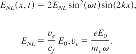
The Lorentz force causes the longitudinal electric field between electron and ion fluid to appear. This field is described by Eqs. (3) and (5). Taking Eqs. (9) and (10) into consideration, the equation for the longitudinal electric field can be obtained:

Using complex notation and assuming that Ex(x,t) has the form:

we obtain equation for the amplitude Ex(t):

This pendulum-like equation can be solved analytically. Since ions are too heavy to follow oscillation of the longitudinal electric (oscillation with characteristic frequencies of Eq. (13)—the laser frequency and the plasma frequency), the time average of Ex(t) is important as ions' movement is to be considered. The time average longitudinal electric field does not depend on the initial condition of Eq. (13) and is given by:

The value of the amplitude of the time average longitudinal electric field is given by Eq. (10). Since νe cannot exceed the velocity of light and phase velocity is higher than the velocity of light, the amplitude of longitudinal electric field is less than the amplitude of the laser field. However, the above expression does not include any relativistic effects and are valid only when νe is much less than c.
Bearing in mind the time average longitudinal electric field caused by the motion of electrons, we can consider equations describing the behavior of ions due to this field. Without any simplifications these equations have the form:


where 〈Ex(x,t)〉 is given by Eq. (14), νep is the velocity of proton fluid, mp and np are the proton mass and ion (proton) number density, respectively. During a few moments after the standing wave is switched on (we assume that ion velocity at the beginning is equal to zero and the inhomogeneity of the initial plasma is small), pressure and square term of the Lagrange derivative on the left side of Eq. (15) can be omitted. In this case, we obtain equations describing the rippling of ion density:


It is possible to solve the equation of continuity without the simplification made in Eq. (18). However, the omission of square term of Lagrange derivative causes severe restriction. Solution of Eqs. (17) and (18) are given by:

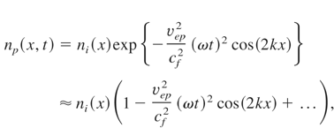
where:

Let us consider two intensities to show the order of νep; for I = 1016 W/cm2, νep is equal to 6.4 × 10⁵ m/s; for I = 1017 W/cm2, νep is equal 2.0 × 10⁶ m/s. The above expressions describing the rippling are valid when:

This condition expresses mathematically what has just been described as “a few moments after the standing wave is switched on.” Up to this moment, E0 was the arbitrary amplitude of the electromagnetic wave in plasma. Now let E0 be the amplitude of a wave in a vacuum. If homogenous plasma is considered, the following transformation in all the above expressions should be done:

The linearly increasing initial plasma density can also be taken into account. In this case, the “swelling” of the wave electric field should be taken into consideration:

Let us consider the last case. Then expressions describing the rippling take the form (cf = c/η):


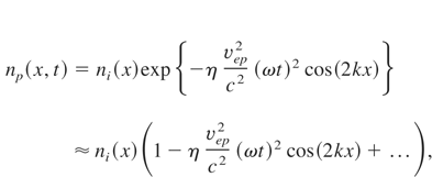

Figure 1 shows a numerical example of the rippling formation in initially increasing plasma density irradiated by the neodymium laser light. The amplitude of ion density rippling and the velocity of ions do not depend on position which is in agreement with Eqs. (26) and (27). The value of velocity amplitude of ions (∼1.5 × 10⁵ m/s) is less than νep for I = 1017 W/cm2 (2.0 × 10⁶ m/s), so condition (28) in the case illustrated in Figure 1 is fulfilled.

Numerical example showing formation of rippling in underdense plasma. Density profile (solid line) and velocity of ions (dotted line) are given at time 0.65 ps after laser light (I = 1017 W/cm2, τL = 1 ps) starts to irradiate hydrogen plasma with linearly increasing density. Initial temperature of protons and electrons is 100 eV.
Restrictions of (22) or (28) are caused by exclusion of vpx(∂/∂x)vpx term in Eq. (15). Let us try to find the stationary solution of the motion of ions in the longitudinal electric field (9) with this term, but at first neglecting pressure. The following set of equations should be taken into consideration:


Eq. (29) is fulfilled by the following function:

Expressions describing the stationary solution of ion motion in plasma without pressure caused by the electromagnetic standing wave are given by:
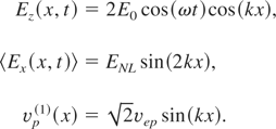
The situation described by the above equations is possible when the electromagnetic wave is trapped in plasma between two critical densities (the soliton-like structure). The second critical density is created near the initial critical density by the rippling process described in Section 2. The spatial period of the function (32b) is two times smaller than the spatial period of solution (32c). To give physical meaning to (32a–32c), only one spatial period (32b) should be taken into consideration, for example: (−π/2 < kx < π/2). In Figure 2 the plot of functions (32a–32c) is shown. This corresponds with the situation when the electromagnetic wave is trapped in plasma deformed by the ion density rippling (E0 is now the amplitude of trapped electromagnetic field).

Functions corresponding with (32a–32c) describing the soliton-like structure in plasma without pressure: i.e., the electric field of the electromagnetic wave trapped in plasma at time t = 0, the time average longitudinal electric field and the solution of (29)—ion velocity profile.
At kx = ± π/2 there is the discontinuity which can be analyzed by taking pressure into account. Non-physicality of the solution of Eq. (29) without pressure is seen also when Eq. (30) is considered: everywhere where ion velocity becomes zero the density goes to infinity. For example, at kx = 0 there occurs decompression and ion density should become zero instead of infinity.
Let us consider the equation describing the stationary motion of ions without neglecting pressure:

ions' number conservation is described by Eq. (30). Since pressure is taken into consideration, the equation of state of ion fluid should be given. The adiabatic process in an ideal gas is assumed:


Eqs. (30) and (33) were solved under the assumption that the impact of pressure is small everywhere, excluding regions near kx = 0 and kx = ± π/2. This can be expressed mathematically by the condition vTp << vep (vTp—the initial ion thermal velocity). Solution of Eq. (33) is then given by:
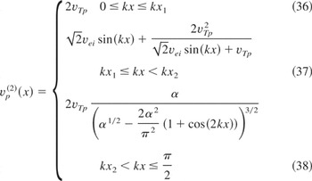
where:

The plot of the above function for laser intensity I = 1017 W/cm2 and for initial ion temperature Tp = 30 eV is shown in Figure 3.

Plot of function v(2) (x) p for I = 1017 W/cm2 and for T = 30 eV. The values for kx ∈ (−π/2,0) are given from the symmetry of the problem.
Since thermal velocity is small in comparison with vTp, changes of ion velocity shape are not significant except near k = 0, ± π/2. To show the impact of pressure on the shape of ions velocity, numerical calculations were performed in case when 1 ps neodymium laser pulse of intensity I = 1017 W/cm2 irradiates hydrogen plasma of high initial ion temperature Tp = 1 keV. Figure 4 shows ion number density and ion velocity profile created 2.2 ps after laser started to interact with plasma.

Ion density (solid line) and ion velocity (dashed line) profile 2.2 ps after neodymium—glass laser (I = 1017 W/cm2) started irradiate hydrogen plasma of the initial temperature Tp = 1 keV.
At kx = 0 decompression appears; at kx = π/2 compression takes place—ion temperature and ion number density increase. Let us consider the last case in a more detailed way. On the basis of the presented model, it can be seen that the compressed plasma moves in two directions: into vacuum (backward direction) and into plasma interior (forward direction) with the thermal velocity of compressed ions. We can calculate the maximum ion number density:

and the maximum temperature of the compressed ions:

Effectiveness of the adiabatic plasma compression is described by the dimensionless coefficient α given by Eq. (39). Let us consider neodymium-glass laser to show the order of α. For the amplitude of the electromagnetic wave in vacuum and the initial plasma temperature kBTp = 100 eV we obtain, for example: α = 6.4 for I = 1016 W/cm2 (E0 = 2.7 × 10¹¹ V/m), α = 20.2 for I = 1017 W/cm2 (E0 = 8.7 × 10¹¹V/m).
Pressure consideration also allows calculating the ion current density produced by the soliton–ion number density is given by (40); velocity of ion motion is obtained from formula (38) for kx = π/2:
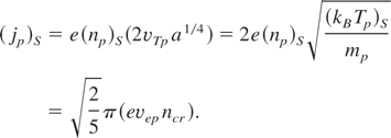
From Eqs. (40 to 42) it is seen that the motion of ions caused by the trapped electromagnetic wave is characterized by the initial ion temperature and the value of the amplitude of the soliton electric field (E0). This amplitude—as numerical calculations show—is usually less than the amplitude of the electric field of light a wave in vacuum. Additionally, it decreases because of the energy transmission from the soliton to ions and because of the plasma trap expansion (ions move in the opposite direction). However, the changes of the electric field are small and the assumption that E0 does not vary during and after the steady state creation is valid.
Let us consider a case when 1 ps neodymium glass laser pulse of intensity I = 1017 W/cm2 interacts with hydrogen plasma of initial temperature T = 100 eV. Figure 5 illustrates the ion number density profile and the electric field trapped between two critical densities at 1.7 ps. The amplitude of the electric field of the soliton-like structure is in this case equal to about 5 × 10¹¹ V/m. For this value, from Eqs. (39 to 42) we obtain:

. Figure 6 shows the ion velocity profile and the ion number density at 2.4 ps. In this case: the maximum ion current density is equal to ∼4.4 × 10¹⁰ A/cm2; the amplitude of stationary ions motion is equal ∼1.5 × 10⁶ m/s, which is in good agreement with values obtained from analytical calculations. However, the ion number density obtained by numerical calculation is less than these one obtained analytically. It can be explained by a very high ion density gradient which takes place in this process and numerical problems to maintain such a gradient.

Ion density (straight line) and trapped electric field (dashed line) 1.7 ps after neodymium glass laser I = 1017 W/cm2 started to irradiate hydrogen plasma of initial temperature Tp = 100 eV. The amplitude of trapped electromagnetic field (∼5 × 10¹¹ V/m) is not much less than the one of wave in vacuum (8.7 × 10¹¹ V/m).

Ion density (straight line) and ion velocity profile (dashed line) at 2.4 ps after neodymium glass laser I = 1017 W/cm2 started irradiate deuterium plasma of initial temperature T = 100 eV.
The ion density rippling process described in Section 2 results in the increase of reflection from plasma before mirror reflection from the critical density (Boreham et al., 1997; Jablonski et al., 2005). This causes only a small part of the laser pulse to be trapped near the critical density. Rippling can be attenuated when the laser pulse consists of not only one frequency component. Let the electric field of wave be built of m components with different frequencies:

where:

For the laser pulse constructed in this way, the time average longitudinal electric field equals:

Eq. (44) is valid when the following conditions are satisfied:

The first condition of (45) allows assuming that the wave numbers kn (n = 1, 2,…m) can be approximated by k0. It also has an effect upon the critical density for each component of (43), as it does not differ much from the critical density for ω0. In order to use the time average of the electric field for different components, the second condition is necessary. For the time average longitudinal electric field given by (44), expressions describing rippling have the form:


From (47) it can be seen that, in comparison with (26, 27), ion density rippling decreases like 1/m. Figure 7 shows the result of the numerical calculation performed for the laser light combined with three waves (Δω0 = 0.5% ω0). The ion number density shape and the ion velocity profile 0.8 ps after electromagnetic field started to interact with plasma is presented. In comparison with Figure 1, which shows the result of the interaction of one frequency component laser light, it is seen that even though the time of the interaction is longer, the ion density rippling is smaller.

Ion density (solid line) and ion velocity profile (dashed line) 0.8 ps after the laser pulse consisted with tree frequencies components (ω—neodymium laser, Δω = 0.5% ω0) started to irradiate hydrogen plasma of initial temperature and initial ion density profile as in Figure 1.
Since the time average longitudinal electric field is also responsible for the processes described in Sections 3 and 4, it is possible to obtain the expressions for the soliton-like structure created by the laser pulse consisting of different frequencies (43). In this case, the values corresponding with vep and with the coefficient α are given by:


It is seen that the velocity (48) and the coefficient α(m) describing the ion compression decrease like the square root of m—slower than the ion density rippling (47).
Basing on (48) and (49) it is possible to calculate (compare with (40–42)):
1. the maximum ion density:

2. the maximum ion temperature:

3. the maximum ion current density:

The effectiveness of the decrease in ion density rippling can be expressed not only by reflectivity changes but also by the value of the electric field amplitude of the soliton-like structure. Figure 8 shows the ion density and the ion velocity profile created by the electromagnetic field at time 1.5 ps. In this case, electric field amplitude of soliton was about 1.5 × 10¹² V/m. The time necessary for the creation of the steady-state is smaller than in the case when laser pulse consists of only with one frequency component—it is also the effect of decreasing rippling. Using Eqs. (49–52) for E0 = 1.5 × 10¹² V/m and for the initial ion temperature Tp = 100 eV we obtain:

The ion amplitude velocity of stationary motion obtained by numerical calculation is about 2.5 × 10⁶ m/s; maximum ion current density obtained in this case equals about 7.8 × 10¹⁰ A/cm2 which is in good agreement with analytical calculations.

Ion density (solid line) and ion velocity profile (dashed line) at 1.5 ps after laser pulse consists of tree frequencies (ω0—neodymium laser, Δω = 0.5% ω0) started to irradiate hydrogen plasma of initial temperature Tp = 100 eV and initially linearly increasing ion density profile.
It has been shown that the electromagnetic field trapped in plasma near the critical density surface can result in generation of high-current-density ion beams propagating in two opposite directions. It is possible that this phenomenon is responsible for the observed features of the ion beams measured in the experiments in which the subrelativistic, picosecond laser pulses interact with the preplasma created in the front of the solid target. More detailed numerical calculations for different properties of the initial plasma ramp (initial gradient density, initial temperature, and chemical composition of plasma) and for different laser pulse characteristics (pulse duration, intensity, and shape) should be performed to probe this possibility. Such calculations will also allow better comparison with experimental results and better understanding their physical background. Since the relativistic, subpicosecond laser pulses are technically obtainable, it would be worth investigating the impact of the relativistic phenomena on ion density rippling and on the properties of soliton-like structures produced near the critical surface.
This work was supported in part by the State Committee for Scientific Research (KBN), Poland under Grant No 1 PO3B 043 26 and by a grant for a Visiting Scientist by the University of Western Sydney, Australia..

Numerical example showing formation of rippling in underdense plasma. Density profile (solid line) and velocity of ions (dotted line) are given at time 0.65 ps after laser light (I = 1017 W/cm2, τL = 1 ps) starts to irradiate hydrogen plasma with linearly increasing density. Initial temperature of protons and electrons is 100 eV.

Functions corresponding with (32a–32c) describing the soliton-like structure in plasma without pressure: i.e., the electric field of the electromagnetic wave trapped in plasma at time t = 0, the time average longitudinal electric field and the solution of (29)—ion velocity profile.

Plot of function v(2) (x) p for I = 1017 W/cm2 and for T = 30 eV. The values for kx ∈ (−π/2,0) are given from the symmetry of the problem.

Ion density (solid line) and ion velocity (dashed line) profile 2.2 ps after neodymium—glass laser (I = 1017 W/cm2) started irradiate hydrogen plasma of the initial temperature Tp = 1 keV.

Ion density (straight line) and trapped electric field (dashed line) 1.7 ps after neodymium glass laser I = 1017 W/cm2 started to irradiate hydrogen plasma of initial temperature Tp = 100 eV. The amplitude of trapped electromagnetic field (∼5 × 10¹¹ V/m) is not much less than the one of wave in vacuum (8.7 × 10¹¹ V/m).

Ion density (straight line) and ion velocity profile (dashed line) at 2.4 ps after neodymium glass laser I = 1017 W/cm2 started irradiate deuterium plasma of initial temperature T = 100 eV.

Ion density (solid line) and ion velocity profile (dashed line) 0.8 ps after the laser pulse consisted with tree frequencies components (ω—neodymium laser, Δω = 0.5% ω0) started to irradiate hydrogen plasma of initial temperature and initial ion density profile as in Figure 1.

Ion density (solid line) and ion velocity profile (dashed line) at 1.5 ps after laser pulse consists of tree frequencies (ω0—neodymium laser, Δω = 0.5% ω0) started to irradiate hydrogen plasma of initial temperature Tp = 100 eV and initially linearly increasing ion density profile.