


Introduction
Patch antennas are widely used in communication systems due to their light-weight, low-cost, and easy fabrication. However, their working bandwidth, evaluated at 10 dB of return loss, is narrow which limits their use in actual and modern applications requiring the coverage of wide frequency bands. Therefore, lots of researches have been placed to tackle this issue by introducing techniques of bandwidth enhancement to improve the performance of patch antennas.
Several methods targeting the patch antenna bandwidth enhancement have been reported previously [Reference Yang, Yang, Hong and Li1–Reference Tiwari, Singh and Kumar Kanaujia17]. Various techniques have been employed. In [Reference Yang, Yang, Hong and Li1–Reference Rameswarudu4], slots with different shapes are etched in the antenna ground plane to enhance the impedance bandwidth by adding another resonant frequency. For instance, in [Reference Yang, Yang, Hong and Li1], two symmetric stair-slots are cut from the antenna ground plane to improve the impedance bandwidth from 2 to 6.5% centered at the operating frequency of 2.46 GHz. In [Reference Liu, Zhu and Choi5–Reference Wen, Yang, Zeng, Zou and Pan8], the antenna resonant modes are manipulated and combined to widen the working band. In this kind of antennas, shorting posts are carefully placed to control the desired resonant modes. For example, the design in [Reference Liu, Zhu and Choi5] employs two pairs of shorting pins to combine TM10 and TM30 modes resulting in 13% of impedance bandwidth without increasing the antenna profile. Another technique of bandwidth enhancement is reported in [Reference Xu, Xu, Liu, Li and Liu9–Reference Reddy, Joany, Reddy, Sugadev and Logashanmugam11] where parasitic patches are used to excite two or more resonances. By combining all the resonant frequencies, the antenna bandwidth can be broadened significantly. For instance, in [Reference Xu, Xu, Liu, Li and Liu9], a triangular radiating patch is surrounded by three parasitic patches to create two additional resonances which increase the bandwidth evaluated at 10 dB of return loss to 13.8%. In [Reference Cai, Wang, Zhang, Wang, Zong and Xu12, Reference Nasimuddin, Chen and Qing13], the antenna bandwidth enhancement is achieved by loading metamaterials. An example is illustrated in [Reference Cai, Wang, Zhang, Wang, Zong and Xu12] where magneto-electro-dielectric planar waveguided metamaterials are proposed to manipulate the effective permeability and effective permittivity which leads to 2.07 times bandwidth improvement compared with a conventional patch antenna. Indeed, the antenna bandwidth is enhanced by adjusting the geometrical parameters of the complementary spiral ring resonators (CSR), etched on the radiating patch, and the embedded Hilbert-line (EHL) which is adopted in the antenna ground plane. In [Reference Zhang, Zhu, Wu, Liu and Wu14, Reference Yasin and Baktur15], the bandwidth enhancement is achieved through proximity coupling. For instance, in [Reference Yasin and Baktur15], 2.5 times improvement in the impedance bandwidth is realized through proximity coupling of the feed line and three meshed square patches. The designs mentioned above exhibit good performances. However, etching slots in the ground plane may limit the antenna practicality as it cannot be placed on metallic structures. Besides, using shorting posts or metamaterial structures may increase the fabrication complexity. On the other hand, the proximity coupling method does not realize a very wide bandwidth. Therefore, we propose simple designs of patch antennas with bandwidth enhancement. The technique employed is based on creating additional resonances by loading strips onto the corner of one radiating edge. The main contributions of the proposed antennas are listed below:
• The antennas’ working bandwidth is adjusted easily by changing the lengths of the “L” and “T” strips, based on the proposed design guidelines;
• The proposed antennas exhibit circular polarization which may increase the transmitting rate compared with the conventional patch antenna with linear polarization;
• Theory of characteristic modes (CMs) is employed to explain the circular polarization behavior;
• The proposed antennas can be placed on metallic surfaces as no slots are etched in the ground plane;
• The proposed “L” strip antenna has the added merit of high-stability gain over the entire working bandwidth;
• The fabrication complexity is reduced as no shorting posts or metamaterials are used;
• The patch antennas’ bandwidth is increased significantly without increasing their profiles or their overall sizes.
The geometry of the proposed antennas and the working mechanism are investigated and explained carefully in Section “Antenna's geometry and working mechanism” of this paper. The simulated and measured results of the fabricated prototypes are compared and discussed in Section “Simulated and measured results”. The conclusion of this work is shown in Section “Conclusion”.
Antenna's geometry and working mechanism
Patch antenna loaded with an inverted “L” strip
The geometry of the proposed antennas is shown in Fig. 1 and the corresponding dimensions are given in Table 1. The substrate used in this work is of type F4B with a relative permittivity of (ɛr = 2.55), a loss tangent of (tan (α) = 0.002), and a thickness of (h = 2 mm). A probe feed is employed for the RF feeding of the antenna. The impedance matching is controlled easily by adjusting the feed position F p1. The back side of the antenna is fully grounded. The antenna resonates at an arbitrary frequency f = 5.1 GHz before loading the “L” strip. The length of the patch L p is obtained using the following equation:

where λgp is the guided wavelength. The inverted “L” strip is loaded onto the corner of one radiating edge to create an additional resonant mode which can be combined with the patch's fundamental mode to broaden the antenna bandwidth. A parametric study consisting of sweeping the length of the inverted “L” strip is carried out to understand the working mechanism. Figure 2 shows the reflection coefficient —S 11— when the length L 1is tuned. The software used to perform all the simulations is HFSS. According to Fig. 2, the fundamental resonant mode of the patch antenna remains stable around 5.1 GHz while the additional resonant frequency, created by the inverted “L” strip, decreases when L 1 increases. It is found that the value which realizes a wide bandwidth corresponds to L 1 = 9.5 mm. The additional resonant mode can be tuned easily without affecting much the main patch mode by varying the length L 1. The resonant frequency (f L) created by the inverted “L” strip can be approximated by the following equations:


Where c is the free space velocity, ɛr is the relative permittivity, and h is the substrate thickness. We note that the above equations serve just as initial guidelines for the design of the patch antenna with inverted “L” strip. One can readjust the operating frequency by simple tuning of L 1.

Fig. 1. Geometry of the proposed antennas. (a) Patch antenna loaded with inverted “L” strip, (b) Patch antenna loaded with inverted “T” strip, (c) side view.

Fig. 2. The reflection coefficient —S 11— when L 1 is tuned.
Table 1. The dimensions of the antennas (mm)

The current distribution of the antenna with an inverted “L” strip is depicted in Fig. 3. We note that at the higher frequency f L = 5.41 GHz, the electric current is more concentrated on the inverted “L” strip.

Fig. 3. The current distribution at the resonant frequencies of the patch antenna loaded with an inverted “L” strip: (a) 5.1 GHz, (b) 5.41 GHz (L 1 = 9.5 mm).
To demonstrate that the antenna preserves stable gain, the simulated realized gain and the simulated axial ratio are plotted in Fig. 4. According to Fig. 4, the antenna realized gain is stable around 7.3 dBi over the whole bandwidth evaluated at 10 dB of return loss. Indeed, the “L” strip aids in radiation, as the radiation pattern is stable over the entire working bandwidth. What is more, the antenna exhibits circular polarization in the band 5.26–5.41 GHz (2.8%) as the axial ratio is less than 3 dB. The theory of characteristic modes (CMs) is employed to analyze the behavior of the antenna when the “L” strip is loaded. The contribution made by a particular mode to the total antenna radiation is described by the modal significance (MS) which is a function of the eigenvalue λ. The MS can be expressed as follows [Reference Boukarkar, Lin, Yu, Mei, Jiang and Yu18]:


Fig. 4. The simulated realized gain and axial ratio of the patch antenna loaded with inverted “L” strip.
The value of λ decides whether the mode is considered at resonance or not. We note that a resonance is characterized by λ = 0 which results in MS = 1. Before loading the “L” strip, the original patch antenna exhibits a fundamental vertical mode, denoted by J VO, at 5.1 GHz. The modal significance, as well as the characteristic current distribution, are shown in Fig. 5. It is noted that MS = 0.99 at 5.1 GHz with the characteristic current concentrated vertically along the radiating surface. When “L” strip is loaded, the current circulation is disturbed and two modes are excited at the same operating frequency. The corresponding modal significance and characteristic current distributions are demonstrated in Fig. 6. It is noted the excitation of two orthogonal modes, one vertical mode (J VL) and one horizontal mode (J HL). The circular polarization (CP) can be excited when these two orthogonal modes have the same MS [Reference Chen and Wang19]. According to Fig. 6, the “L” loaded patch antenna exhibits a circular polarization around 5.3 GHz.

Fig. 5. The modal significance and the characteristic current distribution of the original patch antenna

Fig. 6. The modal significance and the characteristic current distributions of the patch antenna loaded with the “L” strip.
The proposed patch antenna, loaded with inverted “L” strip, has the merits of wide bandwidth, stable gain, circular polarization, and low profile. For further improvement of the operating bandwidth, an inverted “T” shape strip is loaded.
Patch antenna loaded with an inverted “T” strip
A microstrip line of length L 2 is added to the “L” strip to form the inverted “T” shape strip. The purpose behind this loading is to add another resonant frequency which can be combined with the resonances excited by the patch antenna as well as the inverted “L” strip. A parametric study is carried out to investigate the influence of tuning the length L 2 on the antenna reflection coefficient.
Figure 7 demonstrates the simulated —S 11— when L 2 is tuned. It is noted that, by adjusting the length L 2 adequately, the three resonant frequencies can be combined to realize a wide bandwidth. The following equations serve as initial design guidelines to evaluate the additional resonant frequency denoted by f T:


The frequency f T can be tuned easily by adjusting the length L 2 without affecting much the two other resonances f and f T. It is found that L 2 = 7.6 mm realizes a wider bandwidth.

Fig. 7. The reflection coefficient —S 11— when L 2 is varied
The current distribution of the antenna loaded with an inverted “T” strip is depicted in Fig. 8. We note that the concentration of the electric current varies when the frequency increases based on the excited strip. The simulated realized gain and axial ratio are shown in Fig. 9. We note that in about 80% of the working bandwidth, the gain is stable and its value varies slightly around 7 dBi.

Fig. 8. The current distribution at the resonant frequencies of the patch antenna loaded with inverted “T” strip (a) f = 5.1 GHz, (b) f L = 5.41 GHz, (c) f T = 5.72 GHz.

Fig. 9. The simulated realized gain and axial ratio of the patch antenna loaded with inverted “T” strip.
The theory of characteristic modes (CMs) is used to explain the behavior of the “T” strip antenna in the working bandwidth. The “T” strip antenna is a combination of two “L” strip antennas with different lengths. The “T” loaded antenna exhibits two circular polarization (CP) bands. The first CP band, from 5.25 to 5.42 GHz, is created based on the analysis of “L” strip antenna for the modal significance shown in Fig. 6. When another “L” strip, with different length, is combined with the previous one to create the “T” shape strip, another CP is created from 5.74 to 5.78 GHz. Indeed, two additional orthogonal modes, denoted by J VT and J HT, are excited and their amplitudes are equal around the frequency 5.75 GHz with an MS of 0.86.
Figure 10 illustrates the reflection coefficient of the conventional patch antenna, the patch antenna loaded with the inverted “L” strip, and the patch antenna loaded with the inverted “T” strip. It is noted that the working bandwidth is significantly enhanced compared with the original patch antenna.

Fig. 10. The simulated —S 11— of the conventional patch antenna and the proposed two patch antennas.
After discussing the working mechanism and design guidelines of the proposed antennas, the next step is devoted to the investigation and comparison of the simulated and measured results.
Simulated and measured results
Patch antenna loaded with an inverted “L” strip
The patch antenna loaded with an inverted “L” strip is fabricated, and then its reflection coefficient is measured with an Agilent N5245A PNA-X network analyzer; while the antenna radiation patterns are measured in SATIMO anechoic chamber. A photograph of the fabricated antenna with the —S 11— measured setup is shown in Fig. 11. The simulated and measured —S 11— is plotted in Fig. 12. According to Fig. 12, we note that the simulated and measured results agree well. The small discrepancies are mainly attributed to the fabrication tolerances and measurement setup. The simulated and measured radiation patterns at the center of the measured operating bandwidth (f CL = 5.38 GHz) are shown in Fig. 13. Again, the simulated and measured antenna patterns are in line. It is noted that the antenna radiation patterns are preserved unidirectional with the direction of primary radiation pointed toward θ = 0°. The summary of the measured results of the patch antenna loaded with an inverted “L” strip is displayed in Table 2. The antenna covers the frequency band 5.04–5.71 GHz (12.46%). Compared with a conventional patch antenna which covers 5.04–5.16 GHz (2.4%), the antenna loaded with “L” strip improves the operating bandwidth 5.2 times.

Fig. 11. Photograph of the patch antenna loaded with an inverted “L” strip with —S 11— measurement setup.

Fig. 12. Simulated and measured —S 11— of the patch antenna loaded with an inverted “L” strip.

Fig. 13. Simulated and measured realized gain of the patch antenna loaded with an inverted “L” strip at f CL = 5.38 GHz. (a) E-plane (YZ), (b) H-plane (XZ) (Sold line: simulated, dashedline: measured).
Table 2. Antenna loaded with “L” strip measured results

Patch antenna loaded with an inverted “T” strip
The patch antenna loaded with an inverted “T” strip is fabricated and then tested. A photograph of the antenna with the —S 11— measurement setup is shown in Fig. 14. The simulated and measured reflection coefficient is depicted in Fig. 15. The antenna loaded with “T” strip covers the operating band 5.07–5.89 GHz (15%) with good impedance matching. The proposed antenna enhances 6.2 times the operating bandwidth compared with a conventional patch antenna. The simulated and measured patterns at the center frequency of the operating band f CT = 5.48 GHz are presented and compared in Fig. 16. The summary of the measured results is displayed in Table 3.
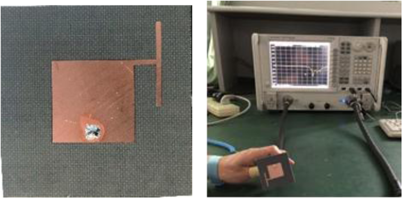
Fig. 14. Photograph of the patch antenna loaded with an inverted “T” strip with —S 11— measurement setup.

Fig. 15. Simulated and measured —S 11— of the patch antenna loaded with an inverted “T” strip.

Fig. 16. Simulated and measured realized gain of the patch antenna loaded with an inverted “T” strip at f CT = 5.48 GHz. (a) E-plane (YZ), (b) H-plane (XZ) (Sold line: simulated, dashed line: measured).
Table 3. Antenna loaded with “T” strip measured results

A comparison study between this work and some recently published patch antennas with bandwidth enhancement is given in Table 4. The sizes of the antennas are evaluated according to the lowest frequency in the working band (free space (λ0) and guided wavelength (λg)). Based on Table 4, one can find that the proposed antennas use a simple method to enhance the working bandwidth significantly. The proposed “L” loaded antenna has a similar size compared with the design shown in [Reference Xu, Xu, Liu, Li and Liu9] when considering the free-space wavelength. However, the size of the proposed “T” loaded antenna is slightly larger than the design presented in [Reference Xu, Xu, Liu, Li and Liu9]. Besides, the proposed “L” and “T” loaded antennas have larger gains compared with the design introduced in [Reference Xu, Xu, Liu, Li and Liu9]. Indeed, in [Reference Xu, Xu, Liu, Li and Liu9], a low gain value of − 1 dBi is noticed at the upper limit of the operating bandwidth. Also, the antenna shown in [Reference Xu, Xu, Liu, Li and Liu9] employs some shorting vias, which may increase the fabrication complexity. What is more, the proposed designs exhibit circular polarization that helps in increasing the transmitting rate compared with the design presented in [Reference Xu, Xu, Liu, Li and Liu9]. Compared with the antennas in [Reference Yang, Yang, Hong and Li1, Reference Liu, Zhu and Choi5, Reference Yasin and Baktur15, Reference Liu, Gao, Zhu, Ji, Yang and Zheng20] the proposed designs exhibit a wide operating range (15% when the “T” loaded antenna is selected) with reduced fabrication complexity and reduced total cost.
Table 4. Comparative study

Conclusion
In this paper, two patch antennas with bandwidth enhancement are proposed. A simple technique consisting of loading inverted “L” and “T” strips is adopted. The patch antenna loaded with an inverted “L” strip covers the frequency band 5.04–5.71 GHz (12.46%), while the patch antenna loaded with an inverted “T” strip exhibits acceptable performances in the working band 5.07–5.89 GHz (15%). The bandwidth of the proposed designs can be easily tuned by changing the length L 1 and L 2. Based on the selected working bands, the proposed antennas may find their use in wireless local area network (WLAN) application.
 Boukarkar Abdelheq was born in Algeria. He received the State Engineering degree in electrical engineering from the École Polytechnique, Algiers, Algeria, in 2009, and the M.S. and Ph.D. degrees from the University of Electronic Science and Technology of China, Chengdu, China, in 2015 and 2019, respectively. His current research interests include antenna design, reconfigurable RF/Microwave circuits, and MIMO systems. He has authored more than 10 papers in the field of antenna design. Doctor Boukarkar Abdelheq serves as a reviewer for the following well-known SCI journals: IEEE Antennas and Wireless Propagation Letters, IET Microwave, Antennas and Propagation, IET Electronic Letters, and International Journal of Microwave and Wireless Technologies.
 Satouh Rachdi was born in Algeria. He received the State Engineering degree and M.S. in signal processing from École Supérieure Ali CHABATI, Algiers, Algeria. His current research interests include antenna design and RF/Microwave circuits.


