


Nomenclature
- A
local speed of sound
- A
cross-sectional area
- C
blade chord length
- C
absolute velocity
- G
mass flow
- K
adverse pressure gradient
- K
constant,
 $K{\rm{ = }}\sqrt {\dfrac{\gamma }{{{R_{air}}}}{{\left(\frac{2}{{\gamma + 1}}\right)}^{\frac{{\gamma + 1}}{{\gamma - 1}}}}} $
- M
Mach number
- p
static pressure
- P*
relative total pressure
- q(M)
flux function
- r
radial co-ordinate
- R
radius of curvature
- s
streamline
-
${\dot S_{gen}}$
entropy generation rate
- SWBLI
shock wave/boundary-layer interaction
- T*
relative total temperature
- U
circumferential velocity
- V
relative velocity
- w
axial velocity component
- x
streamwise co-ordinate
-
$\rho$
density
-
$\delta$
boundary-layer thickness
-
$\tau$
wall shear stress
-
$\theta$
turning angle of blade surface
-
$\phi$
angle between the streamline and the axial direction
-
$\psi$
defect region
-
$\gamma$
ratio of specific heats
-
$\mu$
dynamic viscosity
- z
rotor axial direction


Symbols
- ps
pressure surface of rotor blade
- ss
suction surface of rotor blade
- sx
position x along streamline
- x 0
streamwise position where the wall pressure begins to rise
1.0 Introduction
Increasing the stage loading of compressor is under successive research to satisfy the thrust–weight ratio requirements of advanced aeroengine, which also leads to a considerable increase of the flow deflection angle and the tangential velocity [Reference Wennerstrom1–Reference Dunham3]. The former is limited by the rapid growth and separation of boundary layer. Thus, it is a wise choice to continuously increase the rotational speed to improve the tangential Mach number. However, the raising of relative flow velocity at inlet section for transonic compressor is accompanied by the increase of aerodynamic penalty, such as shock loss and flow separation loss induced by shock wave/boundary-layer interaction (SWBLI), which reduce the aerodynamic performance and maximum flow capacity of rotor blade. In addition, they will be accompanied by the complex strong three-dimensional (3D) characteristics of low-momentum fluids on blade suction surface in boundary layer [Reference Wennerstrom4]. Therefore, it is necessary to reduce the additional loss induced by shock foot while using the strong passage shock to raise stage loading in transonic compressors [Reference John and Holger5].
The behaviour of shock wave imposes a strong streamwise pressure gradient in the boundary layer, and the low-momentum fluids could not remain its form under strong adverse pressure gradient, which may lead to flow separation. Over the years, various control techniques of SWBLI hitherto developed include active control (boundary-layer suction, jet ejection, magnetohydrodynamic control and so on), passive control (vortex generators, cavity, shock control bump, ramp structure, etc.) and hybrid control [Reference Shuang, Shaowen, Yanping, Yufei and Fu6–Reference Gaitonde11]. The ramp structure can achieve the desired global gains by introducing relatively small modifications on the baseline model, which has a beneficial smearing effect on the position of shock foot to alter a single shock wave into a multiple shock wave configuration, thus resulting in the reduction of aerodynamic loss [Reference Jin and Zhang12–Reference Zhang, Tan, Sun and Rao14]. According to shock configuration, the ramp structure can be divided into two types. One is a more wedge-like design with an oblique shock generation, and another is a smooth profile with multiple compression waves [Reference Bruce and Colliss15]. Thus, the geometry design of the ramp structure is a significant challenge to achieve beneficial aerodynamic performance promotion without excessive stagnation pressure losses [Reference Blinde, Humble, Vanudheusden and Scarano16–Reference Lee and Loth18].
In a transonic compressor rotor, the spanwise transport is also a key flow characteristic that must be taken into account [Reference Adkins and Smith19, Reference Traub, Waghela and Bordignon20]. Because of the difference in tangential velocity components between the main flow and boundary layer, the centripetal force required for the circumferential motion of the low-momentum fluids in the boundary layer is greater than that generated by the radial adverse pressure gradient [Reference Wennerstrom21]. This radial disequilibrium leads to spanwise transport of low-momentum fluids along blade surface. It is well known that the behaviour of radial transport is to transfer substantial low-momentum fluids from the rotor hub to the tip in the boundary layer, resulting in velocity deficit and an enormous amount of loss in blade passage [Reference Turner, Gorrell and Car22, Reference Hah and Reid23]. The design objective of the ramp structure is to reduce both streamwise and spanwise flow losses while weakening the passage shock foot. However, it is puzzling to design the ramp profile with a moderate streamwise adverse pressure gradient in radial transport environment.
In order to mitigate the passage shock-induced flow separation loss, a detailed design method of the ramp structure with constant adverse pressure gradient considering the radial equilibrium effect is proposed on blade suction side surface. In addition, with the verification of the numerical computational results obtained by the Reynolds-averaged Navier–Stokes (RANS) method, the flow physics of ramp structure is investigated in more detail by analysing the flow field characteristics of baseline and improved model at peak efficiency condition and near stall condition.
2.0 Investigated model
A high-loading transonic compressor rotor NASA Rotor 37 was chosen herein as the baseline model. The rotor was originally designed and tested at the NASA Lewis Research Center in the late 1970s, and the specific geometric parameters and experimental results have been published in NASA technical reports and NATO AGARD literatures [Reference Reid and Moore24–Reference Dunham26]. Detailed design and aerodynamic parameters of the baseline transonic compressor Rotor 37 are given in Table 1.
Table 1. Key geometric and aerodynamic parameters of Rotor 37

The rotor was designed for an operating pressure ratio of 2.106 at a mass flow of 20.19kg/s, and the rotor-inlet relative Mach number varies from 1.13 at the hub to 1.48 at the tip. The operating tip clearance is estimated to be 0.356mm at the designed speed, corresponding to 0.5% of inlet span and 0.7% of exit span. The rotor has 36 multiple-circular-arc blades with a hub–tip ratio of 0.7, an aspect ratio of 1.19 and a tip solidity of 1.288 [Reference Chima27]. The relative velocity at the inlet of the rotor from the hub to the tip is supersonic, and a 3D shock wave configuration is formed at the leading edge of the blade. In addition, the impingement point of blade passage shock is about 50% of the blade chord length, and there is a strong SWBLI on the blade suction surface above 40% spans, which results in the decrease of aerodynamic performance of the rotor.
The improved rotor blade is designed originating from baseline NASA Rotor 37, a ramp profile of which is employed on blade suction surface to weaken the passage shock foot by smearing effect. Boundary-layer separation induced by shock is related to the adverse pressure gradient [Reference John and Holger5], and it is accompanied by the complex strong 3D features near blade suction surface in boundary layer. In order to obtain the moderate adverse pressure gradient on ramp curve and reduce the pre-shock Mach number, the design method of ramp curvature with constant adverse pressure gradient considering radial second flow is adopted in this paper. The improved profile and meridional streamline of compressor rotor are depicted in Fig. 1. The ramp profile OO
 $^{\prime}$
is obtained by the governing equations with a moderate adverse pressure gradient, and the curve O
$^{\prime}$
is obtained by the governing equations with a moderate adverse pressure gradient, and the curve O
 $^{\prime}$
Q is given by Bézier curve for bringing the airflow back to the blade surface smoothly. For this design method, the viscous effect is excluded first, and the boundary-layer thickness correction is applied by an empirical equation finally.
$^{\prime}$
Q is given by Bézier curve for bringing the airflow back to the blade surface smoothly. For this design method, the viscous effect is excluded first, and the boundary-layer thickness correction is applied by an empirical equation finally.
 $M{a_{{x_0}}}$
,
$M{a_{{x_0}}}$
,
 ${p_{{x_0}}}$
and
${p_{{x_0}}}$
and
 ${\theta _{{x_0}}}$
are Mach number, static pressure and wall turn angle at separation initial point O, respectively, and O
${\theta _{{x_0}}}$
are Mach number, static pressure and wall turn angle at separation initial point O, respectively, and O
 $^{\prime}$
is the terminal point of ramp profile. Considering that the low-momentum fluids in the boundary layer behind passage shock travel radially outward under the centrifugal force, the streamline deflection appears, and the angle between the streamline and the axial direction is denoted as
$^{\prime}$
is the terminal point of ramp profile. Considering that the low-momentum fluids in the boundary layer behind passage shock travel radially outward under the centrifugal force, the streamline deflection appears, and the angle between the streamline and the axial direction is denoted as
 $\phi$
. The specific design method of improved profile is shown as follows:
$\phi$
. The specific design method of improved profile is shown as follows:

Figure 1. Improved profile and meridional streamline.
Assume that the static pressure distribution on the ramp profile is
 \begin{align}p = k(x - {x_{\rm{0}}}) + {p_{{x_{\rm{0}}}}},\end{align}
where the parameter k is the adverse pressure gradient. According to the deflection angle
 $\phi$
and aerodynamic parameters at initial position O and terminal point O
$\phi$
and aerodynamic parameters at initial position O and terminal point O
 $^{\prime}$
, coupling with the pressure distribution (Equation (1)), the adverse pressure gradient k can be obtained by the radial equilibrium effect (Equation (2)).
$^{\prime}$
, coupling with the pressure distribution (Equation (1)), the adverse pressure gradient k can be obtained by the radial equilibrium effect (Equation (2)).
 \begin{align}\frac{1}{{{\rho _{sx}}}}\frac{{\partial p}}{{\partial r}} = \frac{{U_{sx}^2}}{r} - {V_{sx}}\frac{{\partial {V_{sx}}}}{{\partial s}}\sin \phi + \frac{{V_{sx}^2}}{{{R_{sx}}}}\cos \phi \end{align}
Furthermore, the Mach number distributions on the ramp can be given by Equation (3), and the relationship between the Mach number on the ramp and the wall turning angle can be derived from simple wave theory and Prandtl-Meyer function, as in Equations (4) and (5). Finally, the ramp profile is obtained by Integral Equation (6) and boundary-layer displacement thickness correction equation (Equation (7)) on a concave surface [Reference Drayna, Nompelis and Candler28]. In addition, to ensure smooth connection of the ramp curve to the blade surface, the curvature of connection point O is consistent with the baseline model. For curve O
 $^{\prime}$
Q, six intermediate points are fixed on the camber curve to construct the Bessel curve, a specified width is added perpendicularly to the camber curve and then the position of the Bézier control point for the side curve is defined.
$^{\prime}$
Q, six intermediate points are fixed on the camber curve to construct the Bessel curve, a specified width is added perpendicularly to the camber curve and then the position of the Bézier control point for the side curve is defined.
 \begin{align}{Ma^2} = \left[ {\left( {1 + \frac{{(\gamma - 1)}}{2}Ma_{{x_0}}^2} \right) \cdot {{\left( {\frac{{k(x - {x_0}) + {p_{{x_0}}}}}{{{p_{{x_0}}}}}} \right)}^{{\rm{ - }}\frac{{\gamma {\rm{ - 1}}}}{\gamma }}} - 1} \right] \cdot \frac{2}{{\gamma - 1}}\end{align}
 \begin{align}\theta = {\theta _{{x_0}}} + \nu ({Ma_{{x_0}}}) - \nu (Ma)\end{align}
 \begin{align}\nu (Ma) = \sqrt {\frac{{\gamma + 1}}{{\gamma - 1}}} \arctan \sqrt {\frac{{\gamma - 1}}{{\gamma + 1}}({Ma^2} - 1)} - \arctan \sqrt {({Ma^2} - 1)} \end{align}
 \begin{align}f(x) = \int {\tan \theta } \end{align}
 \begin{align}\delta (x) = Ax + Bx{e^{ - x}} \\[-4pt] \nonumber\end{align}
For the improved model, six blade spans are set along the whole blade radial, namely 0%, 20%, 40%, 60%, 80% and 100% spans. The ramp structure is located near the shock-impingement point on the blade suction surface, and the starting position corresponds to that of the shock-induced flow separation of each blade span. According to other researchers’ experience [Reference Bruce and Colliss29, Reference Ogawa and Babinsky30] and numerical simulation results, the length of ramp is upstream influence length (the location where the wall pressure starts to rise to the shock foot in the inviscid-flow model) of SWBLI at design rotor speed, and they are 3.1%, 3.5%, 6.1%, 7.2%, 7.9% and 6.2% of each blade span chord length, respectively. The detailed geometric parameters of ramp profile of six blade spans with constant adverse pressure gradient are summarised in Table 2. Since the initial position of ramp curve is the same as that of passage shock wave-induced boundary-layer separation, after completing blade profile with ramp profile of six spans, the improved blade model is established by radially stacking all the spans along the centroid of each blade aerofoil smoothly with B-spline curves. The comparison of blade profiles at mid span and blade models is shown in Fig. 2.
Table 2. Detailed design parameters of ramp profile


Figure 2. Comparison of blade profiles at mid span and rotor blade models.
3.0 Numerical validation
The 3D numerical calculation software ANSYS CFX 14 was used for the study in this paper. This code, based on the finite volume method and the fully implicit solution strategy, was used to solve the compressible RANS equations. The solver has been demonstrated to be capable of accurately predicting the overall performance of the compressor rotor, and the deviation between numerical results and experimental data meets the accuracy requirement for many compressors [Reference Epsipha, Mohammad and Kamarul31, Reference Biollo and Benini32]. Furthermore, the further evaluation of flow field characteristics captured by this code for transonic compressor rotor was conducted in Refs (Reference Biollo and Benini33) and (Reference Qizar, Mansour and Goswami34). Very good agreements with experimental data are obtained regarding the flow field characteristics of shock-induced boundary-layer separation and the distributions of Mach number in blade passage for a transonic compressor rotor. These studies indicate that the CFX solver is capable of accurately capturing the aerodynamic performance and flow field characteristics of transonic compressors.
The 3D computational meshes of rotors are generated by commercial software AutoGrid 5. In order to improve the quality of the grids, the topology type of HOH is adopted. An O-shaped block is used around the blade, and four H-shaped blocks are used at the inlet and outlet computational domain inside the blade passage. The computational domain is divided into five blocks, namely inlet block, blade-skin block, outlet block, inner block and butter-fly block. For the meshes in tip clearance, the butterfly-type topology is applied to deal with the periodical connection grids. Figure 3 shows the topology and mesh in calculation domain. The mesh size in the boundary layer is crucial for accurate prediction of numerical results. Therefore, the height of the first layer mesh from the blade surface is 1 × 10⁻⁶m to ensure the first cell y+ < 1. Total temperature, total pressure and flow angle are set at the inlet plane consistent with experimental conditions [Reference Dunham26]. The hub, shroud and blade surface are set as no-slip and adiabatic wall boundary. Besides, rotational periodicity is used for the circumferential sides. The overall performance curve of the rotor can be obtained by varying the outlet pressure.

Figure 3. Topology and mesh in calculation domain.
The grid independence study has been conducted via variations of the grid nodes in the calculation domain. The height of the first layer mesh from the blade surface remains 1 × 10⁻⁶m, and the node quantity of each block increases in proportion to the increment of the whole mesh quantity. The distribution curves of adiabatic efficiency and total pressure ratio at peak efficiency point with different grid resolutions are shown in Fig. 4. With the increase in the grid node number in the calculation domain, the adiabatic efficiency and the total pressure ratio slowly rise until the total number of grid nodes reaches 2.3 m. For the number of grids from 2.3 to 2.6 m, the deviation of adiabatic efficiency and total pressure ratio are 0.03% and 0.05%, respectively, which are both less than 0.1%. Therefore, the 2.3-m grid resolution is adequate for the prediction of overall performance and flow field characteristics for Rotor 37.

Figure 4. Adiabatic efficiency and total pressure ratio with different grid resolutions.
In order to evaluate the impact of turbulence model on the calculation results analysis on numerical results with k-Epsilon (k-
 $\varepsilon$
) model, k-Omega (k-
$\varepsilon$
) model, k-Omega (k-
 $\omega$
) model and Shear Stress Transport (SST) k-
$\omega$
) model and Shear Stress Transport (SST) k-
 $\omega$
model has been performed on design rotor speed with the experimental data in detail, including overall performance and flow field characteristics, as illustrated in Fig. 5. Among the three turbulence models, the k-
$\omega$
model has been performed on design rotor speed with the experimental data in detail, including overall performance and flow field characteristics, as illustrated in Fig. 5. Among the three turbulence models, the k-
 $\varepsilon$
turbulence model agrees best with the experimental data, with the maximum deviation of the total pressure ratio and adiabatic efficiency no more than 3%. The spanwise distributions of total pressure ratio and total temperature ratio using different turbulence models show that the calculated profile using the k-
$\varepsilon$
turbulence model agrees best with the experimental data, with the maximum deviation of the total pressure ratio and adiabatic efficiency no more than 3%. The spanwise distributions of total pressure ratio and total temperature ratio using different turbulence models show that the calculated profile using the k-
 $\varepsilon$
turbulence model matches well with the experimental results, as illustrated in Fig. 6. In addition, a comparison of relative Mach number distributions within blade passage at 70% span and 95% span using k-
$\varepsilon$
turbulence model matches well with the experimental results, as illustrated in Fig. 6. In addition, a comparison of relative Mach number distributions within blade passage at 70% span and 95% span using k-
 $\varepsilon$
turbulence model is shown in Fig. 7. It shows that the numerical results can predict shock location and boundary-layer separation flow characteristics well, as well as the detailed distributions of Mach number in blade passage, implying that the numerical simulation method used herein can accurately predict the overall performance and flow characteristics of the transonic compressor rotor.
$\varepsilon$
turbulence model is shown in Fig. 7. It shows that the numerical results can predict shock location and boundary-layer separation flow characteristics well, as well as the detailed distributions of Mach number in blade passage, implying that the numerical simulation method used herein can accurately predict the overall performance and flow characteristics of the transonic compressor rotor.

Figure 5. Numerical results with different turbulence models at design condition.

Figure 6. Spanwise distributions of aerodynamic parameters with different turbulence models.

Figure 7. Relative Mach number distributions within blade passage at peak efficiency point.
4.0 Results and discussion
4.1 Rotor blade performance
The prediction of overall performance for both of the two rotor blades is plotted in Fig. 8. It shows that the adiabatic efficiency and total pressure ratio of improved rotor are increased by 1.09% and 3.2%, respectively, at peak efficiency point compared with the baseline rotor, and they are also improved at near stall point as well. In addition, in terms of stabilizing operating range, the stall margin of improved rotor is increased over 0.12%, implying that the improved model with ramp structure behaves with a wider operating range and better aerodynamic performance than the baseline model.

Figure 8. Aerodynamics performance of two rotors at design rotor speed.
The distributions of flow deflection angle obtained by mass averaged method along spanwise for both rotor blades at peak efficiency point are shown in Fig. 9. The distance from the inlet plane to the blade leading edge is axial chord length, and the outlet plane is 0.75 axial chord length downstream of the blade trailing edge. The result shows that improved model rotor has greater flow deflection than baseline rotor along the blade span, implying that the energy conversion capability of transonic compressor from mechanical energy to air flows is enhanced. In addition, the increase in the magnitude of airflow deflection is basically the same from blade root to tip, accounting for about 10% of the baseline rotor airflow deflection angle.

Figure 9. Distributions of flow deflection angle for two rotor blades at peak efficiency point.
In addition, the maximum flux capacity of improved rotor is also promoted, and the choking mass flow is 0.58% higher than that of the baseline rotor. According to Equation (8), the mass flow of compressor is determined by axial velocity, density and flow area at blade passage aerodynamic throat. For the transonic compressor Rotor 37, the aerodynamic throat is located downstream of the impingement point of the passage shock. A weaker SWBLI and smaller boundary-layer separation region can increase the area of aerodynamic throat and reduce the blockage effect within the blade passage. The blockage is generally caused by the reduction in the main core flow region due to velocity defect. In order to intuitively reveal the blockage, the defect region of two rotors at aerodynamic throat section is shown in Fig. 10. The defect region is determined by using the gradients of the product of velocity and density in the radial and circumferential directions with a positive cut-off value, as in Equation (9) [Reference Suder35, Reference Ren and Gu36]. For the flow field within the blade passage of two rotors, the ineffective regions are mainly concentrated in the tip, blade and hub surfaces, and the defect region on the blade suction side of the improved rotor is 6.8% less than that of the baseline rotor. The reduction of the defect region also implies the decrease of flow loss caused by the low-momentum fluids to some extent.
 \begin{align}G = \rho \cdot {C_{\rm{z}}} \cdot A = K \cdot \frac{{{P^ * }}}{{\sqrt {{T^ * }} }} \cdot A \cdot q(M)\end{align}
 \begin{align}\psi = \left| {\frac{{\partial \rho w}}{{\partial r}}} \right| + \left| {\frac{{\partial \rho w}}{{\partial \theta }}} \right| \ge cutoff\end{align}

Figure 10. Velocity defect region of two rotors.
4.2 Flow physics inside blade passage
4.2.1 Peak efficiency point
Although numerical calculation with RANS method is unable to accurately predict the parameters in the boundary layer, the results can display a qualitative trend agreement well with experimental data [Reference Bulat and Bulat37, Reference Sun, Scarano, Oudheusden, Schrijer, Yan and Liu38]. Thus, comparisons and analyses of flow field characteristics based on RANS method are feasible to reveal the flow physics of ramp structure. According to the aerodynamic performance curves of both rotors, adiabatic efficiency and total pressure ratio of improved model are greatly increased than baseline model at peak efficiency point. Detailed flow physics across the ramp structure is further analysed through the flow fields. For the transonic compressor rotor, the SWBLI mainly occurs in the region above mid blade spans. In order to intuitively show the variations of shock configuration and intensity in the blade passage, the shock function contours have been employed at 40%∼80% spans, as shown in Fig. 11. The shock function is defined by Equation (10), representing the compression degree of airflow. Compared with the baseline model, it is easily found that the ramp structure just alters local flow field near passage shock, and it has little effect on the main flow field of blade passage. A series of compression waves appear on the ramp profile, weakening the passage shock foot, and the location of shock-impingement point on blade suction surfaces moves downstream. The variation of shock configuration at passage shock foot increases the length of the compression region and mitigates the penalty incurred by the local strong shock wave without reducing the airflow pressure rise in the main flow region of the blade passage.
 \begin{align}S{\rm{ = }}c\frac{{\nabla p \cdot \overrightarrow V }}{{p \cdot a}}\end{align}

Figure 11. Variations of passage shock foot for two rotor blades at peak efficiency point.
In the flow physics of turbomachinery, the increase of flow loss is accompanied by the entropy generation. The more entropy production, the greater flow loss. Therefore, the loss generated by shock root region and boundary-layer separation region can be quantitatively evaluated by the entropy generation. Based on the variations of passage shock foot across the SWBLI region, the entropy production rate contours at 40%, 60% and 80% blade spans are illustrated in Fig. 12. The entropy production rate, representing the local generation rate of the irreversible loss directly, is calculated by Equation (11), which provides a useful tool to analyse the loss quantitatively.
 \begin{align}{\dot S_{gen}} = \frac{1}{T}{\tau _{ij}}\frac{{\partial {u_i}}}{{\partial {x_j}}} + \frac{\gamma }{{{T^2}}}{\left(\frac{{\partial T}}{{\partial {x_j}}}\right)^{\rm{2}}}\end{align}

Figure 12. Entropy generation rate contours at 40%, 60% and 80% blade spans of two models.
The amount of loss generation due to shock waves and boundary-layer separation can be calculated by integrating the entropy production rate in the corresponding region defined for each flow phenomenon. Before entropy production integration, the shock root region and boundary-layer separation region should be extracted separately. In this paper, we extracted these two regions by static pressure and velocity, as shown by black solid line and dotted line region in Fig. 12. It is observed that huge losses appear obviously behind the passage shock within the boundary layer on the blade suction side for two rotor models; this is mainly caused by strong passage shock-induced flow separation. However, the ramp structure of improved model alters a single passage shock into a multiple shock, which mitigates the intensity of passage shock foot as well as shrinks the boundary-layer separation region compared with the baseline model. In addition, the entropy production rate integral results of the region defined for passage foot and boundary-layer separation region show that the loss of shock root in the improved model is 5.2%, 8.6% and 6.5% lower than that in the baseline model at 40%, 60% and 80% blade spans, and the boundary-layer separation loss induced by passage shock is also reduced by 7.02%, 10.6% and 8.8%, respectively, at the corresponding blade spans. The reduction of losses caused by passage shock and shock-induced flow separation indicates that the ramp profile with constant adverse gradient has the significant potential in controlling the interaction between strong shock wave and boundary layer.
To verify the design method of ramp profile on blade suction surface, the curves of adverse pressure gradient across the SWBLI region at 50% and 80% blade spans of two rotor blades are plotted in Fig. 13. A strong adverse pressure gradient induced by passage shock appears on blade suction side of baseline rotor, while the counterpart of improved rotor blade is composed of two parts, which are induced by compression waves and weaker passage shock, respectively. The value of adverse pressure gradient caused by compression waves on ramp profile almost remains constant, and only little deviation is represented between the simulation results and expected values, indicating feasibility of design method. In addition, the maximum adverse pressure gradients induced by passage shock of improved rotor blade for 50% and 80% blade spans are 31.6% and 25.7% lower than those of the baseline rotor blade, respectively, which shows the potential of ramp structure to weaken the shock foot.

Figure 13. Adverse pressure gradient distributions of two rotors at peak efficiency point.

Figure 14. Radial flow on blade suction surface at peak efficiency point.
When the shock-induced separation takes place, there will be complex 3D flow structures within the blade passage, and a strong radial transport of low-momentum fluids will appear in the boundary-layer separation region behind the passage shock. Figure 14 depicts the radial flow on the blade suction surface of two rotor blades; the transport trend of low-momentum fluids in the boundary layer travels outward in the radial direction from the hub to the casing by the centrifugal force. As the passage shock exists on blade suction surface across the whole blade spans, the boundary-layer initial separation corresponds to the position of passage shock-impingement point along blade span on baseline suction side. The boundary-layer separation vortex on the suction surface is clearly observed, and it rolls up from 20% blade spans and extends along the blade spanwise, which forms a severe velocity defect in this region. For the improved rotor, the separation vortex is rolled up above 50% blade spans, and the boundary-layer separation region and the low-momentum fluids decreased significantly. The reduction of shock-induced separation fluids indicates that the velocity defect region is mitigated and the maximum flux capacity of the compressor rotor is increased. In addition, the adverse pressure gradient distributions along blade span behind passage shock are shown in Fig. 15. Compared with the baseline blade, the spanwise adverse pressure gradient of the improved blade is larger in the range of 40%∼70% blade spans. The increase of spanwise adverse pressure gradient can effectively counteract the effect of centrifugal force, which shows that the radial flow of the improved blade is significantly reduced.

Figure 15. Adverse pressure gradient along blade span.
Further analyses on spanwise distributions of boundary-layer thickness on blade suction side behind passage shock have been implemented. The boundary-layer thickness is the perpendicular height from the blade surface wall where the flow velocity along the wall flow direction is 99% of the main flow region velocity. According to the velocity distribution profile perpendicular to the blade suction surface and boundary-layer thickness definition, the boundary-layer thickness distribution behind passage shock along the whole blade span was obtained, as schematically shown in Fig. 16. The global distribution trend of boundary-layer thickness for two rotors, rising initially and then shrinking, presents from hub to casing, and the maximum boundary-layer thickness occurs near 70% blade span. However, the boundary-layer thickness of the baseline model grows rapidly above 20% of blade spans while that of the improved model increases over 40% blade spans, and the maximum boundary-layer thickness of the improved model decreases by 33.4% compared to the baseline model, indicating that the flow separation loss of SWBLI is reduced significantly.

Figure 16. Boundary-layer thickness on suction side behind passage shock.
4.2.2 Near stall point
In order to reveal the flow physics at near stall point, analyses on flow field characteristics within blade passages of two rotors have been implemented. Relative Mach number contours at 40%, 60% and 80% spans of two rotors near stall point are shown in Fig. 17. As the pressure increases at compressor rotor outlet, the passage shock moves away from the leading edge of the blade and forms a stronger detached shock. Since the shock-impingement position of detached shock is located ahead of the smooth ramp structure, the flow velocity is subsonic near the smooth ramp region, which has little effect on flow field ahead of detached shock for improvement. Therefore, the flow field characteristics at the front of detached shock for both rotor blades are almost the same. For the boundary-layer separation downstream of the detached shock, the flow separation region of the improved rotor is greatly diminished, and separation structure is significantly different from that of baseline rotor. The boundary-layer separation of the improved model is divided into two parts by ramp structure, which is mainly attributed to the ramp suppressing the accumulation of low-momentum fluid in the boundary layer, making the boundary-layer separation reattachment in advance.
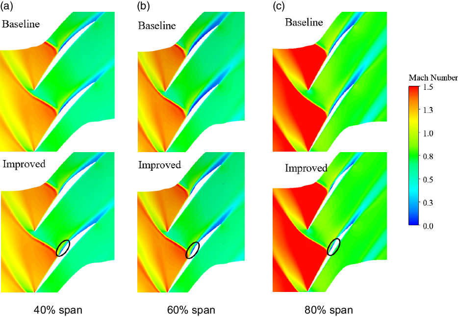
Figure 17. Relative Mach number contours at 40%, 60% and 80% blade spans near stall point.
The radial transport of low-momentum fluids in the boundary layer is illustrated in Fig. 18. The boundary-layer separation fluid behind detached shock travels outward along the blade suction surface driven by the centrifugal force for two rotors. For the baseline rotor blade, during the spanwise motion process of the separation vortex, the action region of the separation vortex extends gradually. Compared with the baseline rotor, the separation fluid of the improved rotor moves outward on the ramp profile region, and the action region of the separation vortex basically does not expand. This is mainly because the elevation of the ramp hinders the low-momentum fluids moving downstream along the streamline and restricts the evolution and extension of the separation vortex. In addition, quantitative analysis of the radial transport of fluids in the boundary layer on the blade suction side has been conducted based on the comparison of two rotor blades. The spanwise transport of fluids is mainly concentrated in two regions, the SWBLI region and near the blade trailing-edge region, marked as region S and region P, as shown in Fig. 18. The integration results of mass flow show that the total radial transport fluids of the improved rotor are reduced by 13.5% compared with the baseline rotor. In addition, the radial transport fluids of baseline rotor blades in region S and region P, respectively, account for 34.2% and 62.8% of the total radial fluids, while the proportion of radial transport fluids in the corresponding region for the improved rotor blades is 29.7% and 70.3%, respectively. Compared with baseline rotor blades, the proportion of radial fluids in the region P rises, mainly attributed to the increase of the wall deflection angle from the end of ramp structure to the trailing edge of the blade on the blade suction side.

Figure 18. Radial flow on blade suction surface near stall point.

Figure 19. Entropy contour of Rotor 37 in tip region near stall point.
The principal effect of spanwise transport is to move a substantial amount of loss from the rotor hub to tip in the boundary layer, making the hub performance appear quite good and the tip quite bad [Reference Wennerstrom21]. Near stall point, the passage shock moves away from the leading edge of the blade, forming a stronger detached shock, and the blade loading is also shifted upstream. Thus, the influence range and location of shock will change in the tip region.
To intuitively reveal the flow field characteristics in the tip region near stall point, analysis on the entropy contour of transonic compressor Rotor 37 has also been performed, as shown in Fig. 19. In transonic compressors, detached shock exists in the tip region, and the shock strongly interacts with tip leakage flow. According to previous investigations, the position of the interface between the leakage flow and the main flow is determined by the momentum balance between them. In the direction perpendicular to the interface, the momentum offset each other, thus forming a stable interface. Across the detached shock, the interface is deflected and the radius of leakage vortex increases sharply. This is mainly attributed to the variation in momentum of the main flow and leakage flow caused by the detached shock, resulting in the migration of momentum equilibrium point, and a new interface is formed.

Figure 20. Velocity streamlines released in tip region near stall point. (a) The streamlines over the first 25% chord; (b) the streamlines range from 25% to 60% chord; (c) the streamlines over last 40% chord.
The velocity streamlines of tip leakage flow for both rotors have been also carried out, as depicted in Fig. 20. The streamlines all over the entire chord are divided into three regions, namely TLFR1, TLFR2 and TLFR3, and the regions of three parts cover the leading edge of the blade to 25% of the chord, from 25% to 60% of the chord and the last 40% of the chord, respectively. The flow field characteristics of the three different chord sections are quite different. It is found that the tip leakage flow across the TLFR1 rolls up into the tip leakage vortex and moves downstream through the blade passage without impinging the neighbouring blade. The fluids in the region of TLFR2 can be divided into two parts. One part interacts with the leakage vortex and impinges on the leading edge of the neighbouring blade and moves downstream along the pressure surface of the neighbouring blade, while the other part leaks over the rotor tip for the second time and extends to the neighbouring blade passage. The flow in the section of TLFR3 forms the trailing-edge tip vortex and converges with the tip leakage vortex at the neighbouring blade trailing edge [Reference Gerolymos and Vallet39, Reference Du, Lin, Chen, Nie and Biela40]. In addition, the secondary tip leakage flow in TLFR2 also can be divided into three paths, marked as path A, path B and path C. The path A rolls into the tip leakage vortex in the neighbouring blade passage. Path B and path C interact with the tip leakage vortex at the inlet and outlet of the neighbouring blade passage, respectively.
Table 3 shows the detailed analysis of mass flow in tip leakage flow region for two models, and it is normalised by the total mass flow of the tip leakage flow of the baseline model. The total mass flow of tip leakage flow of the improved model decreases by about 1.9% compared with the baseline rotor. Furthermore, through the comparison of mass flow of each section, it can be found that the reduction of mass flow of tip leakage flow for improved model is primarily concentrated in TLFR2. This is mainly because the streamwise position of the interaction between detached shock and boundary layer is located at TLFR2, and the spanwise transport of low-momentum fluids in SWBLI region for improved model is significantly less than that of the baseline model. By contrast, the mass flow in TLFR3 of improved model exceeds the baseline rotor, which can be attributed to the increase of secondary tip leakage flow in this region (red square in Fig. 20(b)). The low-momentum fluids in the boundary layer induced by detached shock of improved model converge and transport to the tip region along the ramp structure (black square in Fig. 20(b)), and then partial low-momentum fluids flow to the neighbouring blade passage along path C through TLFR3.
Table 3. Comparison of tip leakage flow (normalised by tip leakage flow of baseline model)

5.0 Reliability analysis of results
In this paper, based on the idea of splitting a single strong shock wave into several weak shock waves, the passive control method of shock-induced boundary-layer separation in turbomachinery was investigated by numerical simulation. This idea has been verified in the intake, and the numerical results are in good agreement with the experimental results [Reference Jin and Zhang12–Reference Zhang, Tan, Sun and Rao14]. In turbomachinery, John [Reference John, Qin and Shahpar10] introduced the shock control bumps to the blade surface of transonic compressor to reduce shock wave-induced boundary-layer separation loss, as shown in Fig. 21. The results show that the shock control bumps have the ability to reduce shock loss, reduce shock-induced separation and increase both efficiency and stall margin. The effect of 3D radial flow is not considered in the design method of shock control bumps.
In this paper, based on the verification of this idea in the intake and Rotor 37 transonic compressor rotor, a smooth ramp design method with constant adverse pressure gradient on the consideration of radial flow is proposed to diminish the shock-induced flow separation loss. Numerical verification methods are described in detail in Section 3 with tolerable accuracy. In addition, the overall performance analysis based on numerical results shows that the adiabatic efficiency and total pressure ratio of the improved rotor are increased by 1.09% and 3.2% than baseline, respectively, as shown in Fig. 8. The entropy generation rate contours and other flow field characteristics in compressor blade passages are consistent with the results of overall aerodynamic performance. Therefore, the research results herein have a certain credibility. At present, we are working on the strength calculation and manufacturing of the improved compressor rotor and will conduct experimental verification in the future.

Figure 21. Relative Mach number counter of Rotor 37 at 50% span. Datum (left) and optimised (right).
6.0 Conclusions
In order to diminish passage shock-induced separation loss with the consideration of radial equilibrium effect, a detailed design method of smooth ramp structure with constant adverse pressure gradient near passage shock-impingement point on blade suction surface is brought forward to highly loaded transonic compressor NASA Rotor 37. Numerical results indicate that the aerodynamics performance of improved rotor is superior to the baseline model, and the flow physics of ramp structure is revealed by the flow fields analysis for both rotors at peak efficiency condition and near stall condition.
-
• At peak efficiency point, the strong passage shock foot of baseline rotor blades is split into compression waves and the weaker passage shock foot, which mitigates the strong adverse pressure gradient and reduces the shock-induced separation loss. In addition, the value of adverse pressure gradient caused by compression waves on ramp profile almost remains constant, indicating feasibility of design method.
-
• Further benefits are also confirmed with the distributions of spanwise aerodynamic parameters. It is found that the spanwise adverse pressure gradient of the improved blade is larger in the range of 40%∼70% blade spans, resulting in less radial transport of low-momentum fluids within the boundary layer and thinner boundary-layer thickness behind passage shock than the baseline rotor.
-
• For near stall point, the ramp structure changes the spanwise transport distribution of low-momentum fluids in SWBLI region and near blade trailing-edge region on suction surface, as well as mitigates the mass flow and mixing intensity of tip leakage flow, which improves the stall margin and aerodynamic performance to a certain extent.
The above investigations provide a supporting idea for using ramp structure with constant adverse pressure gradient to decrease the streamwise and spanwise flow loss for a transonic compressor rotor. However, more sophisticated flow characteristics of the boundary-layer separation, vortex formation and evolution processes in unsteady status, as well as the flow physics at off-design conditions are not analysed herein. More research efforts are anticipated in the future in this area.
Acknowledgements
The authors sincerely thank the National Key Research and Development Program of China (No. 2016YFB0901402) and the Key Project of National Natural Science Foundation of China (No. 51790513) for funding.


