Introduction
Radar absorbing material, which is also known as RAM, is basically a material that has been specially designed and shaped to absorb incident microwave radiation in the radar operation frequency band [Reference Choi, Lee and Lee1–Reference Teber, Unver, Kavas, Aktas and Bansal3]. In its early stages of development, the RAMs usually suffered from several practical problems, such as a narrow frequency band and incident angle sensitivity [Reference Ghayekhloo, Afsahi and Orouji4]. Hence, in the past few decades, there has been an increasing demand for high-performance RAM with wide-band and wide-angle properties for various military and civilian applications.
Until now, many different techniques, such as the frequency-selective surface (FSS) and the plasma, have been developed to meet this requirement [Reference Mishra, Khusboo and Chaudhary5–Reference Ayop, Rahim, Murad and Samsuri8]. Among these techniques, the honeycomb radar absorbing structure (RAS), which is characterized by its light weight, good strength, low density, and low dielectric constant, provides one of the greatest potentials for achieving excellent load bearing and electromagnetic energy absorbing capabilities [Reference Smith9]. Over the past decades, abundant studies have been carried out to understand and improve the electromagnetic behaviors for such an important structure, which are mostly on the honeycomb with a novel unit-cell structure [Reference Smith and Scarpa10–Reference Xie, Ji, Yang, Hou and Wang15], absorbent application and broadband optimization [Reference Xie, Ji, Yang, Hou and Wang15–Reference Khurram, Ali, Rakha, Zhou and Munir17], full-wave analysis approach [Reference Chen, Pei and Fang18, Reference Ouchetto, Majd, Ouchetto, Essakhi and Zouhdi19], effective electromagnetic parameters [Reference Quiévy, Bollen, Thomassin, Detrembleur, Pardoen, Bailly and Huynen20–Reference Johansson, Holloway and Kuester25], novel design methods [Reference Choi, Shin, Song, Lee, Lee and Kim26, Reference Choi and Kim27], and so on. However, compared with other techniques, especially artificial electromagnetic structures, such as the FSS absorber, only a few works concerning the oblique incident performance have been reported for the honeycomb RAS. In [Reference Fan, Yang and Chao28], the reflectivity of some honeycomb panels at an incident angle of 45° and with horizontal polarization was tested and the results show that the reflectivity is better than −20 dB over the whole range of 4–18 GHz. However, the absence of data for the vertical polarization and the larger incident angle make it impossible to conduct a comprehensive assessment of its wide-angle property. More detailed results for hexagonal and overexpanded honeycomb RASs can be found in [Reference Feng, Zhang, Wang and Fan29] and [Reference Wang, Zhang, Chen, Zhou, Jin and Fan30]. According to these two works, the transverse-magnetic (TM) polarization has a better wide-angle property than the transverse-electric (TE) polarization. Specifically, for a 30 mm-thick hexagonal honeycomb, a reduction in reflection of at least a 10 dB in the range of 4.6–18 GHz can be achieved for TM polarization when the incident angle is less than approximately 50° (only 25° for TE polarization). Furthermore, the honeycomb RAS will lose its radar absorbing ability and become a radar reflective structure when the incident angle is larger than 55°.
Although the existing data provide good guidance for the application of the honeycomb RAS, we are still not sure whether this will be its ultimate limit for realizing both a wide bandwidth and absorption over a wide range of angles. Recently, the graded design of the coating thickness of the honeycomb RAS was reported in [Reference Zhou, Huang, Xie, Liang, Lu and Dong31, Reference Rinaldi, Proietti, Tamburrano and Sarto32]. Then, we presented a novel design method for their graded idea based on our dispersive closed-form expression for the effective permittivity of the honeycomb RAS [Reference Zhao, Liu, Song and Xi33]. In this study, the dispersive effective permittivity formula can reduce the computational error of reflectivity by approximately 75%, and the optimizer with a normal incident objective function for wide-band application is utilized to achieve a fractional bandwidth of 141.2%, i.e., 3.1–18 GHz, for at least a 10 dB reflectivity reduction. Compared with the uniform coating technique, the graded coating design not only provides a better wide-band property but also reduces the thickness of the honeycomb RAS. Although these efforts focus only on the normal incident situation, it offers an opportunity to develop the design possibilities for the honeycomb RAS with wide-band and wide-angle properties.
In this paper, we present a graded honeycomb RAS design to develop better oblique incident performance. For both TE and TM polarization, the optimized honeycomb RAS has a fractional bandwidth of 118.6% for at least 10, 8, and 5 dB reflectivity reductions when the incident angle is <45°, 55°, and 70°, respectively. The total thickness of our design is 10.7 mm, which is only approximately 1.29 times the theoretical limitation. Meanwhile, for a 10 dB reflectivity reduction, the thickness in terms of that at the lowest cut-off frequency decreases by 59% and the thickness-to-bandwidth ratio increases by 134% compared with the honeycomb RASs in [Reference Feng, Zhang, Wang and Fan29] and [Reference Wang, Zhang, Chen, Zhou, Jin and Fan30]. A good agreement between the calculated, simulated, and measured data demonstrates the validity of the optimization results. In addition, although there have not been much geometric differences between the proposed configuration and that presented in [Reference Zhao, Liu, Song and Xi33] due to the very limited design variable database, the choice of an objective function that takes both the bandwidth and incident angle into account improves the oblique incident performance of graded honeycomb RAS. More importantly, a comprehensive comparison between different optimization results reveals that the combination of a proper objective function and a smart coating approach produces the best honeycomb RAS, but if one has to make a choice, a better coating technique will improve the performance of the honeycomb RAS more effectively.
Graded honeycomb RAS design
Design methodology
The geometry of the honeycomb RAS is illustrated in Fig. 1. The honeycomb can be considered a two-phase medium, including the background phase (the effective medium of honeycomb frame and air) and the absorbent phase (the RAM coating). The unit-cell structure is a standard hexagon. The incident angle is θ for the plane wave.
Fig. 1. The geometry of honeycomb RAS.
There are three key steps in the design of the graded honeycomb RAS [Reference Zhao, Liu, Song and Xi33]. First, an electromagnetic field analysis method is selected to efficiently analyze and evaluate all possible solutions. Second, a proper multi-layer model should be chosen, which has to be flexible enough to describe various graded profiles. Finally, a suitable objective function must be defined for a particular application. After fulfilling these tasks, optimizations are run to produce the honeycomb structures, which are expected to perform optimally. In the following, each of the above steps is discussed.
Analysis method
Since the field interaction with the honeycomb RAS needs to be solved many times during the whole process, the analysis method should be efficient enough to make numerical optimizations possible. Additionally, because of the numerical cancelations in the computation of small values, a high accuracy analysis method is of utmost importance. The full-wave numerical means, though accurate, are complicated and time-consuming. The classic Hashin–Shtrikman (HS) homogenization theory, though easy to use, ignores the influence of the frequency of the incident wave and may lead to noticeable errors in calculating the effective permittivity in a wide frequency band. Therefore, the following dispersive closed-form expressions for axial permittivity ε z and the axial permittivity ε t of the honeycomb RAS are used for our optimization.
 $$\varepsilon _t = \varepsilon _g\left[ {1 + 4\displaystyle{{\varepsilon_g^{^\ast}} \over {\varepsilon_g}}U} \right],$$
 $$\varepsilon _z = g\varepsilon _a + (1-g)\varepsilon _b,$$
where the asterisk (*) stands for the conjugation, ε a and g are the permittivity and fractional volume of the absorbent phase, respectively, ε b and 1 − g are the permittivity and fractional volume of the background phase, respectively, and U is the dispersion characteristic part and its derivation can be found in [Reference Zhao, Liu, Song and Xi24] and [Reference Zhao, Liu, Song and Xi33].
Multi-layer model
The creation of continuously changing RAM coating is inherently impossible, although in theory, one can use a multi-layer model with a very fine-scaled unit layer structure to approach a continuous approximation. Hence, it is more practical to work with a relatively large unit layer. However, the lack of prior knowledge about the coating profile makes it very difficult to determine the number and thickness of the unit layer that are needed to avoid large errors when a continuous profile is transformed to a discretized one.
According to our experience, the combination of a relatively large number and flexible thickness range with small lower limit and large upper limit is a suitable choice of parameters for the unit layer structure. As a result, the whole honeycomb is divided into 10 unit layers and the thickness for each layer is set to be >0.1 mm and <2.5 mm.
Objective function
Different from our previous design, a honeycomb RAS that has an optimum bandwidth and angular stability within the intervals of 2–18 GHz and 0–90°, respectively, is to be obtained in this work. Hence, an oblique incident objective function is defined for wide-band and wide-angle optimization.
First, two two-dimensional (2D) matrixes, MTE and M™, are generated to discretely decompose the continuous optimization domain for TE and TM polarization. The size of these frequency-angle matrixes is N f × N θ, where N f = 65 is the number of frequency points with equal intervals in the range of 2–18 GHz and N θ = 19 is the number of angles with an equal interval in the range of 0–90°. Second, all the elements in MTE and M™ are initially set to be 0 and the corresponding element in which the optimized reflectivity RTE or R™ is below a desired value R 0 will be switched to 1, namely,
 $$M_{rs}^p = \left\{ {\matrix{ 1 \cr 0 \cr}} \right.\quad \matrix{ {R^p \le R_0} \cr {R^p \gt R_0} \cr}, $$
where the superscript p is TE or TM, the subscripts r and s are integers that represent the positional index of a matrix element, and, considering the possible error of the calculated effective permittivity, R 0 is set to be −11 dB. Then, the object function can be described as follows for different design goals.
For the TE or TM polarization design, the objective function is given by (4a) and (4b), respectively.
 $$objective = \max \left\{ {{{\sum\limits_{r = 1}^{N_f} {\sum\limits_{s = 1}^{N_\theta} {M_{rs}^{TE}}}} / {\lpar {N_f \times N_\theta} \rpar }}} \right\},$$
 $$objective = \max \left\{ {{{\sum\limits_{r = 1}^{N_f} {\sum\limits_{s = 1}^{N_\theta} {M_{rs}^{TM}}}} / {\lpar {N_f \times N_\theta} \rpar }}} \right\}.$$
For polarization-independent design, the following oblique incident object function will be considered
 $$objective = \max \left\{ {{{\sum\limits_{r = 1}^{N_f} {\sum\limits_{s = 1}^{N_\theta} {\lpar {M_{rs}^{TE} \times M_{rs}^{TM}} \rpar }}} / {\lpar {N_f \times N_\theta} \rpar }}} \right\}.$$
Since polarization independence is the basic requirement of the oblique incident design of the honeycomb RAS, the TE and TM polarization will be treated equally in this work. Therefore, this polarization-independent objective function will be used in the optimization process.
Design result
In this part, the particle swarm optimization is employed to pursue the desired performance for the honeycomb RAS. The design result is made up of four honeycomb panels, which are formed by the multi-layer model with 10 unit layers. From the top to the bottom, the layer thickness and coating thickness are 5.4 and 0.16, 1.0 and 0.40, 3.3 and 0.66, and 1.0 and 0.28 mm, respectively, as shown in Fig. 2.
Fig. 2. The graded honeycomb RAS design result.
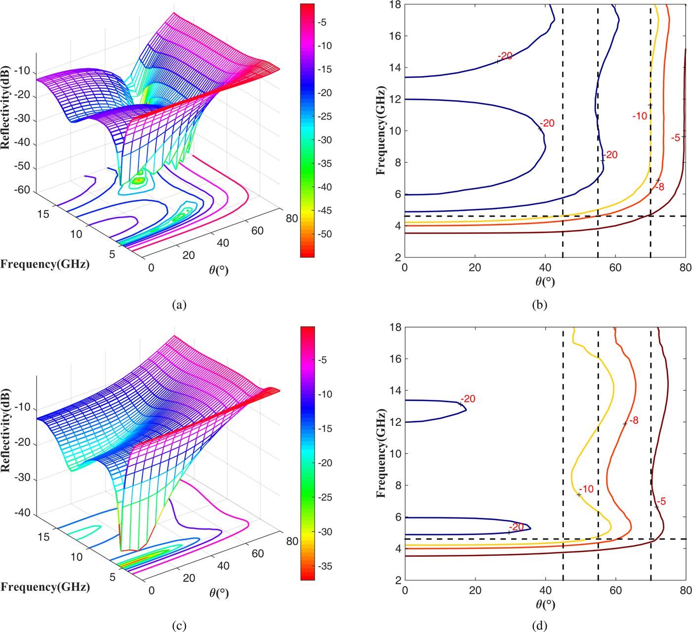
To better demonstrate the wide-band and wide-angle properties of this graded design, the 3D plots and contour plots (in dB unit) of the optimized reflectivity are illustrated in Figs 3(a) and 3(b) for TM polarization, and Figs 3(c) and 3(d) for TE polarization. As seen from the curves in the figure, for both TE and TM polarization, the fractional bandwidth of more than 118.6%, i.e., the range of 4.6–18 GHz, is achieved for at least a 10 dB reflectivity reduction when the incident angle is <45°, an 8 dB reduction when the incident angle is <55°, and a 5 dB reduction when the incident angle is <70°. Meanwhile the 10 dB reduction upper angle limit is approximately 25° and 30° for the uniform coating hexagonal and overexpanded honeycomb RASs in [Reference Feng, Zhang, Wang and Fan29] and [Reference Wang, Zhang, Chen, Zhou, Jin and Fan30], which lose their absorbing ability when the incident angle is larger than 55°. In addition, the total thickness is 10.7 and 30 mm for our graded design and the uniform design in the literature, which indicates that the graded coating is a better choice for the ultra-thin honeycomb RAS. A more detailed comparison between our design and the theoretical limitation will be discussed in the next section.

Fig. 3. Reflectivity of the optimized graded honeycomb RAS.
Verification and comparisons
Verification
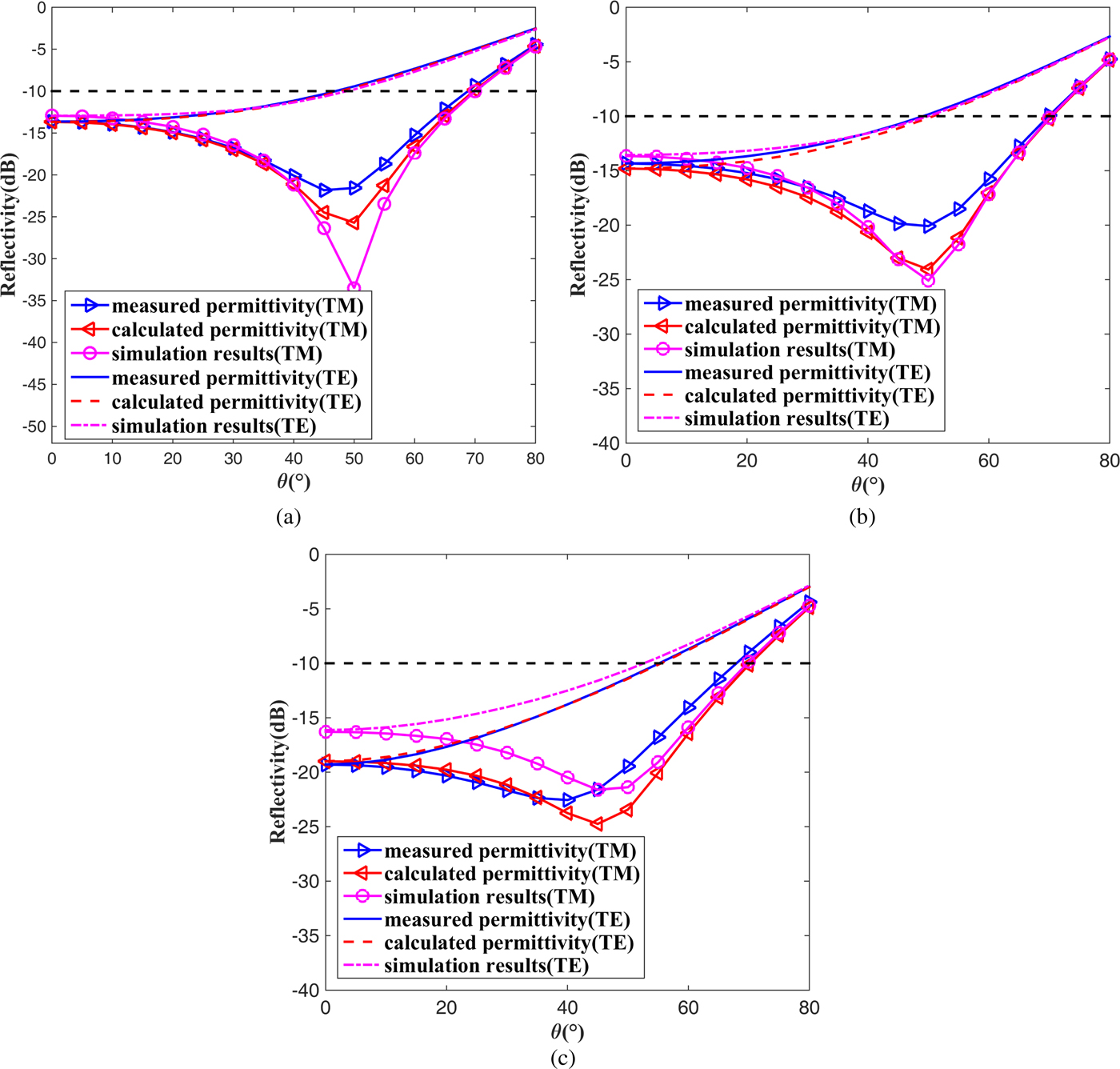
The measured effective permittivity (available in the range of 8–12 GHz), the dispersive effective permittivity formula, and the commercial full-wave simulation software are utilized to further demonstrate the validity of our optimization, as shown in Fig. 4.

Fig. 4. Validity of our optimization.
According to the figure, the reflectivity curves obtained by the calculated, simulated, and measured data are in good agreement with each other. This proves the correctness of our design.
Comparisons
Although our design has better oblique incident performance than the honeycombs in the literature, the optimization process itself does not provide any criterion for evaluating how good the resulting design is. Hence, the theoretical limitation for creating broad-band non-magnetic absorbers should be derived to further evaluate the presented honeycomb RAS.
Since the considered honeycomb absorbers are constructed from non-magnetic, linear, passive, and time-invariant materials, the limitations for ΓTE and ΓTM, i.e., the reflection coefficients for TE and TM polarization, are given by [Reference Doane, Sertel and Volakis34]
 $$\int_0^\infty {\omega ^{-2}\log \left \vert {\displaystyle{1 \over {\Gamma_{TE}\lpar {\,j\omega} \rpar }}} \right \vert} d\omega \le \displaystyle{{\pi d\cos \theta} \over c},$$
 $$\int_0^\infty {\omega ^{-2}\log \left \vert {\displaystyle{1 \over {\Gamma_{TM}\lpar {\,j\omega} \rpar }}} \right \vert} d\omega \le \displaystyle{{\pi d} \over {c\cos \theta}}, $$
where d is the total thickness of the honeycomb RAS, j is the square root of −1, and c is the speed of light in a vacuum. The inequalities (6a) and (6b) establish the fundamental limits for the performance of any physically realizable passive absorber backed by a ground plane. Notably, they are simple expressions involving the total thickness and incident angle.
In the absorption band, the reflection coefficient is designed to be less than a desired value Γ0, for instance, 0.1, 0.158, and 0.316 for at least 10, 8, and 5 dB reflectivity reductions, respectively. Therefore, a piecewise linear approximation of the frequency response can be a simple candidate to evaluate the theoretical limitation. In this way, the desired reflection coefficient can be expressed as
 $$\Gamma _p\lpar f \rpar = \left\{ {\matrix{ {\Gamma_0} \cr 0 \cr}} \right.{\kern 1pt} {\kern 1pt} {\kern 1pt} {\kern 1pt} {\kern 1pt} {\kern 1pt} {\kern 1pt} {\kern 1pt} {\kern 1pt} {\kern 1pt} \matrix{ {\,f_{\min} \lt f \lt f_{\max}} \cr {else} \cr}, $$
where p stands for the polarization, i.e., TE or TM, and f max and f min are the upper and lower frequency limit of the absorption band, respectively.
Tables 1 and 2 display the detailed compassion between our design and the reported uniform coating honeycomb RAS in [Reference Feng, Zhang, Wang and Fan29] and [Reference Wang, Zhang, Chen, Zhou, Jin and Fan30]. It can be found that the total thickness of our design is only approximately 1.29 times of the theoretical limitation. Compared with the results in the literature, the thickness in term of the wavelength at the lowest cut-off frequency d/λ max is decreased by 59%, the thickness to bandwidth ratio (λ max − λ min)/d is increased by 134%, and the angular stability range is increased by 50, 44, and 55% for at least 10, 8, and 5 dB reflectivity reductions, respectively.
Table 1. Wide-band property comparison with [Reference Feng, Zhang, Wang and Fan29] and [Reference Wang, Zhang, Chen, Zhou, Jin and Fan30] (at least 10 dB reflectivity reduction)

Table 2. Wide-angle property comparison with [Reference Feng, Zhang, Wang and Fan29] and [Reference Wang, Zhang, Chen, Zhou, Jin and Fan30] (at least 10, 8, and 5 dB reflectivity reductions)

Furthermore, the optimization results for different coating techniques, which are obtained by using the same optimization variables and settings, are compared in Table 3. The total thickness of uniform honeycomb RAS is more than two times that of the graded coating honeycomb. The best objective value is 0.543 for the graded coating and 0.465 for the uniform coating. Meanwhile, to achieve the same angular stability, i.e., at least 10, 8, and 5 dB reflectivity reductions in the ranges of 0–45°, 0–55°, and 0–70°, respectively, the absorption bandwidth decreases from 13.4 to 11.1 GHz. In addition, although the absorption in the S-band (2–4 GHz) benefits from its large thickness, the uniform coating structure still suffers from an undesired operation band gap in the range of 3.4–8.0 GHz, as illustrated in Fig. 5.
Fig. 5. Uniform coating optimization results.
Table 3. Comparison between graded and uniform coating

Finally, the presented honeycomb RAS will be further evaluated by comparison with our pervious graded coating design in [Reference Zhao, Liu, Song and Xi33]. The 10 dB reflectivity reduction contour lines are displayed in Figs 6(a) and 6(b). The presented honeycomb RAS has better angular stability and polarization-independence property, but its bandwidth is less than the previous design. Because the selection of the objective function is the main difference between these two works, it indicates that the normal incident objective function itself can only provide good absorption for the TM polarization wave, while the optimization for the TE polarization wave needs an objective function that takes both the bandwidth and incident angle in to account. In addition, as shown in Fig. 6(c), the oblique incident objective value is 0.543 for the presented honeycomb RAS, 0.497 for the graded design in [Reference Zhao, Liu, Song and Xi33], and 0.465 for the uniform coating. Obviously, on the one hand, one can obtain the best solution when the oblique incident objective function and graded coating are used together. On the other hand, the combination of the graded coating and normal incident objective function can provide better result than the uniform coating approach combined with the oblique incident objective function. This means that both the objective function and the coating technique are of importance for the design of the honeycomb RAS with wide-band and wide-angle properties, but a smart coating strategy plays a greater role than a good objective function.
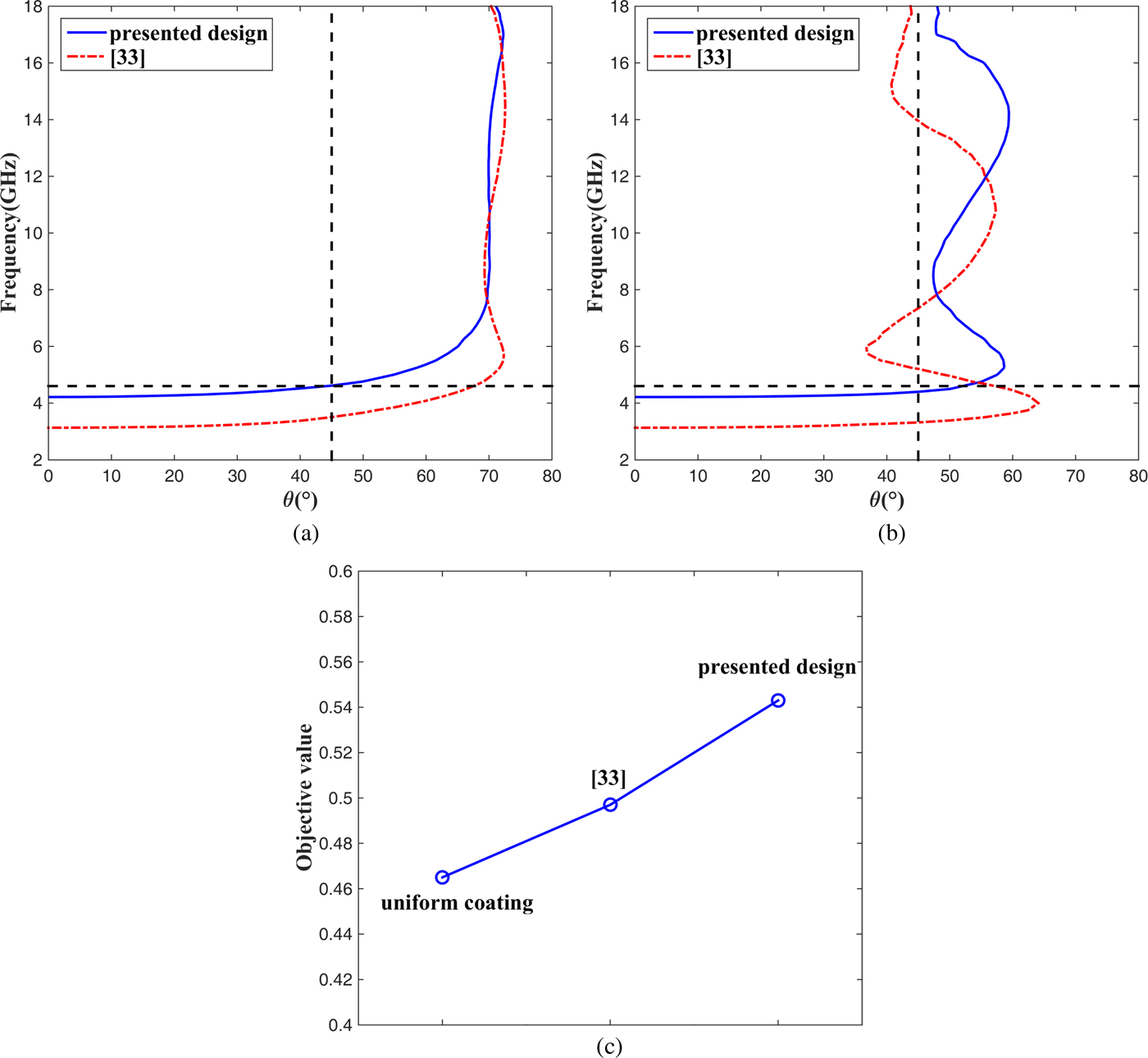
Fig. 6. Comparison with [Reference Zhao, Liu, Song and Xi33].
Conclusion
In summary, we present a coating thickness optimization of the graded honeycomb RAS for the wide-band and wide-angle application. The fractional bandwidth of more than 118.6% is achieved for at least a 10 dB reflectivity reduction when the incident angle is <45°, an 8 dB reduction when the incident angle is <55°, and a 5 dB reduction when the incident angle is <70°. The optimized solution is much better than the available results in the literature and the good agreement between the calculated, simulated, and measured data demonstrates the validity of our optimization. Finally, a detailed comparison shows that the selection of the coating technique, rather than the choice of the objective function, can improve the performance of the honeycomb RAS more effectively.
Acknowledgement
This work was partly supported by the National Natural Science Foundation of China under project numbers 61501369, 21706208, and 51773167, the Postdoctoral Foundation of China under project number 2016M592904XB, the Shaanxi Province Natural Science Foundation Research Project under project number 2017JM6081, the Young Talent fund of University Association for Science and Technology in Shaanxi China under project number 20170110, the Postdoctoral Research Project of Shaanxi Province under project number No.2016BSHEDZZ36, Xi'an Science and Technology Plan Project under project number 2017080CG/RC043(XALG013), and the Foundation of Xi'an University of Technology under project numbers 105-211423, 2016CX040, 310-252051618.
 Yuchen Zhao received the B.S., M.S., and Ph.D. degrees in Electronic Science and Technology from Northwestern Polytechnical University, Xi'an, China, in 2007, 2010, and 2014, respectively. He joined the faculty of Electronic Engineering Department, Xi'an University of Technology, in 2014. His research interests include antenna and wave propagation.
 Fang Ren received her diploma in 2010 from the Xi'an University of Technology and received her Ph.D. degree in Chemistry at the Northwestern Polytechnical University in 2015. Her main research interest is electromagnetic shielding.
 Li He was born in Shaanxi, China. He received the doctorate in Electronic Science and Technology from Xi'an Jiaotong University, Xi'an, China, 2015. He became a full-time teacher in Xi'an University of Technology in 2015, Xi'an, China. His main research interests are electromagnetic absorption materials.
 Jinsheng Zhang received the M.S. and Ph.D. degrees in Navigation, Guidance, and Control from the Xi'an Research Institute of Hi-tech, Xi'an, China, in 2005 and 2009. In 2009, he joined the control faculty of the Xi'an Research Institute of Hi-tech, Xi'an, China, where he founded the geomagnetic matching navigation research team in 2004. He currently works as an engineer and his recent research interests include geomagnetic matching navigation, simulation and evaluation, and wave propagation.
 Yanning Yuan received the B.S. degree in Electronic Information from Liaoning Shihua University, Fushun, China, in 2004, M.S. degree in Communicating Engineering from Xi'an University of Technology, Xi'an, China, in 2007. She joined the Shaanxi Lingyun Science and Technology Co., Ltd. and served as a project manager subsequently. She is currently a full-time research worker at the Xi'an University of Technology. Her research interests include ultra-wideband antennas, multi-frequency antenna, and RF circuit.
 Xiaoli Xi received the B.S degree in Applied Physics from the University of Defense Technology, Changsha, China, in 1990. M.S degree in Biomedical Engineering from Fourth Military Medical University, Xi'an, China, in 1998, and Ph.D. degree in Electrical Engineering from Xi'an Jiaotong University, Xi'an, China, in 2004. She is currently a Professor at the Department of Electric Engineering, Xi'an University of Technology, Xi'an, China. Her recent research interests include wave propagation, antenna design, and communication signal processing.