


1. Introduction
Fish and birds are known to benefit from ‘steady ground effect’, where lift forces are amplified near a seafloor or water surface. Trout, mandarin fish, gulls and pelicans all use this effect to swim/fly more efficiently (Baudinette & Schmidt-Nielsen Reference Baudinette and Schmidt-Nielsen1974; Blake Reference Blake1979; Hainsworth Reference Hainsworth1988; Webb Reference Webb1993). When fins/wings oscillate near a boundary, they experience ‘unsteady ground effect’, which can boost thrust as well as lift. Pitching hydrofoils can boost thrust and speed by up to  $45\,\%$ and
  $25\,\%$, respectively, with no loss in efficiency, by swimming near the ground (Quinn, Lauder & Smits Reference Quinn, Lauder and Smits2014a; Quinn et al. Reference Quinn, Moored, Dewey and Smits2014b; Fernández-Prats et al. Reference Fernández-Prats, Raspa, Thiria, Huera-Huarte and Godoy-Diana2015; Mivehchi, Dahl & Licht Reference Mivehchi, Dahl and Licht2016). Low-Reynolds-number simulations produce similar trends (Dai, He & Zhang Reference Dai, He and Zhang2016; Tang et al. Reference Tang, Huang, Gao and Lu2016; Park, Kim & Sunga Reference Park, Kim and Sunga2017; Zhang, Huang & Lu Reference Zhang, Huang and Lu2017).
Unsteady ground effect is governed by phenomena that are absent in steady flows near the ground. Oscillating near the ground produces asymmetric vortex streets, return flows and vortex compression (Quinn et al. Reference Quinn, Lauder and Smits2014a; Fernández-Prats et al. Reference Fernández-Prats, Raspa, Thiria, Huera-Huarte and Godoy-Diana2015). Near-ground oscillations also cause asymmetric lift forces. Even neutrally buoyant swimmers with symmetric kinematics experience regions of net downward lift and net upward lift, creating altitudes to which oscillating hydrofoils naturally converge. These equilibria, which have been observed in inviscid simulations and two-dimensional hydrofoil experiments, result from a balance between time-averaged circulatory forces and added mass forces (Kurt et al. Reference Kurt, Cochran-Carney, Zhong, Mivehchi, Quinn and Moored2019).
Previous studies of unsteady ground effect have considered single aspect ratios. It is therefore unknown how aspect ratio affects the wakes, thrust and equilibrium altitudes of near-boundary swimmers and flyers. Biological observations suggest that it may be a critical design parameter. Benthic (bottom-dwelling) rays tend to have lower-aspect-ratio rounded pectoral fins, whereas pelagic (non-bottom-dwelling) rays have higher-aspect-ratio triangular fins (Rosenberger Reference Rosenberger2001). Changes in morphology as fish evolve to benthic lifestyles is, in fact, one of the ‘most common patterns of evolution among aquatic animals’ (Cooper et al. Reference Cooper, Carter, Conith, Rice and Westneat2017).
To explore the effects of aspect ratio on neutrally buoyant swimmers, we set out to answer three questions. (1) Does aspect ratio affect near-boundary thrust and efficiency? (2) Does aspect ratio affect the existence and/or position of equilibrium altitudes? (3) Does aspect ratio affect the evolution of the three-dimensional asymmetric wakes behind near-boundary propulsors? We answered these questions through a combination of direct force measurements, potential flow simulations and three-dimensional particle image velocimetry (PIV).
2. Methods
2.1. Measuring near-ground thrust and efficiency
To study aspect ratio, we tested hydrofoils with the same chord ( $c = 95$ mm) and four aspect ratios: 1, 1.5, 2 and 2.5 (figure 1a,b). The hydrofoils had a tear-drop cross-section and were 3D-printed with solid ABS. A stainless-steel driveshaft (
 $6.35$ mm diameter) pitched the hydrofoil at its leading edge, i.e. pitch angle
  $\theta$ was prescribed as
  $\theta _0 \sin (2{\rm \pi} f t)$, where
  $\theta _0$ is pitch amplitude,
  $f$ is frequency and
  $t$ is time. The driveshaft was driven by a high-torque digital servo motor (Dynamixel MX64), and its angle was verified by an absolute encoder (US Digital A2K 4096 CPR).

Figure 1. Experimental set-up. (a) Four different aspect ratios (![]() ) were tested. (b) The foils underwent pitch oscillations near a splitter plane (pitch amplitude
) were tested. (b) The foils underwent pitch oscillations near a splitter plane (pitch amplitude  $\theta _0$, ground proximity
  $d$, incoming flow speed,
  $u$). (c) A
  $z$-traverse raised and lowered the foils in a water channel to facilitate PIV. A baffle plane reduced the effect of surface waves. Insert: an automated
  $y$-traverse (‘fisherman system’) controlled ground proximity by using a detachable latch to shift the lateral position of the foil (
 ${\pm }0.01$ mm resolution).
To test their near-ground performance, we pitched the hydrofoils near a vertical splitter plate in a closed-loop water channel (Rolling Hills 1520, test section  $380 \times 450 \times 1520$ mm,
  $W \times H \times L$) (figure 1c). The splitter plate was used instead of the sidewall to control the boundary-layer thickness. A boundary-layer thickness of
  $\delta _\mathrm {99\,\%} \approx 7.5$ mm was measured using PIV at the position aligned with the leading edge of the hydrofoil. The incoming flow speed
  $u$ was set to 143 mm s
 $^{-1}$ using an ultrasonic flowmeter (Dynasonics Series TFXB). This speed gave a chord-based Reynolds number of
  $13\ 500$ (comparable with Blevins & Lauder (Reference Blevins and Lauder2013), for example, who tested a ray-inspired robot at
  $Re\approx 10\,000$). The distance between the foil's leading edge and the splitter plate,
  $d$, was controlled by an automated lateral traverse (figure 1(c) insert).
We tested each hydrofoil over a range of kinematics and ground proximities. For each hydrofoil, we considered eight Strouhal numbers ( $St \equiv 2fc \sin \theta _0/u$) between 0.2 and 0.55, five pitching amplitudes (
 $\theta _0$) between
  $7^{\circ }$ and
  $15^{\circ }$ and 17 dimensionless ground proximities (
 $d/c$) between 0.24 and 1.66. Combinations of
  $St$,
$St$,  $\theta _0$ and
  $d/c$ that would produce
  $f \geq 2.5$ Hz or less than
  $10$ mm (1.3
  $\delta _\mathrm {99\,\%}$) distance between the trailing edge and the ground were omitted. Each trial was repeated three times. We measured forces with a six-axis force–torque sensor (ATI-Mini 40: SI-40-2 for
 ![]() , SI-20-1 for
, SI-20-1 for ![]() ), then time-averaged streamwise and lateral forces (over 20 cycles) to produce ‘net thrust’
), then time-averaged streamwise and lateral forces (over 20 cycles) to produce ‘net thrust’  $\bar {T}$ and ‘net lift’
  $\bar {L}$. We also measured the propulsive efficiency, defined as
  $\eta \equiv \bar {T} u / \overline {\tau _z \dot {\theta }}$, where
  $\overline {\tau _z \dot {\theta }}$ is the time-averaged power based on the pitching torque (
 $\tau _z$) and pitching velocity (
 $\dot {\theta }$). See Ayancik et al. (Reference Ayancik, Zhong, Quinn, Brandes, Bart-Smith and Moored2019) for a validation of our system based on prior work.
2.2. Measuring three-dimensional flow fields
To explore the hydrodynamic interactions between the hydrofoil and the ground, we used layered stereo particle image velocimetry (SPIV) to generate three-dimensional flow fields. To capture the layers, we kept the laser sheet stationary while raising/lowering the hydrofoil with the automated  $z$-traverse (
 $\pm$2.5
  $\mathrm {\mu }$m resolution; see Zhong, Dong & Quinn (Reference Zhong, Dong and Quinn2019) for details). The layers started at the midspan and ended
  $10$ mm beneath the foil, with
  $5$ mm between each layer. Owing to the symmetry of the hydrofoil, we mirrored the bottom layers in order to estimate the upper layers. The flow was seeded with neutrally buoyant polyamide particles (
 $12\ \mathrm {\mu }$m average diameter), which were illuminated by two overlapping laser sheets (5 W Raypower MGL-W-532 and 10 W CNI MGL-W-532A). The lasers were fired from opposite sides to avoid a hydrofoil shadow. Two cameras beneath the channel recorded
  $2956\times 1877$ pixel images of the particle motions (Phantom, SpeedSense M341).
To isolate the key features of the flow fields, we phase-averaged the PIV data. We averaged 600 frames over 15 pitching cycles in order to obtain 40 phase-averaged frames. A custom trigger synced the camera shutter with the encoder data to ensure a consistent starting phase. Cross-correlations were calculated by an adaptive PIV algorithm (Dantec Dynamic Studio 6.1) with  $16\times 16$ px overlapping interrogation windows, and the phase-averaging, layer stitching and vorticity calculations were done in Matlab (2019). Flow-field plots and animations were produced in Tecplot (2017R2).
2.3. Simulating near-ground propulsion
To determine whether viscous effects played a significant role in our experiments, we ran potential flow simulations at overlapping conditions. The simulations had three purposes: (1) provide additional evidence for trends observed in the experiments, (2) determine which (if any) trends are sensitive to viscous effects and (3) confirm that the boundary layer on the splitter plate (which does not exist in near-ground free-swimming/flying) has a negligible effect. The simulations use an unsteady three-dimensional boundary-element method that assumes irrotational, incompressible and inviscid flow. The method of images is used to model the presence of the ground (Katz Reference Katz1985). The boundaries of the water channel were simulated based on the test section of the experiments for a fairer comparison. Equilibrium altitudes were determined by iterating  $d/c$ values until time-averaged lateral forces converged below a threshold range (
 $|{C_L}| \leq 0.015$).
The workflow of the simulations is described in our previous work (Moored Reference Moored2018; Ayancik et al. Reference Ayancik, Zhong, Quinn, Brandes, Bart-Smith and Moored2019), and a brief summary is given here. Potential flow is governed by Laplace's equation,  $\nabla ^{2}\phi '=0$, where
  $\phi '$ is the perturbation potential in an inertial frame fixed to the undisturbed fluid. To approximate a solution for
  $\phi '$, the hydrofoil's surface, wall of the water channel and the wake are modelled as discrete quadrilateral boundary elements. Each element contains a constant-strength doublet and source, and at each timestep, new wake elements are shed at the hydrofoil's trailing edge. Wake elements advect with the local velocity based on a desingularised Biot–Savart law, as in Krasny (Reference Krasny1986), Zhu et al. (Reference Zhu, Wolfgang, Yue and Triantafyllou2002) and Moored (Reference Moored2018). The evolving distribution of doublet/source strengths is determined by the Kutta condition (smooth flow at the trailing edge), Kelvin's circulation theorem (constant global circulation), and the no-flux boundary condition (
 $\boldsymbol {\nabla } \phi '\boldsymbol {\cdot } n_i=0$, where
  $n_i$ is the normal vector of the
  $i$th surface element). Once
  $\phi '$ is known, the forces on the hydrofoil follow from the unsteady Bernoulli equation.
3. Results
3.1. Near-ground performance of high-aspect-ratio hydrofoils
The highest-aspect-ratio foil we considered (![]() ) shows similar trends as two-dimensional near-ground hydrofoils in previous studies. As expected, the time-averaged thrust is highest at high Strouhal numbers and low ground distances (figure 2a). As the foil moves away from the ground, thrust decreases and levels off, generally following the empirical scaling observed by Quinn et al. (Reference Quinn, Lauder and Smits2014a) (
) shows similar trends as two-dimensional near-ground hydrofoils in previous studies. As expected, the time-averaged thrust is highest at high Strouhal numbers and low ground distances (figure 2a). As the foil moves away from the ground, thrust decreases and levels off, generally following the empirical scaling observed by Quinn et al. (Reference Quinn, Lauder and Smits2014a) ( $\bar {T}\sim c_1[1+(d/c)^{-0.4}]St^2$,
  $R^2 = 0.97$) and the model-based scaling proposed by Mivehchi et al. (Reference Mivehchi, Zhang, Kurt, Quinn and Moored2020) (
 $\bar {T}\sim [c_1 +c_2(d/c)^{-2}]St^2$,
  $R^2 = 0.98$). Unlike thrust, efficiency peaks at an intermediate Strouhal number and has only modest increases near the ground (
 $+1$–
$+1$– $3\,\%$; figure 2b). The implication is that for the same input kinematics, a hydrofoil can produce higher free-swimming speeds and accelerations near the ground without sacrificing efficiency.

Figure 2. Performance coefficients for ![]() 2.5 at
2.5 at  $\theta _0 = 9^\circ$. (a) Thrust coefficient (
 $C_\mathrm {T}\equiv \bar {T}/(0.5 \rho u^2 sc$) peaks at high Strouhal numbers (
 $St$) and low ground distances (
 $d/c$). (b) Efficiency (
 $\eta$) peaks at intermediate
  $St$ and shows little dependence on
  $d/c$. (c) Lift coefficient (
 $C_{L}\equiv \bar {L}/(0.5 \rho u^2 sc$) can be positive or negative, leading to equilibrium altitudes where
  $C_{L}=0$.
The ![]() hydrofoil also reproduces the equilibrium altitudes that others (Kurt et al. Reference Kurt, Cochran-Carney, Zhong, Mivehchi, Quinn and Moored2019) have observed. Far from the ground, lift is negative; closer to the ground, lift becomes positive (figure 2c). Between these two lift regimes is a stable equilibrium altitude into which an untethered, open-loop, symmetrically actuated hydrofoil would settle. As
hydrofoil also reproduces the equilibrium altitudes that others (Kurt et al. Reference Kurt, Cochran-Carney, Zhong, Mivehchi, Quinn and Moored2019) have observed. Far from the ground, lift is negative; closer to the ground, lift becomes positive (figure 2c). Between these two lift regimes is a stable equilibrium altitude into which an untethered, open-loop, symmetrically actuated hydrofoil would settle. As  $St$ increases, the positive lift magnitudes are amplified, leading to a more stable and higher equilibrium altitude (
 $d/c$ rises from 0.55 to 0.85 as
  $St$ rises from 0.2 to 0.5). This positive shift with
  $St$ is consistent with previous work on two-dimensional foils (Kurt et al. Reference Kurt, Cochran-Carney, Zhong, Mivehchi, Quinn and Moored2019) and confirms that equilibrium altitudes exist for finite aspect ratios.
We also observed a second set of equilibrium altitudes very close to the ground ( $d/c< 0.35$; figure 2c). Unlike the lift near the stable equilibria, the lift here is increasing with
  $d/c$. Just above equilibrium, positive lift pushes the hydrofoil away from the ground; just below equilibrium, negative lift sucks the hydrofoil towards the ground. The result is an unstable equilibrium. The instability is considerable; lift changes rapidly (
 ${\rm \Delta} C_L \approx 1$) over a narrow range (
 ${\rm \Delta} d/c \approx 0.1$;
  ${\rm \Delta} d \approx 10$ mm). Unstable near-ground equilibria have been hypothesised (Kurt et al. Reference Kurt, Cochran-Carney, Zhong, Mivehchi, Quinn and Moored2019), but here they are shown experimentally for the first time. The effect only appears at high Strouhal numbers (
 $St \geq 0.4$) and low
  $d/c$ values, which helps to explain why they are difficult to observe.
Pitching amplitude also affects performance near the ground. At low Strouhal numbers, smaller amplitudes lead to higher net thrust, presumably because of the smaller projected area ( $cs\sin \theta _0$; figure 3a). At high Strouhal numbers, amplitude has relative smaller effect on absolute thrust but does affect near-ground thrust enhancement (
 ${\rm \Delta} C_T = 0.58$ for
  $\theta _0 = 9^\circ$ vs.
  ${\rm \Delta} C_T = 0.35$ for
  $\theta _0 = 15^\circ$ at
  $St = 0.5$). Following thrust, efficiency was also higher at lower amplitudes (figure 3b). For example, at a representative case far from the ground (
 $St = 0.3$;
  $d/c = 1.66$), efficiency was
  $6.0\,\%$ for
  $\theta _0 = 15^\circ$ versus
  $\eta = 18.7\,\%$ for
  $\theta _0 = 9^\circ$. Moreover, the equilibrium altitude decreased from
  $0.93$ to
  $0.82$ at lower amplitudes (
 $\theta _0 = 15^\circ$ to
  $\theta _0 = 9^\circ$; figure 3c).

Figure 3. Performance coefficients for ![]() , 1.5, 2 and 2.5. (a,c) Thrust coefficient (a) and efficiency (c) show similar trends as aspect ratio decreases, with a slight decrease at higher pitch amplitudes and lower aspect ratios. (e) Lift coefficient (
, 1.5, 2 and 2.5. (a,c) Thrust coefficient (a) and efficiency (c) show similar trends as aspect ratio decreases, with a slight decrease at higher pitch amplitudes and lower aspect ratios. (e) Lift coefficient ( $C_{L}$) shows changing trends as aspect ratio decreases: positive lift values and equilibrium altitudes decrease in magnitude. (b,d,f) The performance coefficients for each
  $d/c$ and
 ![]() combination, averaged across all
combination, averaged across all  $St$ and
  $\theta _0$ cases, reveal the dominant effects of changing aspect ratio. Ground proximities with only partial amplitudes were omitted in bulk averaging to make fair comparisons.
3.2. Near-ground performance of low-aspect-ratio hydrofoils
In general, we found that as aspect ratio decreases, so do the effects of the ground. For example, in otherwise identical conditions ( $d/c = 0.35$,
  $St = 0.55$,
  $\theta _0 = 15^{\circ }$), the
 ![]() hydrofoil's thrust was boosted by
hydrofoil's thrust was boosted by  $+41\,\% \pm 1\,\%$, compared with only
  $+18\,\% \pm 3\,\%$ when
 ![]() (figure 3a). To consider the bulk performance of each aspect ratio, we averaged the thrust boosts across all sets of kinematics for each aspect ratio. On average, the ground amplified thrust more than twice as much when
(figure 3a). To consider the bulk performance of each aspect ratio, we averaged the thrust boosts across all sets of kinematics for each aspect ratio. On average, the ground amplified thrust more than twice as much when ![]() than it did when
than it did when ![]() (figure 3b). The regime where thrust was amplified (
(figure 3b). The regime where thrust was amplified ( $d/c\lesssim 0.75$) was similar across the four aspect ratios.
The ground's effect on efficiency was less sensitive to aspect ratio (figure 3c,d). Lower aspect ratios led to lower efficiencies, presumably due to tip vortices and induced drag (see e.g. Shao et al. Reference Shao, Pan, Deng and Yu2010). However, the effect of ground proximity was similar across all aspect ratios. Efficiency stayed mostly constant, with a  $1$–
$1$– $3\,\%$ rise near the ground (
 $d/c\lesssim 0.5$). (Figure 3d).
Unlike thrust and efficiency, the lift, and therefore the equilibrium altitude, is significantly affected by aspect ratio (figure 3e,f). As the aspect ratio decreases, the near-ground regime of positive lift shrinks, and the equilibrium altitude shifts toward the ground (average equilibrium  $d/c$ drops from 0.8 to 0.35, figure 3f). When
 ![]() , the positive lift regime is so small that the equilibrium altitude vanishes at low Strouhal numbers, though it persists when
, the positive lift regime is so small that the equilibrium altitude vanishes at low Strouhal numbers, though it persists when  $St \geq 0.35$.
The second unstable equilibrium altitude is less sensitive to aspect ratio. Because the equilibria occur over a small band of high Strouhal numbers and very close to the ground, they do not appear in averaged lift trends (figure 3f). To better understand the unstable equilibria, we therefore plotted  $C_L$ near the ground at a high Strouhal number (figure 4a). The unstable equilibria are mostly unaffected by aspect ratio, varying over only a narrow range (
 $d/c = 0.28 \sim 0.3$). The unstable equilibria shift slightly higher with increasing amplitude and Strouhal number (figure 3b,c), but differences due to aspect ratio remain small. Note that the unstable equilibria start to disappear at high aspect ratio and high amplitude (figure 4b).

Figure 4. Near-ground unsteady equilibria are less sensitive to aspect ratio than stable equilibria. (a) Aspect ratio affects the location and magnitude of maximum lift, but it has little effect on the unsteady equilibrium altitude. (b) For a fixed Strouhal number, the unsteady equilibrium altitude slightly increases with larger amplitude. (c) For a fixed amplitude, the unsteady equilibrium altitude slightly increases with larger Strouhal number.
3.3. Comparing simulations and experiments
Comparing potential flow simulations with our experiments confirms that viscosity probably plays a minor role in unsteady ground effects at high Reynolds numbers and moderate Strouhal numbers ( $St=0.25,0.35$). As in the experiments, the simulations show that lower aspect ratios lead to weaker lift forces and lower equilibrium altitudes (figure 5a). In both cases, the equilibrium altitude drops by
  $\approx$0.2 chord lengths as
 ![]() falls from 2.5 to 1.5. In addition, similarly to the experiments, the simulations predict a vanishing equilibrium as aspect ratio approaches 1 at low Strouhal numbers (
falls from 2.5 to 1.5. In addition, similarly to the experiments, the simulations predict a vanishing equilibrium as aspect ratio approaches 1 at low Strouhal numbers (![]() , figure 5a). We also performed simulations at high Strouhal number (
, figure 5a). We also performed simulations at high Strouhal number ( $St = 0.5$,
  $\theta _0 = 9^\circ$) close to the ground to explore the unstable equilibria. The simulations reproduced unstable equilibria at high aspect ratios (
 $d/c = 0.274$ for
 ![]() ;
;  $d/c = 0.287$ for
 ![]() ) but not low aspect ratios (
) but not low aspect ratios (![]() ).
).

Figure 5. Comparison between experiment and potential flow simulation. (a) Both experiments and simulations show that stable equilibrium altitude increases with aspect ratio. No equilibria were found for the lowest-aspect-ratio cases at the Strouhal numbers of the simulations (0.25 and 0.35). (b) Relative change of time-averaged thrust coefficients ( ${\rm \Delta} C_T$) at
  $St = 0.35$,
  $\theta _0 = 15^\circ$. (c) Relative change of time-averaged efficiency (
 ${\rm \Delta} \eta$) at
  $St = 0.35$,
  $\theta _0 = 15^\circ$.
Our potential flow simulations also predict a rise in thrust near the ground, as they have previously (Quinn et al. Reference Quinn, Moored, Dewey and Smits2014b). As in the experiments, the simulations predict that higher-aspect-ratio foils experience a larger boost in thrust near the ground ( ${\rm \Delta} C_T = 0.14$ at
 ![]() versus
versus  ${\rm \Delta} C_T = 0.046$ at
 ![]() ) (figure 5b). However, the absolute thrust coefficient was consistently overestimated by the simulations (by about
) (figure 5b). However, the absolute thrust coefficient was consistently overestimated by the simulations (by about  $0.21$–
 $0.25$ for each aspect ratio). The discrepancy is presumably due to the absence of skin-friction drag and leading-edge separation in the simulations.
Efficiency trends show similar patterns as thrust trends. The efficiency in the simulations stays mostly constant, then increases by  $3\,\%$–
 $5\,\%$ when
  $d/c\leq 0.5$ (figure 5c). Because the simulations overpredict absolute thrust, they also overpredict efficiency (
 $\eta \equiv \bar {T} u / \overline {\tau _z \dot {\theta }}$). As in previous work (Quinn et al. Reference Quinn, Lauder and Smits2014a), the simulations underestimate power input to the fluid (at least at
  $St = 0.35$), which further increases the absolute efficiency magnitude. Nevertheless, simulations and experiments predict comparable relative changes in efficiency (
 ${\rm \Delta} \eta = 1$–
 $5\,\%$) as the foil approaches the ground.
3.4. Near-ground wakes of high- and low-aspect-ratio foils
To explore how the aspect ratio affects the near-ground wake, we measured the flow around two hydrofoils (![]() and
and ![]() ) in and out of ground effect (
) in and out of ground effect ( $d/c=0.5$ and
  $d/c=1.8$). Far from the ground, the higher-aspect-ratio foil sheds a 2S reverse von Kaŕmań vortex street at its midspan (figure 6a). This classic midspan wake has been observed in several previous studies, e.g. the soap-film visualisations of Schnipper, Andersen & Bohr (Reference Schnipper, Andersen and Bohr2009). Here we show how this 2S wake fits into the full three-dimensional wake behind the foil. At each half-cycle, streamwise tip vortices and a spanwise trailing-edge vortex are shed as a loop. As the loop advects into the wake, its downstream end wraps around the upstream end of the previous loop, forming one of the spanwise vorticity cores of the 2S wake (vortex 2 in figure 6a). Similarly interconnected loops have been seen behind trapezoidal panels at comparable Reynolds numbers (King, Kumar & Green Reference King, Kumar and Green2018), rectangular foils at low Reynolds numbers (Von Ellenrieder, Parker & Soria (Reference Von Ellenrieder, Parker and Soria2003)
  $Re=164$; Buchholz & Smits (Reference Buchholz and Smits2008)
  $Re=640$) and simulations of rectangular and elliptical foils (Dong, Mittal & Najjar Reference Dong, Mittal and Najjar2006; Shao et al. Reference Shao, Pan, Deng and Yu2010).

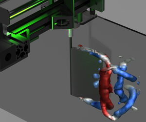
Figure 6. Aspect ratio affects wake topology near the ground. Wakes from experiments (a–d) and simulations (e–h) are shown at the same phase (trailing edge closest to the ground). Wake structures are visualised with iso-surfaces of  $Q$-criterion (
 $Q = 5$ s
 $^{-2}$) coloured by spanwise vorticity (
 $\omega _z$). Sideplots show spanwise vorticity at a midspan slice of the three-dimensional wake. (a,b) Experiments:
 ![]() hydrofoil far from and near to the ground. (c,d) Experiments:
hydrofoil far from and near to the ground. (c,d) Experiments: ![]() hydrofoil far from and near to the ground. (e,f) Simulations:
hydrofoil far from and near to the ground. (e,f) Simulations: ![]() hydrofoil far from and near to the ground. (g,h) Simulations:
hydrofoil far from and near to the ground. (g,h) Simulations: ![]() hydrofoil far from and near to the ground. Supplementary movie 1 is available at https://doi.org/10.1017/jfm.2021.307 for three-dimensional PIV animations.
hydrofoil far from and near to the ground. Supplementary movie 1 is available at https://doi.org/10.1017/jfm.2021.307 for three-dimensional PIV animations.
Near the ground, half of the von Kaŕmań vortices are slowed by the ground, causing the vortex street to clump into vortex pairs that mutually advect upward (figure 6b). These paired vortices were seen behind near-ground two-dimensional pitching foils (Quinn et al. Reference Quinn, Lauder and Smits2014a), and here we show how they fit into a larger three-dimensional wake. Each half-cycle produces a vortex loop, as it does far from the ground. The vortex loop nearer to the ground attaches to, and is slowed by, the ground, creating an arch of vorticity that interacts with the next vortex loop. As in the free-stream case, the downstream end of the next vortex loop curls and wraps around the previous loop, but now the effect is more pronounced, creating spanwise vortex cores that pair together (vortices 1 and 2 in figure 6b).
Compared with the higher-aspect-ratio hydrofoil, the ![]() foil generates a more complicated wake (figure 6c). A midspan slice shows that where two vortex cores had been for
foil generates a more complicated wake (figure 6c). A midspan slice shows that where two vortex cores had been for ![]() , there are now four cores. The three-dimensional wake reveals the source of the complexity: the tip vortices, which are now almost as prominent as the trailing-edge vortices, create a train of intertwined horseshoe vortices instead of a series of coherent loops. The legs of these horseshoe vortices remain coherent, leading to the extra vortex cores in the midspan slice. These results, particularly the role of streamwise vorticity in driving the horseshoe vortex entanglement, confirm and expand upon the dye visualisations of Buchholz & Smits (Reference Buchholz and Smits2008) (
, there are now four cores. The three-dimensional wake reveals the source of the complexity: the tip vortices, which are now almost as prominent as the trailing-edge vortices, create a train of intertwined horseshoe vortices instead of a series of coherent loops. The legs of these horseshoe vortices remain coherent, leading to the extra vortex cores in the midspan slice. These results, particularly the role of streamwise vorticity in driving the horseshoe vortex entanglement, confirm and expand upon the dye visualisations of Buchholz & Smits (Reference Buchholz and Smits2008) (![]() ,
,  $Re=640$).
Near the ground, the wake of the ![]() hydrofoil was less perturbed than the
hydrofoil was less perturbed than the ![]() hydrofoil (figure 6b,d). This is surprising, because tip vortices play a key role in steady ground effect (Rozhdestvensky Reference Rozhdestvensky2006), so one might expect that the wake of the
hydrofoil (figure 6b,d). This is surprising, because tip vortices play a key role in steady ground effect (Rozhdestvensky Reference Rozhdestvensky2006), so one might expect that the wake of the ![]() foil (where tip vortices are more influential) would be more affected by the ground. However, it appears that because the 2S vortex cores are split (vortex 2 into 2a and 2b; figure 6a,c), only vortex 2a experiences a strong slowing effect from its image vortex. In contrast, vortex 2b follows a similar advection path as it does far from the ground. The three-dimensional plot shows that the near-ground vortex ring does not twist and collapse as it does in the
foil (where tip vortices are more influential) would be more affected by the ground. However, it appears that because the 2S vortex cores are split (vortex 2 into 2a and 2b; figure 6a,c), only vortex 2a experiences a strong slowing effect from its image vortex. In contrast, vortex 2b follows a similar advection path as it does far from the ground. The three-dimensional plot shows that the near-ground vortex ring does not twist and collapse as it does in the ![]() case; instead, the ring expands and dissipates, similar to the expansion seen by Tang et al. (Reference Tang, Huang, Gao and Lu2016) behind a near-ground flexible panel (
case; instead, the ring expands and dissipates, similar to the expansion seen by Tang et al. (Reference Tang, Huang, Gao and Lu2016) behind a near-ground flexible panel (![]() ,
,  $Re = 100$).
Our simulations revealed similar wakes as the experiments, suggesting that the near-ground wake is governed largely by inviscid phenomena (figure 6e–h). A notable exception is the midspan wake behind the ![]() foil, where the distinction between vortices 1b and 2b becomes less clear. Some vortex smearing in the simulations is expected owing to the wake desingularisation. In addition, the simulations only shed wake elements at the trailing edge, so the tip vortices, which play an active role in deforming the experimental wakes, are weaker in the simulations. Nevertheless, the simulations still capture the main trends of the wake, including the weaker vortex pairing in the
foil, where the distinction between vortices 1b and 2b becomes less clear. Some vortex smearing in the simulations is expected owing to the wake desingularisation. In addition, the simulations only shed wake elements at the trailing edge, so the tip vortices, which play an active role in deforming the experimental wakes, are weaker in the simulations. Nevertheless, the simulations still capture the main trends of the wake, including the weaker vortex pairing in the ![]() case.
case.
4. Discussion and conclusion
In general, we found that unsteady ground effect is weaker for lower-aspect-ratio hydrofoils. The average thrust enhancement at  $d/c = 0.35$ was
  $44\,\%$ for
 ![]() compared with
compared with  $18\,\%$ for
 ![]() (figure 3b). This difference is not simply caused by the difference in area; we reran the
(figure 3b). This difference is not simply caused by the difference in area; we reran the ![]() trials with a reduced chord length (0.8
trials with a reduced chord length (0.8 $c$), and thrust enhancements changed by less than 5 %. Lower-aspect-ratio foils also produced less asymmetric lift, causing equilibrium altitudes to weaken and shift toward the ground (figure 3f). The equilibrium for the
 ![]() foil was not even detectable at low enough Strouhal numbers. These results are consistent with the near-ground wakes we observed, where the ground had a smaller effect on the wake of the
foil was not even detectable at low enough Strouhal numbers. These results are consistent with the near-ground wakes we observed, where the ground had a smaller effect on the wake of the ![]() foil. Furthermore, vortex-induced drag is known to be a key contributor to streamwise forces on low-aspect-ratio foils (Raspa et al. Reference Raspa, Ramananarivo, Thiria and Godoy-Diana2014), so ground effect may play a minor role in low-aspect-ratio hydrofoil dynamics at low Strouhal numbers. This effect may help explain the findings of Blevins & Lauder (Reference Blevins and Lauder2013), who found no appreciable performance changes for a stringray-inspired robot (
foil. Furthermore, vortex-induced drag is known to be a key contributor to streamwise forces on low-aspect-ratio foils (Raspa et al. Reference Raspa, Ramananarivo, Thiria and Godoy-Diana2014), so ground effect may play a minor role in low-aspect-ratio hydrofoil dynamics at low Strouhal numbers. This effect may help explain the findings of Blevins & Lauder (Reference Blevins and Lauder2013), who found no appreciable performance changes for a stringray-inspired robot (![]() ) swimming near the ground at
) swimming near the ground at  $St = 0.13$.
By comparing experiments and potential flow simulations, we found that unsteady ground effects are primarily inviscid phenomena over the conditions we tested. for ![]() , our results suggest that viscosity plays only a minor role in determining equilibrium altitude, which extends previous findings on two-dimensional hydrofoils (Kurt et al. Reference Kurt, Cochran-Carney, Zhong, Mivehchi, Quinn and Moored2019). However, viscosity reduces relative thrust and efficiency enhancements near the ground, and its role becomes less clear at lower aspect ratios (
, our results suggest that viscosity plays only a minor role in determining equilibrium altitude, which extends previous findings on two-dimensional hydrofoils (Kurt et al. Reference Kurt, Cochran-Carney, Zhong, Mivehchi, Quinn and Moored2019). However, viscosity reduces relative thrust and efficiency enhancements near the ground, and its role becomes less clear at lower aspect ratios (![]() ). Although potential flow simulations confirmed that equilibrium altitudes decrease and vanish as
). Although potential flow simulations confirmed that equilibrium altitudes decrease and vanish as ![]() decreases, we did observe noticeable differences in wake details owing to the absence of viscosity in the
decreases, we did observe noticeable differences in wake details owing to the absence of viscosity in the ![]() case (figure 6c,d,g,h).
case (figure 6c,d,g,h).
It is worth noting that in potential flow theory, a hydrofoil at a distance  $d$ from a boundary is identical to a hydrofoil at distance
  $2d$ from a second hydrofoil pitching 180
 $^\circ$ out of phase with the first. Thrust, for example, is known to scale similarly for hydrofoils that are near a boundary and hydrofoils that are side by side and out of phase (Dewey et al. Reference Dewey, Quinn, Boschitsch and Smits2014). The inviscid nature of our results therefore suggests that stable and unstable equilibria may also exist for side-by-side swimmers. Indeed, hydrodynamic effects are known to play a key role in the collective behavior of fish (Filella et al. Reference Filella, Nadal, Sire, Kanso and Eloy2018).
The fact that lower aspect ratios cause lower equilibrium altitudes can be explained with known scaling laws of pitching hydrofoils. In the case of two-dimensional near-ground hydrofoils, asymmetric added mass forces decrease the equilibrium altitude, whereas asymmetric circulatory forces increase the equilibrium altitude (Kurt et al. Reference Kurt, Cochran-Carney, Zhong, Mivehchi, Quinn and Moored2019). The former effect can be explained by near-ground added mass coefficients (Brennen Reference Brennen1982), and the latter effect by the image vortex system (Rozhdestvensky Reference Rozhdestvensky2006). In the case of finite-span hydrofoils, added mass and circulatory forces are reduced by factors of ![]() and
and ![]() , respectively (Prandtl Reference Prandtl1920; Brennen Reference Brennen1982), leading to a ratio between the two of
, respectively (Prandtl Reference Prandtl1920; Brennen Reference Brennen1982), leading to a ratio between the two of ![]() . Therefore, as the aspect ratio decreases, added mass forces become more dominant, which may explain why the net effect is a decrease in equilibrium altitude (figure 3f).
. Therefore, as the aspect ratio decreases, added mass forces become more dominant, which may explain why the net effect is a decrease in equilibrium altitude (figure 3f).
Based on the performance metrics we measured, low-aspect-ratio swimmers may be able to leverage ground effects more easily. High-aspect-ratio foils experience a considerable thrust boost near the ground (figures 3a,b and 7a). However, the thrust boost at the stable equilibrium point was negligible (figures 3b,f and 7a), so to access higher thrust, high-aspect-ratio foils would need to actively offset lift asymmetries, perhaps using asymmetric kinematics or negative buoyancy. Active control would be especially necessary to access the high-thrust region very close to the wall. As  $d/c$ drops below approximately
  $0.5$, thrust can nearly double, but lift asymmetries are high, and the nearby unstable equilibrium could risk a sudden surge toward the ground. In contrast, near-ground low-aspect-ratio hydrofoils see relative smaller thrust and efficiency boosts, but also much weaker lift asymmetries, allowing freer movement into near-ground regions that maximise performance (figure 7).

Figure 7. Low-aspect-ratio foils can more easily reach high-thrust regions. Sample case shown is  $St= 0.5$ and
  $\theta _0 = 9^\circ$. Fish avatars: manta ray
 ![]() (Yano, Sato & Takahashi Reference Yano, Sato and Takahashi1999) and Atlantic stingray
(Yano, Sato & Takahashi Reference Yano, Sato and Takahashi1999) and Atlantic stingray ![]() (Rosenberger Reference Rosenberger2001). Shaded regions denote the presence of a downward force towards a stable equilibrium (green), an upward force towards a stable equilibrium (yellow), or a downward force towards the ground (red), with colour intensity meant to suggest the difficulty of maintaining a steady ground proximity.
(Rosenberger Reference Rosenberger2001). Shaded regions denote the presence of a downward force towards a stable equilibrium (green), an upward force towards a stable equilibrium (yellow), or a downward force towards the ground (red), with colour intensity meant to suggest the difficulty of maintaining a steady ground proximity.
Because aspect ratio has such pronounced effects on near-ground performance, it is apparently a key design parameter for near-boundary swimmers and flyers. Fish that evolve to live near the substrate show ‘highly predictable changes in body form’, including widened or elongated bodies (Friedman et al. Reference Friedman, Price, Corn, Larouche, Martinez and Wainwright2020). The changes are typically linked with feeding ecology (Robinson & Wilson Reference Robinson and Wilson1994; Tavera, Acero & Wainwright Reference Tavera, Acero and Wainwright2018); our results suggest that body–ground interactions could also influence an animal's aspect ratio. Although kinematics and flexibility are also key pelagic–benthic differentiators (e.g. undulatory versus oscillatory kinematics in rays and skates; Rosenberger Reference Rosenberger2001), we show that aspect ratio is at least one of the critical factors affecting near-ground swimmers. Our findings offer a starting point for hydrodynamics-driven hypotheses about swimmers, flyers and bio-inspired robots that swim/fly near interfaces such as the seafloor or surface of a lake.
Supplementary movie
A supplementary movie is available at https://doi.org/10.1017/jfm.2021.307.
Funding
This work was supported by the National Science Foundation (D.B.Q. and K.W.M., award number 1921809; Program Manager: R. Joslin) and the Office of Naval Research (D.B.Q., Award No. N00014-18-1-2537; Program Manager: B. Brizzolara).
Declaration of interest
The authors report no conflict of interest.
Author contributions
All authors contributed to the experimental design, data analysis, and manuscript review. Q.Z. built and collected data with the water-channel system. T.J.H. performed the simulations. T.J.H. wrote the numerical methods section; Q.Z. and D.B.Q. wrote the other sections; Q.Z. made the figures. K.W.M. supervised the simulations, and D.B.Q. supervised the experiments.


