Introduction
Radar cross-section (RCS) reduction has attracted much attention in many applications, especially stealth platforms of military and antenna design. Several techniques have been proposed to reduce RCS in public literatures, such as Salisbury screen, electromagnetic band gap (EBG), and high impedance surface [Reference Fante and McCormack1–Reference Costa, Monorchio and Manara3]. However, the narrow bandwidth of the method limits its application. Another way arranging perfect electric conductor (PEC) and artificial magnetic conductor (AMC) surface [Reference Paquay, Iriate, Ederra, Gonzalo and Maagt4] in checkerboard structure is proposed to redirect scattered energy. However, the narrow in-phase bandwidth restricts the bandwidth of RCS reduction. To solve this issue, different types of AMCs or AMCs with different sizes or different configurations have been proposed [Reference Iriarte, Paquay, Ederra, Gonzalo and Maagt5–Reference Chen, Balanis and Birtcher9]. Besides, polarization dependent AMC [Reference Yang and Rahmat-Samii10, Reference Zhao, Yu, Gao, Yao, Li and Li11] has been proposed by using one AMC unit cell to simplify design procedure. A wideband band 180° ± 30° phase difference between two orthogonal directions (x- and y-direction) of one polarization dependent AMC unit ensures the wideband 10 dB RCS reduction.
In recent decades, another method for RCS reduction using polarization conversion metasurface (PCM) has been proposed. Polarization conversion metamaterials were studied firstly by Grady et al. [Reference Grady, Heyes, Chowdhury, Zeng, Reiten, Azad, Taylor, Dalvit and Chen12]. Then many types metamaterials structure has been proposed as polarization rotator [Reference Hao, Yuan, Ran, Jiang, Kong and Chan13–Reference Lin, Wang, Meng, Da, Li and Fang18]. It was used to reduce RCS [Reference Liu, Li, Jia, Hao and Gong19–Reference Jiang, Xue and Gong22] of the antenna or metallic structure owing to its characteristic of polarization conversion. A checkerboard metasurface using fishbone-shaped PCMs can achieve a 5 dB RCS reduction from 6 to 18 GHz [Reference Liu, Li, Jia, Hao and Gong19] and the authors explained that a 180° phase difference is ensured by checkerboard metasurface consisted of the PCM units array and the mirror units array. The energy of y-polarized incident wave will be converted to its cross polarization after reflected by the PCM, which means that the backscattered energy is mainly redirected into orthogonal polarization. Thus the checkerboard could achieve an effective monostatic RCS reduction as the backscattered energy is canceled by the PCMs. However, there is still one challenge to obtain more than 10 dB RCS reduction over wideband. Besides, investigation of detailed theoretical analysis on the method is necessary. For example, the relationship between the polarization conversion properties of the unit cell and the RCS reduction is a meaningful research. In addition, there are few literatures on other type alternate geometry except for traditional square checkerboard arrangement.
Therefore, the main objective of this paper is to investigate 10 dB RCS reduction of these structures for wideband operation, including the design of a wideband PCM unit, analysis of the backscattered fields of square and triangle checkerboard structures based on the PCM. Specifically, an approximate analytical relationship between PCR and the reduced RCS value are derived, which serves as a guideline for a 10 dB RCS reduction of the checkerboard structures based on PCM. The RCS reduction bands of the two checkerboard structures are in accordance with the analysis, which means its effectiveness in designing these structures.
The paper is organized as follows. The section Design and analysis of PCM unit presents the design and mechanism of the proposed PCM unit. In the section Study of checkerboard based on PCM, the scattered fields of square and triangle checkerboard PCMs are investigated in detail, including RCS reduction and scattered patterns under normal incidence and oblique incidence. Finally, this paper is concluded in the section Conclusion.
Design and analysis of PCM unit
The unit cell is composed of two oblique asymmetry triangle split rings printed on a dielectric substrate with a copper ground sheet backed, as shown in Fig. 1. The dielectric substrate is FR-4 with a thickness of h = 2 mm, a dielectric constant εr = 4.4, and a loss tangent tanδ = 0.02. The conductivity of copper is σ = 5.8 × 10⁷ S/m. The other parameters are as follows: p = 6 mm,w = 0.5 mm, a = 2.2 mm, b = 3.4 mm, c = 2.1 mm.
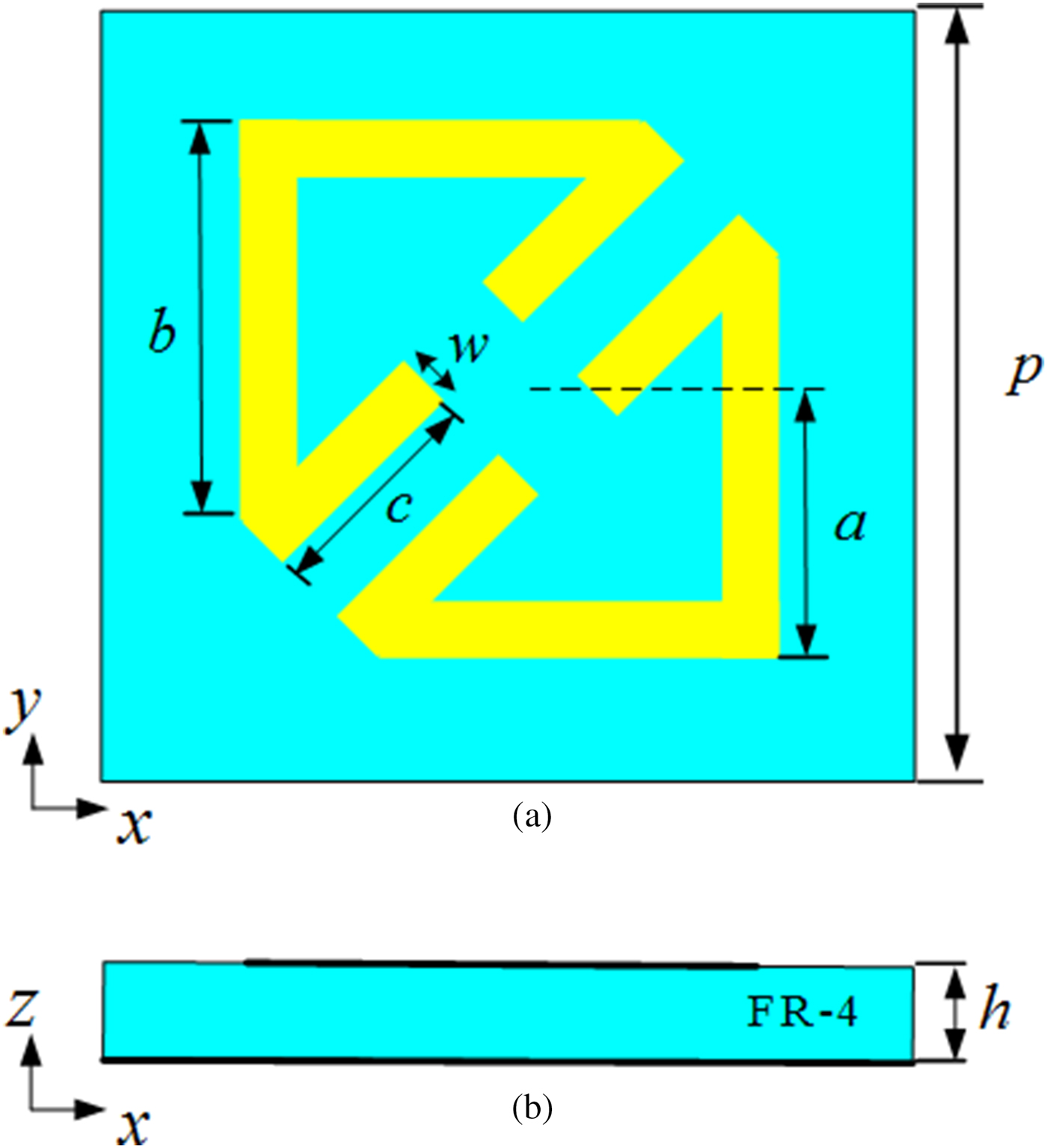
Fig. 1. View of the PCM unit cell. (a) Top view. (b) Side view.
To verify the polarization conversion characteristic of the metasurface, the unit cell is simulated using commercial software ANSYS HFSS 13.0. The periodic boundary conditions in x and y directions and Floquet port in the + z direction are employed in simulation. More specifically, Floquet port is set in the + z direction with wave illuminates along −z direction and the boundary conditions in + x/ − x and + y/ − y directions are set as Master/Slave boundaries, respectively. Take a y-polarized incident wave as an example, we use the definition polarization conversion ratio (PCR) [Reference Jia, Liu, Guo, Li and Gong21] to investigate the efficiency of polarization conversion:
 $$PCR = r_{xy}^2 /\left( {r_{xy}^2 + r_{yy}^2} \right)$$
where  $r_{xy} = \left\vert {\vec E_x^r} \right\vert/\left\vert {\vec E_y^i} \right\vert$ and
  $r_{yy} = \left\vert {\vec E_y^r} \right\vert/\left\vert {\vec E_y^i} \right\vert$ represent the reflection ratio of y-to-x and y-to-y polarization conversion, respectively.
  $\vec E_y^i $ is a linearly y-polarized incident wave,
  $\vec E_x^r $ and
  $\vec E_y^r $ are reflected field along x- and y-axis.
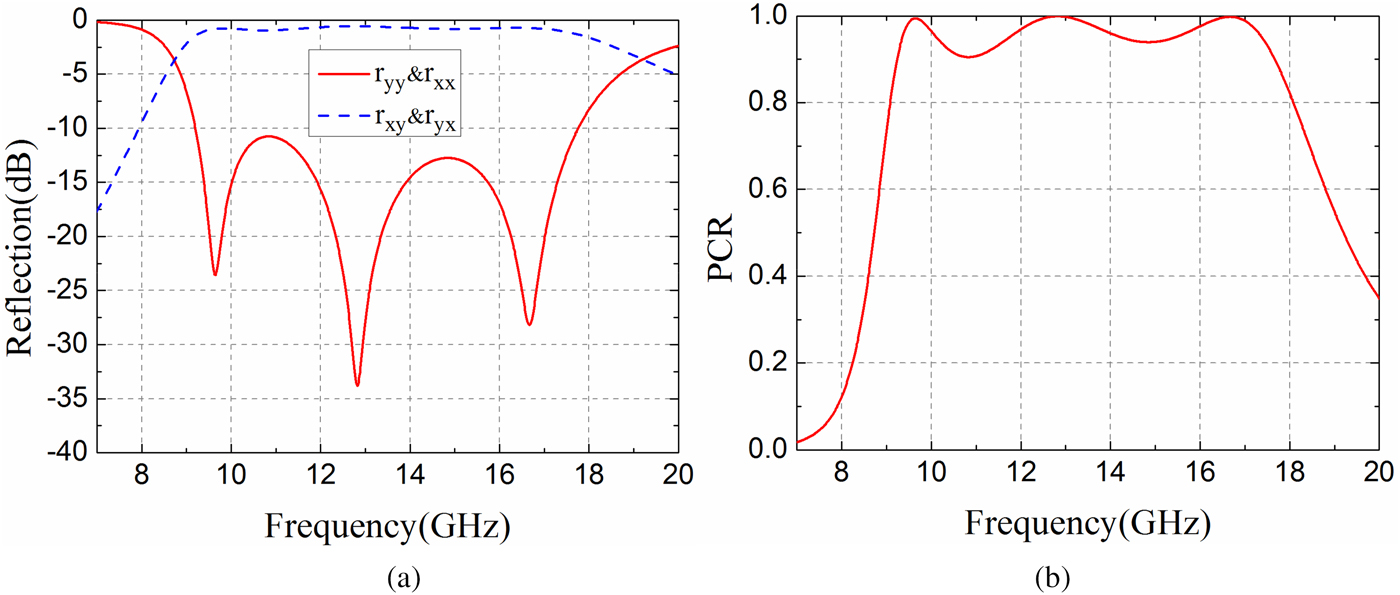
The values of r yy (co-polarization) and r xy (cross-polarization) versus frequency are presented in Fig. 2(a). It is shown that the co-polarization is less than −10 dB in the range of 9.20–17.76 GHz. Figure 2(b) gives the PCR value calculated according (1), which is larger than 0.9 from 9.24 to 17.64 GHz and PCR is nearly 1.0 at three resonant frequencies (9.64, 12.82, and 16.66 GHz). An ignorable difference between 0.9 PCR and −10 dB co-polarization is caused by the dielectric loss of the substrate. Therefore, the y-polarized incident electromagnetic wave is converted to x-polarized reflected wave with conversion efficiency higher than 90% in a wide bandwidth (9.24–17.64 GHz). There are same results for x-polarized incident wave due to the symmetry of the PCM unit.

Fig. 2. Simulated results of the (a) co- and cross-polarization reflections and (b) PCR versus frequency under normal incidence.
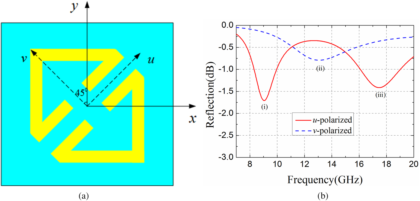
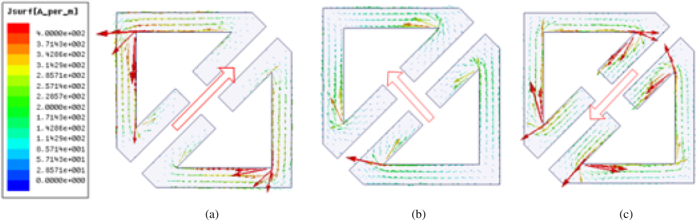
The proposed PCM, an anisotropic structure, is inspired by a cut-wire resonator for polarization conversion and anomalous refraction in [Reference Grady, Heyes, Chowdhury, Zeng, Reiten, Azad, Taylor, Dalvit and Chen12]. Thus we use u- and v-axes to mark the anisotropic axes, as depicted in Fig. 3(a). There are three plasmon resonance eigen-modes excited when electric components along u- and v-axes, as depicted in Fig. 3(b). To study the mechanism of wideband polarization conversion, the current distributions on front layer and bottom layer at three resonance eigen-modes are illuminated in Figs 4 and 5, respectively. It is shown that the currents along x- and y-directions are generated on the top surface, which converts y-polarized incident wave to x-polarized reflected wave. At resonant eigen-mode (i), parallel currents are induced on front layer and bottom layer, as presented in Figs 4(a) and 5(a), which performs like an electric resonance. Thus the eigen-mode is generated by electric resonance. At resonant eigen-modes (ii) and (iii), anti-parallel currents are induced on front layer and bottom layer, which means that the resonances perform like magnetic resonance. The analysis is similar to the explanation introduced in [Reference Chen, Wang, Ma, Qu, Xu, Zhang and Li16]. Take y-polarized incident wave as an example. For electric resonance (i), the induced field can be decomposed into both x-component  $(\vec p_x )$ and y-component
  $(\vec p_y )$, as displayed in Fig. 6(a). The co-polarization is attributed to
  $\vec p_y $. The co-polarization is attributed to
  $\vec p_x $, which generates cross-polarized reflection. For magnetic resonance (ii), the anisotropic characteristic of the PCM generates ‘symmetric’ and ‘antisymmetric’ modes [Reference Grady, Heyes, Chowdhury, Zeng, Reiten, Azad, Taylor, Dalvit and Chen12]. The y-polarized incident wave can be decomposed into two orthogonal equal components along u- and v-axes (
 $\overrightarrow E _u^i $ and
  $\overrightarrow E _v^i $.), respectively. The excited reflected fields are named as
  $\overrightarrow E _u^r $. and
  $\overrightarrow E _v^r $, respectively. The metasurface behaves as a PEC in the symmetric mode which causes out-phase between
  $\overrightarrow E _v^r $ and
  $\overrightarrow E _v^i $. In the antisymmetric mode, the structure behaves as a high impendence surface which generates in-phase between
  $\overrightarrow E _u^r $ and
  $\overrightarrow E _u^i $. Therefore, the total x-polarized reflection is obtained. Similar results can be observed at magnetic resonance (iii). Hence, polarization conversion of the proposed PCM unit is generated by electric and magnetic resonances and the three neighboring resonances ensure wide operating bandwidth.

Fig. 3. (a) u- and v-axes are used to mark the anisotropic axes. (b) Three eigen-modes under normal incidence for u- and v-polarized.

Fig. 4. Surface current distributions on front layer of the proposed PCM unit cell at three eigen-modes (a) (i), (b) (ii), and (c) (iii).

Fig. 5. Surface current distributions on bottom layer of the proposed PCM unit cell at three eigen-modes (a) (i), (b) (ii), and (c) (iii).
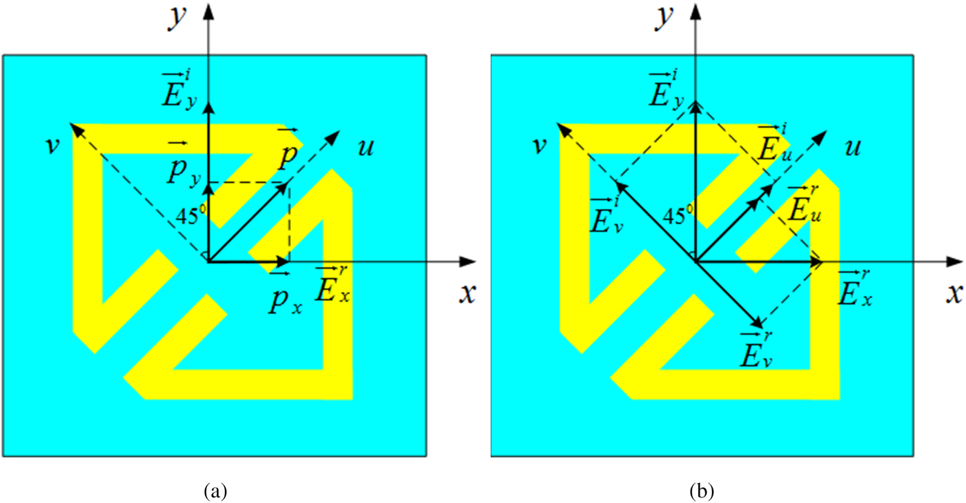
Fig. 6. Schematic of polarization conversion at (a) electric resonance (i) and (b) magnetic resonance (ii).
Moreover, co- and cross-polarization reflection coefficients of the PCM with different key parameters are presented in Fig. 7. The influence of different lengths a on reflection coefficients is depicted in Fig. 7(a). When a varies from 2.1 to 2.3 mm with the other parameters fixed, the first resonant frequency shifts slightly to a lower frequency while the other two resonant frequencies shift to higher ones. Figure 7(b) illuminates the reflection coefficients versus variations of length b for other parameters kept the same. It can be seen that the first resonant frequency performs few changes and the other two resonant frequencies shift to higher frequencies. It is noted that the first resonant frequency and the second one are extraordinary close in the case of b = 3.2 mm, thus only two resonant points displayed within the operation band. As shown in Fig. 7(c), the length of c has a key effect on reflection coefficients. The first resonant frequency remains nearly unchanged and the other two frequencies move to lower frequencies, which is quite different from the influence of b in higher resonant frequencies. For the case of c = 2.3 mm, the first and second frequencies are quite close and combined together. Therefore, these parameters of the PCM are very critical for achieving high PCR over a wideband and the final optimized parameters have been displayed before.

Fig. 7. Simulated co- and cross-polarization reflection coefficients for the case of different (a) parameter a increasing from 2.1 to 2.3 mm, (b) parameter b increasing from 3.2 to 3.6 mm and (c) parameter c increasing from 1.9 to 2.3 mm.
Furthermore, the polarization conversion performances under oblique incident waves need to be investigated. Figure 8 presents the PCR for oblique incidence (θ) under TEz polarization. For θ = 30°, the PCR bandwidth keeps steady and almost the same as normal incidence. For θ = 50°, the proposed PCM unit achieve 0.7 PCR from 9.75 to 17.80 GHz (about a relative bandwidth of 75%). As incidence angle increases, the bandwidth of 0.9 PCR splits into several bands. This is expected because the proposed wideband PCM unit is a multi-plasmon resonator. Figure 9 shows PCR for different polarization angles (φ) under normal incidence. As the symmetry of the structure, the PCR decreases from φ = 0° to φ = 45° and increases from φ = 45° to φ = 90° inversely.
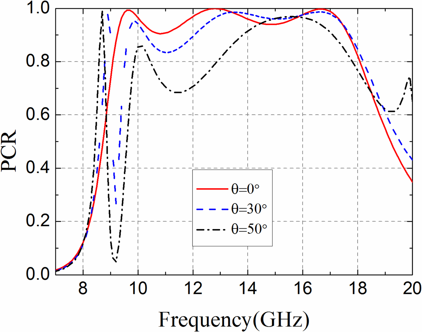
Fig. 8. PCR versus frequency for different incidence angles (θ) under TEz polarization.
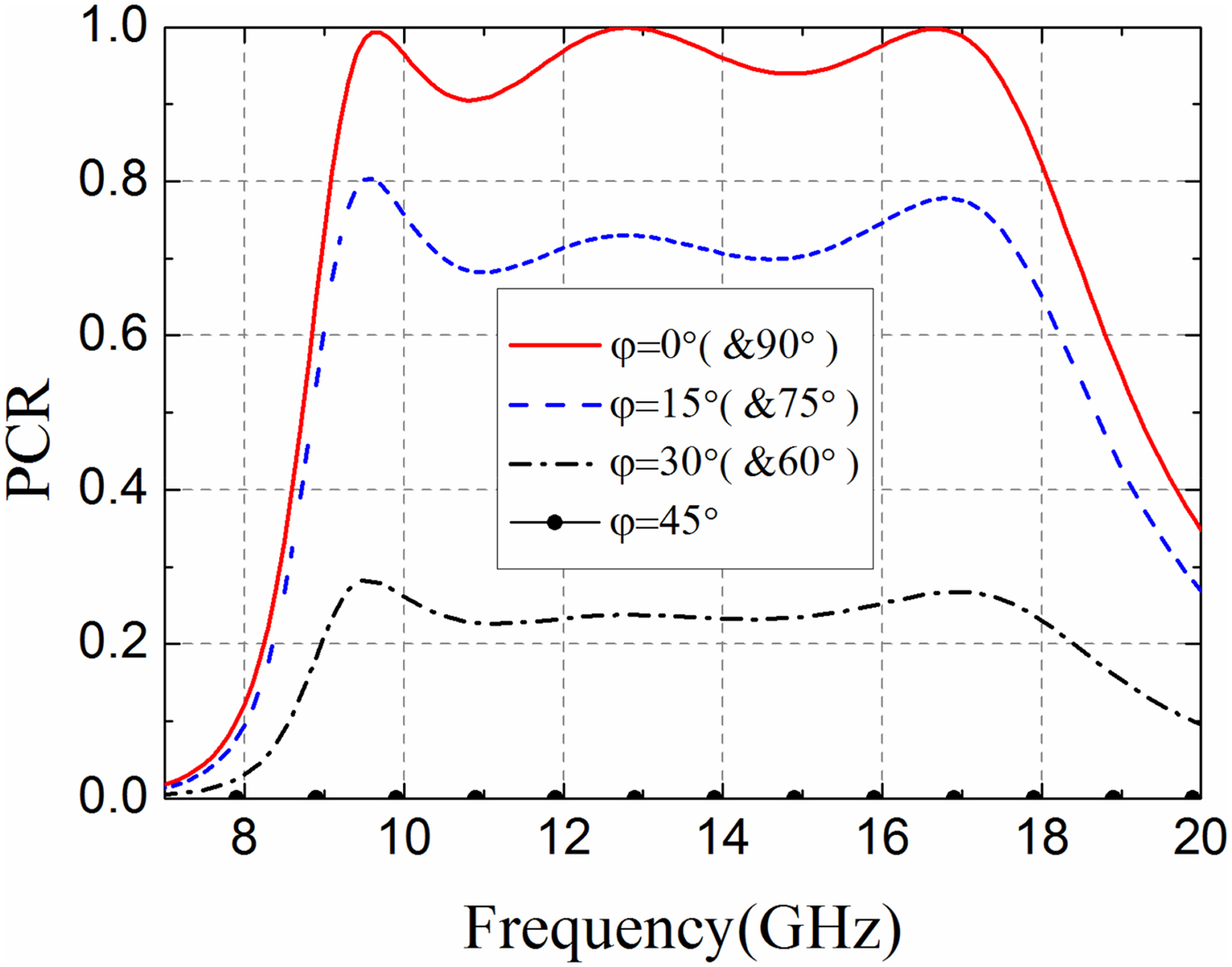
Fig. 9. PCR versus frequency for different polarization angles (φ) under normal incidence.
Study of checkerboard based on PCM
As introduced before, we design a single layer PCM unit, which consists of two oblique symmetry triangle split rings. The schematic square chessboard structure using the proposed PCM unit arranged in units array (set as PCM1) and mirror units array (set as PCM2) is shown in Fig. 10(a). Figure 10(b) shows the co- and the cross-polarization reflections phase difference between the unit and mirror unit, which are 0° and 180°, respectively.
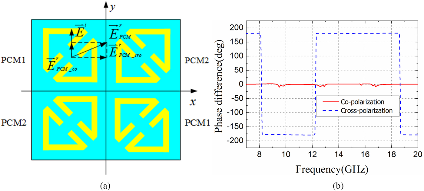
Fig. 10. (a) Schematic of square chessboard structure composed of the PCM units array and mirror units array and (b) Co- and cross-polarization reflections phase difference between the unit and mirror unit.
According to the concept of standard array theory and schematic model described in [Reference Paquay, Iriate, Ederra, Gonzalo and Maagt4], analysis model can be formed as 2 × 2 element array (Fig. 10(a)). Then the reflected field of each element can be expressed as
 $$\overrightarrow E _{PCM1}^r = \left[ {r_{yy} \exp \left( {\,j\mathop \phi \nolimits_{1\_co}} \right)} \right.\left. { + r_{xy} \exp \left( {\,j\mathop \phi \nolimits_{1\_cro}} \right)} \right]A_1 \overrightarrow E _{element},$$
 $$\overrightarrow E _{PCM2}^r = \left[ {r_{yy} \exp \left( {\,j\phi _{2\_co}} \right)} \right.\left. { + r_{xy} \exp \left( {\,j\mathop \phi \nolimits_{2\_cro}} \right)} \right]A_2 \overrightarrow E _{element},$$
where r yy and r xy are co-polarization and cross-polarization reflected coefficient of PCM unit,  $\phi _{1\_{\rm co}} $ and
  $\phi _{2\_{\rm co}} $ are co-polarization reflection phase caused by PCM1 and PCM2,
  $\phi _{1\_{\rm cro}} $ and
  $\phi _{2\_{\rm cro}} $ are cross-polarization reflection phase caused by PCM1 and PCM2, A 1 and A 2 are reflection amplitude of PCM1 and PCM2.
The total reflected field is simply expressed as
 $$\overrightarrow E = \overrightarrow E _{PCM1}^r \cdot AF_1 + \overrightarrow E _{PCM2}^r \cdot AF_2.$$
Array factor AF 1 and AF 2 are described as
 $$AF_1 = \exp \left[ {\,j\left( { - \varphi _x /2 + \varphi _y /2} \right)} \right] + \exp \left[ {\,j\left( {\varphi _x /2 - \varphi _y /2} \right)} \right],$$
 $$AF_2 = \exp \left[ {\,j\left( {\varphi _x /2 + \varphi _y /2} \right)} \right] + \exp \left[ {\,j\left( { - \varphi _x /2 - \varphi _y /2} \right)} \right],$$
where φx = kd sinθ cosφ, φy = kd sinθ sinφ, (θ, φ) is azimuth angle, k = 2π/λ is the wave number, d is the center distance of adjacent element.
For co-polarization phase difference is 0° between PCM1 and PCM2, cross-polarization phase difference is 180° between PCM1 and PCM2
 $$\left \vert {\mathop \phi \nolimits_{1\_co} - \mathop \phi \nolimits_{2\_co}} \right \vert = 0,$$
 $$\left \vert {\mathop \phi \nolimits_{1\_cro} - \mathop \phi \nolimits_{2\_cro}} \right \vert = \pi.$$
Assuming that each element shows equal reflection amplitude (A 1 = A 2 = A) under normal incidence (θ = 0°, φ = 0°), the reflected field (3) is simplified as
 $$\overrightarrow E = r_{yy} A\exp (\,j\phi _{1\_co} )\overrightarrow E _{element}.$$
Therefore, RCS reduction (unit: dB) is calculated by
 $${\rm RCS}\, {\rm reduction} = 10\log \left( {r_{yy}^2} \right).$$
According to (1)
 $${\rm PCR} = 1 - r_{yy}^2.$$
RCS reduction can be expressed with PCR value
 $$RCS\, reduction = 10\log \left( {1 - {\rm PCR}} \right).$$
Therefore, the value of RCS reduction is inversely proportional to the value of PCR. The value of RCS reduction is − ∞ if PCR = 1.0, which is an ideal state of RCS reduction that no energy scattered along incident direction.
Consequently, the structure would exhibit a 10 dB RCS reduction if the PCM unit satisfies
 $$PCR \ge 0.9.$$
Also, the value of co-polarization is less than −10 dB. The derived formula is to predict the RCS reduction value using PCR value of the PCM unit cell approximately.
In this section, we design square and triangle checkerboard PCMs based on the proposed PCM units. The backscattered fields of two PCMs are investigated in theory and analyzed in detail, including normal incidence and oblique incidence. The square checkerboard PCM is consisted of the proposed PCM units array and mirror units array, as shown in Fig. 11(a). Each part consisted of 4 × 4 units array (square size 24 mm × 24 mm,). The whole period size is 2 × 24 mm2 and d x = d y = 24 mm . In this section, the oversize of the checkerboard PCM structure is 96 mm × 96 mm, which consists of four same parts given in Fig. 10(a).
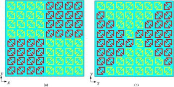
Fig. 11. Schematics of checkerboard PCMs in (a) square and (b) triangle arrangement.
According to standard array theory, the maximum reflected angle (θ, ϕ) ( − 90° ≤ θ ≤ 90°, 0° ≤ ϕ ≤ 360°) satisfies follow equations
 $$\tan \phi = {{\beta _y d_x} / {\beta _x d_y}},$$
 $${\rm sin}^2 \theta = \left( {{{\beta _x} / {kd_x}}} \right)^2 + \left( {{{\beta _y} / {kd_y}}} \right)^2,$$
where d x and d y are the center distance of adjacent element along the x- and y-directions, respectively. β x and β y are the progressive phase shifts between an adjacent element in the x- and y-directions, respectively,which both are 180° phase shift. Therefore, the maximum scattered field direction in ϕ = 45° plane and ϕ = 135° plane.
Schematic of the triangle checkerboard PCM contains 8 × 8 units is shown in Fig. 11(b). Similarly, the maximum scattered field direction of triangle checkerboard PCM structure in ϕ = 0° plane and ϕ = 90° plane. The maximum reflected angle (θ, ϕ) (− 90° ≤ θ ≤ 90°, 0° ≤ ϕ ≤ 360°) of triangle checkerboard PCM structure satisfies
 $${\rm sin}^2 \theta = \left( {{{\beta _x} / {k\sqrt 2 d_x}}} \right)^2 + \left( {{{\beta _y} / {k\sqrt 2 d_y}}} \right)^2.$$
Normal incidence
Two 16 × 16 units arrays with the area of 96 mm × 96 mm based on the proposed PCM unit are designed and measured, respectively, as shown in Fig. 12(a) and (b). Both samples were measured in the anechoic chamber of the Northwestern Polytechnical University. Two identical standard horn antennas operating from 1 to18 GHz are used as transmit and receive antennas which are connected to a network analyzer. RCS reduction is normalized with an equal size metallic ground plate to reduce the influence of noise in the anechoic chamber. As presented in Fig. 12(c), the two horn antennas are placed horizontally along the same direction for TEz polarization measurement. Inversely, the two horn antennas are placed perpendicularly for TMz polarization measurement, as given in Fig. 12(d).

Fig. 12. Sample of (a) square and (b) triangle checkerboard PCM.(c) Measurement setup for TEz polarization and (d) TMz polarization.
Simulated and measured RCS reduction versus frequency under normal incidence for both checkerboard PCMs are depicted in Fig. 13. Both structures exhibit over 60% relative bandwidth of 10 dB RCS reduction with respect to the equal-sized metallic plate, which is expectable for they are designed based on the same PCM unit cells. An acceptable discrepancy is attributed to fabrication tolerance and measurement deviation. What is more, the curve of RCS reduction versus frequency has the same tendency with the PCR versus frequency. There are some deviations and frequency shifts between simulations and analysis according to 0.9 PCR bandwidth of the PCM unit (9.24–17.64 GHz and a relative bandwidth of 62.5%). The main reason is due to that (7) and (9) are derived based on standard array theory without considering edge diffractions.

Fig. 13. Simulated and measured RCS reduction versus frequency under normal incidence for both checkerboard PCMs.
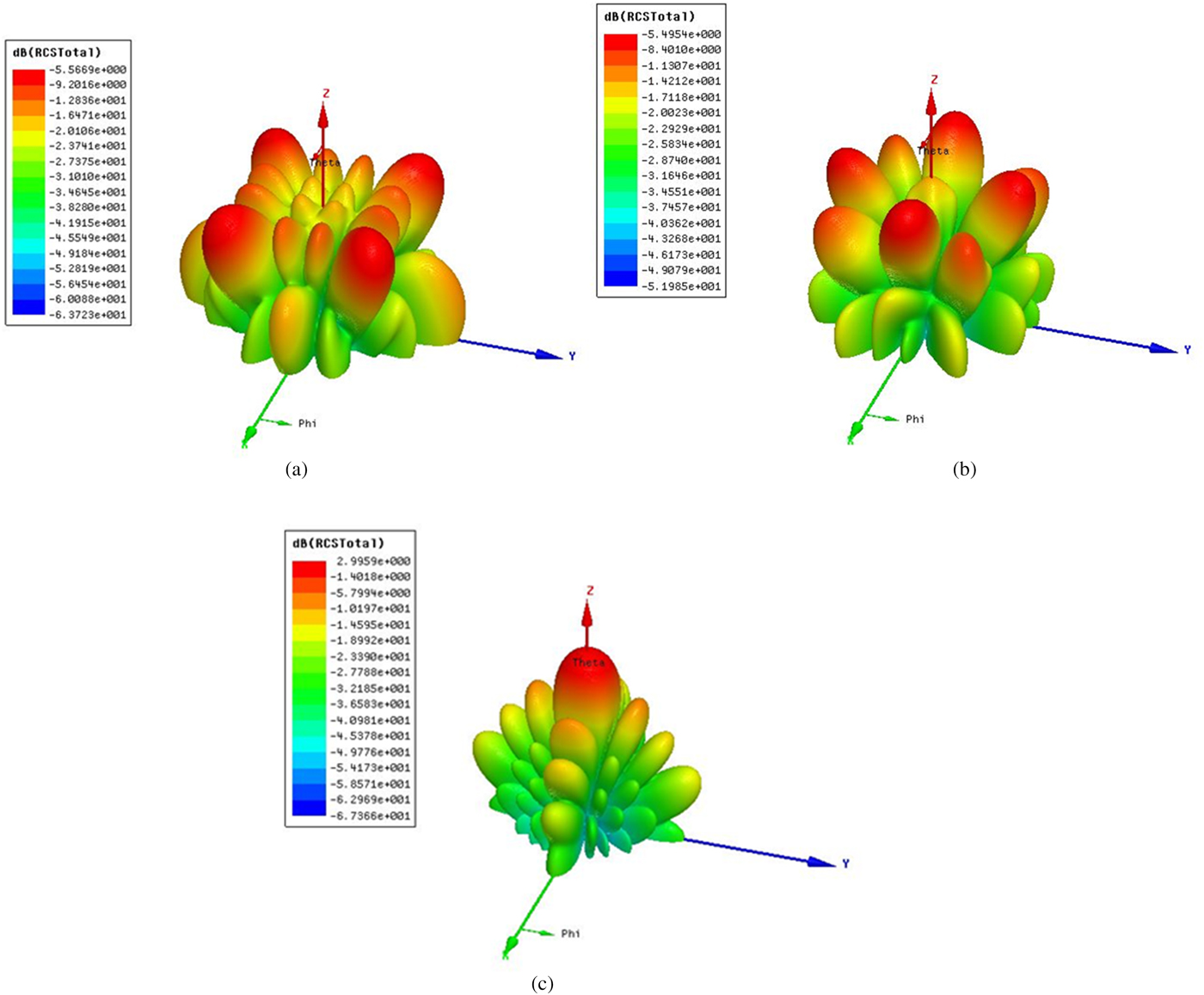
Figure 14 presents the 3-D bistatic scattered fields at 13.0 GHz for two checkerboard PCMs and equal size metallic plate (PEC). Both checkerboard PCMs redirect the incident wave to other inessential directions. Also, the triangle and square show different redirected fields due to different arrangements of PCM unit cells.

Fig. 14. 3-D bistatic scattered fields at 13.0 GHz under normal incidence for (a)square, (b) triangle, and (c) equal-sized metallic plate.
Moreover, according to (11a) and (11b), the scattered beams appear at ϕ = 45° plane and ϕ = 135° plane, the maximum scattered beam direction is θ = 42.84°. The bistatic scattered fields along ϕ = 45° (ϕ = 135°) plane for square checkerboard PCM is shown in Fig. 15(a). It is illustrated that the maximum RCS is θ = 40°, which is close to the angle predicted by (10b). According to (12), the scattered beams appear at ϕ = 0° plane and ϕ = 90° plane, the maximum scattered beam direction is θ = 28.73°. The bistatic scattered fields along ϕ = 0° (ϕ = 90°) plane for triangle checkerboard PCM is given in Fig. 15(b). It is illustrated that the maximum RCS is θ = 28°, which is close to the angle predicted by (12). The difference may be due to that (11b) and (12) are derived based on standard array theory without considering coupling between elements and diffraction from the edges.
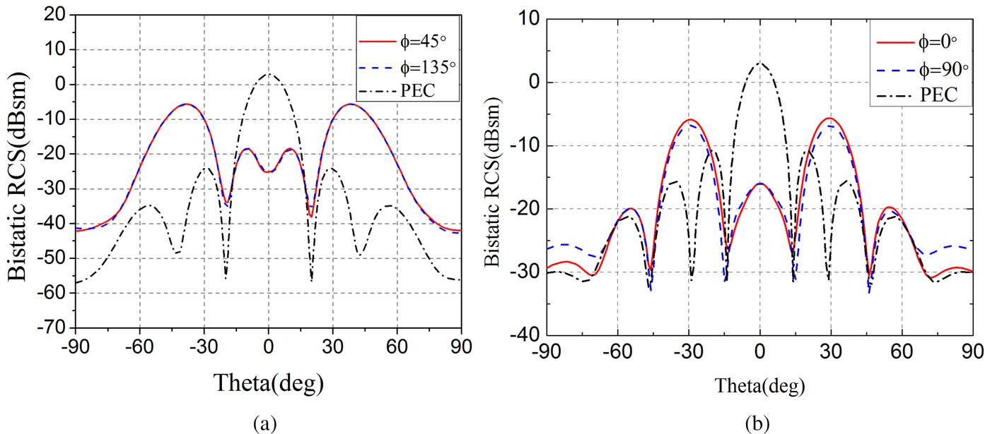
Fig. 15. Bistatic RCS for (a) square checkerboard PCM along ϕ = 45° plane and (b) triangle checkerboard PCM along ϕ = 0° plane compared with equal size metallic plate (PEC).
Oblique incidence
As introduced in the section Design and analysis of PCM unit, the PCR value of the PCM unit depends on incidence angle and polarization of incidence wave. Similar to the analysis of checkerboard EBG surface under oblique incidence [Reference Chen, Balanis and Birtcher9], the RCS reduction at a range of oblique angles for both TEz and TMz polarizations are investigated in this section.
In [Reference Jiang, Xue and Gong22], it is validated in detail that square checkerboard structure based on PCM unit cells could achieve RCS reduction within certain angles. The monostatic RCS for square checkerboard under oblique incidence is not shown for simplicity. The monostatic scattered fields at 13.0 GHz for TEz and TMz polarization along ϕ = 0° (ϕ = 90°) plane for triangle checkerboard PCM and equal size metallic plate (PEC) are given in Fig. 16(a) and (b), respectively. The measured results and simulated ones are in good agreement except for some angles. The main reason may be due to the influence of noise and measurement deviations. For example, the incident wave was not strictly plane wave and the sample was not placed strictly perpendicular to transmitting and receiving antennas. Though, it is illustrated that the checkerboard PCM structure reduces RCS significantly within certain incident angles.

Fig. 16. Monostatic RCS at 13.0 GHz for (a) TEz polarization and (b) TMz polarization along ϕ = 0° (ϕ = 90°) plane for triangle checkerboard PCM, and equal size metallic plate (PEC).
Conclusion
In this work, a wideband PCM unit cell composed of two oblique asymmetry triangle split rings is presented for RCS reduction. The simulated results show the PCM unit has more than 90% polarization conversion efficiency from 9.24 to 17.64 GHz and two checkerboard structures using the PCM units achieve over 60% relative bandwidth of 10 dB RCS reduction (9.24–17.64 GHz) under normal incidence with respect to the equal-sized metallic plate. The relationship between RCS reduction value and PCR value is derived, which serves as a guideline for predicting the RCS reduction bandwidth of the chessboard PCM. The triangle checkerboard PCM shows different backscattered fields with respect to the square one due to a different arrangement of PCM unit cells. For oblique incidence, the triangle one also reduces RCS obviously in certain angular due to the angle dependence of PCM unit cell. Fabricated sample and measured results of both checkerboard PCMs are presented. The simulated results agree well with simulated ones. It is observed that the proposed structure has a potential application for stealth technologies due to its broadband and simple design. Meanwhile, the triangle checkerboard PCM provides an alternative solution to reduce RCS.
Acknowledgement
We thank the reviewers and editor for their valuable comments and warm work earnestly.
 Qi Zheng was born in Anhui Province, China, in 1993. He received the B.Sc. in Mathematics and Applied Mathematics from the School of Science, Northwestern Polytechnical University (NPU), 2014. Then, he received the M.Sc. in Electromagnetic Field and Microwave Technology from the School of Electronic and Information, NPU, 2016. Now, he is pursuing the Ph.D. degree in Electronic Science and Technology from the School of Electronic and Information, NPU. His research interests include the design of reflectarray, metamaterials-based antennas, polarization manipulation devices, RCS reduction. E-mail: zhq930908@163.com
 Chenjiang Guo was born in Shannxi Province, China, in 1963. CIE Senior Member, Antenna Society Committee Member. He received the M.Sc., B.Sc, and Ph.D. in School of Electronics and Information, Northwestern Polytechnical University in Xi'an city, China, in 1984, 1987, and 2007, respectively. He is a professor in School of Electronics and Information NWPU. He has published more than 140 research papers. His research interests include EMI/EMC, the antenna theory and design, and the microwave circuit design. E-mail:cjguo@nwpu.edu.cn
 Haixiong Li, was born in Shannxi Province, China, in 1982 and is a IEEE Student Member, CIE Student Member. He received the B.Sc. degree in School of Electrical Information Science & Engineering, Lanzhou University in Lanzhou city, China in 2006. He received the M.Sc. degree in School of Information Science and Technology, Xiamen University in Xiamen city, China in 2013. He is presently working on his doctoral degree in School of Electronics and Information, Northwestern Polytechnical University in Xi'an city, China. His research interests include electromagnetic metamaterials and MIMO antenna design. E-mail: lihaixiong_02@163.com
 Jun Ding was born in Shannxi Province, China, in 1964. She received the MSc., BSc., and Ph.D. in School of Electronics and Information, Northwestern Polytechnical University in Xi'an city, China, in 1986, 1989 and 2005 respectively. She is a professor in School of Electronics and Information NWPU. She has published more than 100 research papers. Her research interests include: electromagnetic metamaterials, the antenna theory and design, and the microwave circuit design. E-mail: dingjun@nwpu.edu.cn