


NOMENCLATURE
- Hc
-
travel of the ball screw
- Lc
-
length of the lead
- nc
-
rounds of the bidirectional thread
- vs
-
velocity of the slider
- ωm
-
speed of the DC motor
- x
-
coordinate of the joint on the x axis
- y
-
coordinate of the joint on the y axis
- i
-
number of Joint A
- Hp
-
distance from the bottom of the motor to the base of the threaded shaft
- ls,r
-
length of the rod
- θs,min
-
minimum value of the crossed rods
- θs,max
-
maximum value of the crossed rods
- lu,r
-
length of the rib
- lu,s
-
length of the stretcher
- lu,t
-
distance from the runner to the top of the umbrella
- lu,l
-
distance from the connective position of stretcher and rib to the top of the umbrella
- θu
-
angle between the rib and tube
- f
-
oscillating frequency of the modular wings
- Ui
-
instantaneous voltage
- Ii
-
instantaneous current
- Pi
-
input power
- Fp
-
thrust of the propelling machinery
- Fp,t
-
forces measured by the transducers after motor rotation
- F p,0
-
forces measured by the transducers before motor rotation
- Fi
-
inertial force of the propelling machinery
- Fa
-
aerodynamic force of the umbrella-like wing
- mi
-
mass of each part of the propelling machinery
- ai
-
corresponding acceleration
- Hu
-
travel of the wing
- k
-
number of the SLE elements
- Vs
-
velocity of the single wing
- Fa,m
-
average aerodynamic force of the wing
- Ve,u
-
velocity of the upper wing
- Ve,d
-
velocity of the lower wing
- Pi,m
-
arithmetic average of the power
- Fp,m
-
arithmetic average of the thrust of the propelling machinery
1.0 INTRODUCTION
Many animals have excellent flight and swimming capabilities that have developed over a long period of natural evolution. People have acquired basic cognition on the theory of propulsion of these animals and have published many studies in the past few centuries. With the development of high-speed photography and particle image velocimetry, researchers have provided insight through detailed observations of the morphology, kinematics and dynamics of birds and fish(Reference Shyy, Aono, Chimakurthi, Trizila, Kang, Cesnik and Liu1-Reference Shadwick and Lauder5). The understanding of the physical principles of bird flight and fish swimming have in turn motivated efforts to replicate this performance. Many research teams have developed a series of bionic robots that mimic the efficient propulsion of animals.
Flapping-wing air vehicles and fishlike robots are representative of the research on bionic robots. Typical bionic flying robots have been proposed in Refs Reference Fearing, Chiang, Dickinson, Pick, Sitti and Yan6-Reference Delautier11: they can combine lifting capacity, hovering and propulsion by imitating the flight of insects or birds. Flexible wings(Reference Mazaheri and Ebrahimi12) and passively morphing ornithopter wings(Reference Billingsley, Slipher, Grauer and Hubbard13,Reference Mueller, Gerdes and Gupta14) have been developed to increase the net lift over the flapping cycle, and both have a favourable effect. However, the mechanism of how geometrically nonlinear effects and the anisotropy of the structure impact the aerodynamic characteristics of the flapping wing remains unknown(Reference Lucas, Johnson, Beaulieu, Cathcart, Tirrell, Colin, Gemmell, Dabiri and Costello15), and the efficiency of flapping bionics is very low compared to flying organisms. The propulsion mechanisms are mainly concentrated at the small and micro size due to the limitations of their weights and flapping frequencies.
Fishlike robots have been designed by modelling the swimming methods of fish: the robots wave tail fins and pectoral fins to navigate and turn in water(Reference Zhang, Guo and Asaka16,Reference Licht, Polidoro, Flores, Hover and Triantafyllou17) . Fishlike robots can easily obtain a lift force against gravity because of the greater density of water compared with air. Hence, the weight of fishlike robots is insignificant. The tail fins and pectoral fins of fishlike robots can be oscillated at a low frequency(Reference Epps, Valdivia y Alvarado, Youcef-Toumi and Techet18). With this behaviour, fishlike robots can generate high-efficiency thrust and small turning angles with low energy consumption(Reference Hover, HAugustsdal and Triantafyllou19).
In addition to bionic flying robots and fishlike robots, many other bionic propulsion mechanisms have been successfully designed and developed. For example, Jones and Platzer designed a flapping-wing-propelled micro air vehicle. The mounting location of the flapping wings was different from a traditional ornithopter, i.e. they were arranged in a biplane configuration and flapped in counterphase(Reference Jones and Platzer20). Special composite materials have been developed to allow robot jellyfish to mimic the bell deformation cycle of jellyfish based on their high locomotive efficiency and relatively simple design(Reference Villanueva, Smith and Priya21-Reference Nawroth, Lee, Feinberg, Ripplinger, McCain, Grosberg, Dabiri and Parker23).
Thus, many bionic propulsion mechanisms have been successfully designed and developed. Some of them have shown high efficiency and performance under testing. The excellent construction, function, and performance of living systems are attractive research targets for translating the evolutionary successes of natural species into artificial systems. To this end, our work has focused on designing a new type of propulsion mechanism inspired by flying birds and swimming jellyfish. This type of propulsion uses modular umbrella-like wings to produce thrust by oscillating symmetrically in counterphase.
In this paper, we discuss the design of a new propulsion mechanism and the results of performance tests. We first introduce the kinematics of umbrella-like wings and the underlying theory in Section 2. A CAD model of the propelling machinery with modular umbrella-like wings is presented in Section 3, and the structural parameters and assembly relationships of the mechanism are described in detail. In Section 4, a prototype is fabricated to test the kinematic and mechanical properties, and a planar diagram of the experiment is presented. Finally, tests with different parameters are discussed in Section 5.
2.0 PRINCIPLE AND MOTION OF THE NEW TYPE OF PROPULSION
Avians can support their bodies in the air and achieve forward flight by repeatedly beating their wings. Wing-beat kinematics is highly complex and has been described in detail elsewhere(Reference Hedrick, Tobalske and Biewener24-Reference Muijres, Bowlin, Johansson and Hedenström28). There are several key features of wings flapping in a motion period that inspired us to develop a new type of propulsion.
First, the wing is extended and almost flat during the downstroke, while the surface of the wing is inclined with respect to the flight direction and partly folded during the upstroke. Next, the primary feathers rotate around their longitudinal axis to create gaps to let air pass freely during the upstroke but form a tight, coherent surface during the downstroke(Reference Hedrick, Tobalske and Biewener24).
The projections on the horizontal plane of the total surface area change through the control of folding and unfolding wings and through the expansion and occlusion of the primary feathers. The result is a reduced magnitude of negative lift produced in the upstroke phase(Reference Crandell and Tobalske27). Birds can take advantage of this asymmetrical deformation to generate continuous force. Inspired by this ability, we conceive a neoteric propulsion technique in which a pair of flapping wings oscillates symmetrically in counterphase to generate propulsive force. Considering how the jellyfish generates a stable thrust for its axisymmetric shape(Reference McHenry and Jed29), the flapping wing is improved to an umbrella-like wing.
The typical movement in a cycle consists of two phases (Fig. 1). Figure 1(a–c) show the forward motion of the two umbrella-like wings. The upper wing is closed and is moving downwards at the beginning of this phase. The lower wing is patulous and is moving upwards. The status of the two umbrella-like wings is shown in Fig. 1(a). Each of the upper and lower umbrella wings acquires a momentum under the action of the air: the upper umbrella wing has passively opened to its fullest, and the lower umbrella wing has passively closed to some degree after a time, as shown in Fig. 1(b). Then, the upper and lower wings are moving toward each other. The distance between the upper and lower wings is smallest at the final moment of this phase, as shown in Fig. 1(c).
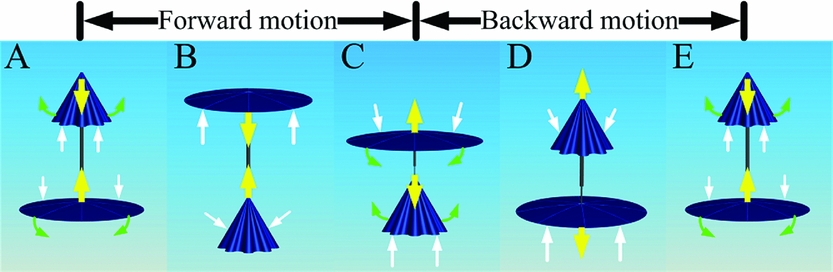
Figure 1. Sectional schematic of umbrella-like wings approaching each other in the phase of forward motion (a–c) and backward motion (c–e). Yellow arrows denote the vertical movement direction of the wings. Green arrows denote the wings’ direction of rotation. White arrows denote the net forces acting on the wings.
Figure 1(c–e) show a backward motion of the two umbrella-like wings. Each movement direction of the two wings is opposite compared with the forward motion, as shown in Fig. 1(c). The upper wing has passively closed, and the lower wing has passively opened to its fullest for a short time, as shown in Fig. 1(d). The distance between the two umbrella wings is longest at the final moment of this phase, as shown in Fig. 1(e).
The upper wing opens to its fullest status, and the lower wing closes to some degree in the course from status B to status C. The projection area of the upper wing is significantly larger than for the lower wing; thus, the upper wing would predominantly produce thrust compared with the lower wing, which would produce a small drag. Similarly, the upper wing would produce a small drag and the lower wing would produce a large lift in the course from status D to status E. Thus, a persistent thrust is obtained by the modular umbrella wings throughout the whole period.
Modular umbrella-like wings used for propulsion have two remarkable characteristics. The first is that the change in the projection area of the umbrella-like wing (wing stretch and closure) is similar to the deformation of a bird's wing(Reference Hedrick, Tobalske and Biewener24). The second is that the shape of the umbrella-like wing is analogous to the bell of a jellyfish and would generate a stable thrust for an axisymmetric shape(Reference Dabiri, Colin and Costello30).
3.0 DESIGN OF THE PROPULSION MECHANISM
To achieve the function of this propulsion system, the mechanical design of the propelling machinery is projected as shown in Fig. 2. The propelling machinery consists of three parts: the driving mechanism, the stroke amplifier and a pair of umbrella-like wings. The driving mechanism can transmit the rotational motion of the motor to a reciprocating motion. The stroke amplifier can amplify the displacement of the reciprocating motion. The upper and lower wings are then installed on each end of the amplifier to make the umbrella-like wings oscillate symmetrically in counterphase with a large travel.
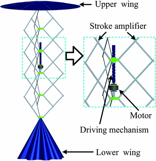
Figure 2. CAD model of the propelling machinery.
3.1 Driving mechanism
Traditional flapping wings use a slider crank mechanism or cam to transmit the rotational motion of the motor to a flapping motion(Reference Gerdes31). The crank mechanism can generate inertial force with the acceleration of the centroid of the slider and pushrod. It is difficult to offset the inertial force for a common method. In this article, a ball screw mechanism with a bidirectional thread was designed to achieve this function, thereby directly transmitting the high-speed rotational motion to a low-frequency reciprocating motion.
A ball screw is a mechanical linear actuator that translates rotational motion to linear motion with little friction. The ball screw usually achieves reversal of the linear motion by changing the direction of rotation; however, frequent changes in the direction of rotation when rotating at high speed can damage the DC motor. Thus, a bidirectional thread ball screw has been developed to avoid changing the movement direction of the motor. The parameters of the screw and assembly relationships of these parts are shown in Fig. 3.
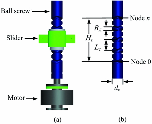
Figure 3. Parameters and assembly relationships of the screw.
Two threaded shafts rotate clockwise and anti-clockwise to provide a closed helical raceway. A slider moves along the raceway normally, as in a traditional ball screw. However, the position of the balls in the slider is changed to lead the balls from one threaded shaft to another when the slider reaches each end of the screw, thus achieving the reciprocating motion of the driving mechanism. The relationship between these parameters is as follows:
 $$\begin{equation}
{H_c} = {L_c} \cdot {n_c},
\end{equation}$$
$$\begin{equation}
{H_c} = {L_c} \cdot {n_c},
\end{equation}$$
where Hc is the travel of the bidirectional thread of the ball screw, Lc is the length of the lead, and nc is the number of rounds of the bidirectional thread.
The relationship between the movement speed of the motor and slider is obtained as follows:
 $$\begin{equation}
{v_s} = {L_c}{\omega _m}/2\pi ,
\end{equation}$$
$$\begin{equation}
{v_s} = {L_c}{\omega _m}/2\pi ,
\end{equation}$$
where vs is the velocity of the slider, and ωm is the speed of the DC motor.
3.2 The stroke amplifier
The bidirectional thread of the ball screw can translate rotational motion to linear motion for a short distance, although the travel of the driving mechanism should be enlarged though a stroke amplifier. In this paper, a deployable structure is used as a stroke amplifier to enlarge the travel. Deployable structures consist of units consisting of pairs of bars connected at a joint that allow a compact and deployed configuration(Reference Zhao, Chu and Feng32). The most widely adopted deployable structures are based on Scissor-Like Elements (SLEs)(Reference Langbecker and Albermani33).
Typically, an SLE has a pair of equal-length bars connected to each other at an intermediate point by a revolute joint. The joint allows the bars to rotate freely around an axis that is perpendicular to their common plane. Several SLEs are linked in appropriate arrangements to construct deployable structures(Reference Nagaraj, Pandiyan and Ghosal34). A CAD model of the ternary flat deployable structures is shown in Fig. 4.
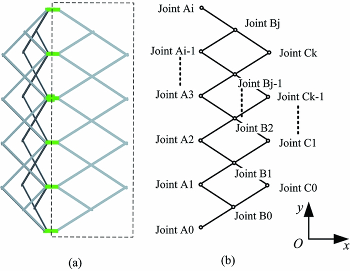
Figure 4. Ternary flat deployable structures: (a) Isotropic view of the structures; (b) One-third of the structures in a flattened view of the polygons with their sides.
The assembly is a mechanism with one degree of freedom from the stowed/folded configuration to the end of deployment. The bars are considered rigid rods, and the relationships of each joint can then be obtained from the basic geometric constraints for ternary flat deployable structures, as given by
 $$\begin{equation}
\left| {{x_A}_i - {x_A}_{i - 1}} \right| = \left| {{x_A}_{i - 1} - {x_A}_{i - 2}} \right|,\\
\end{equation}$$
$$\begin{equation}
\left| {{x_A}_i - {x_A}_{i - 1}} \right| = \left| {{x_A}_{i - 1} - {x_A}_{i - 2}} \right|,\\
\end{equation}$$
 $$\begin{equation}
\left| {{y_A}_i - {y_A}_{i - 1}} \right| = \left| {{y_A}_{i - 1} - {y_A}_{i - 2}} \right|,
\end{equation}$$
$$\begin{equation}
\left| {{y_A}_i - {y_A}_{i - 1}} \right| = \left| {{y_A}_{i - 1} - {y_A}_{i - 2}} \right|,
\end{equation}$$
The two joints of an SLE in the middle are connected to the joints of the slider and the kickstand of the motor. The joint connected to the slider functions as an active part, while the joint connected to the kickstand of the motor is an immovable part. Each assembly number of SLEs below and above the immovable joint is the same to remove the inertial force generated by the rods of the SLEs. The deployment and driving mechanism are assembled as shown in Fig. 5, with the deployable structure in the fully contracted configuration shown on the left and the deployable structure in the fully deployed configuration shown on the right.
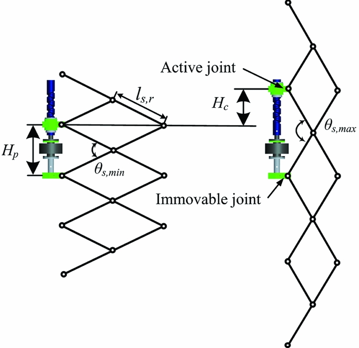
Figure 5. Assembly diagram of the deployment and driving mechanism.
The length of the rod in relation to the distance between the slider and motor can be expressed as follows:
 $$\begin{equation}
{H_p} = 2{l_{s,r}}\sin ({\theta _{s,\min }}/2),
\end{equation}$$
$$\begin{equation}
{H_p} = 2{l_{s,r}}\sin ({\theta _{s,\min }}/2),
\end{equation}$$
 $$\begin{equation}
{H_p} + {H_c} = 2{l_{s,r}}\sin ({\theta _{s,\max }}/2),
\end{equation}$$
$$\begin{equation}
{H_p} + {H_c} = 2{l_{s,r}}\sin ({\theta _{s,\max }}/2),
\end{equation}$$
where Hp is the distance between the bottom of motor and the base of threaded shaft, ls,r is the length of the rod, and θs,min and θs,max are the minimum and maximum values of the crossed rods.
3.3 Structure of the umbrella-like wing
The modular umbrella-like wings consist of two identical cone-shaped bells are installed at each end of the stroke amplifier. This pair of wings is actuated by deployment to symmetrically oscillate in counterphase with a large travel. The wing can achieve momentum under the action of the air and open to its fullest when moving downwards, and it can close to some degree due to the same mechanism when moving upward. The status of the umbrella-like wings during their motion is shown in Fig. 6.
Figure 6. Sketch of the umbrella-like wing: (a) the closed state; (b) the outspread state.
All of the ribs rotate around the pin as a function of the aerodynamic force, inertial force and gravity; thus, the wings passively open or close when the direction of motion changes. As each runner is connected to the rib by the stretcher, the runners constitute a structure with a rod-crank mechanism, wherein the runner can slide up or down along the tube when the status of the wing changes. To reduce the impact generated by the runner, two compressed springs are fixed to the ends of the runner.
In the planar diagram of the umbrella and its basic parameters shown in Fig. 7, the length of the rib is denoted by lu,r , the length of the stretcher is lu,s , the distance from the runner to the top of the umbrella is lu,t , the distance of the connective position between stretcher and rib to the top of the umbrella is lu,l , and the angle between the rib and tube is indicated by θu .
Figure 7. Schematic geometry of the umbrella wing.
According to the triangular relationship between the corners and each side, the equation is as follows:
 $$\begin{equation}
{\theta _u} = \arccos [(l_{u,l}^2 + l_{u,t}^2 - l_{u,s}^2)/2{l_{u,l}}{l_{u,t}}]
\end{equation}$$
$$\begin{equation}
{\theta _u} = \arccos [(l_{u,l}^2 + l_{u,t}^2 - l_{u,s}^2)/2{l_{u,l}}{l_{u,t}}]
\end{equation}$$
3.4 Selection of parameters
Based on the above research, the parameters of the propelling machinery could be confirmed based on the assembly relationships among all parts of the machinery for certain values of travel and reciprocating frequency.
The reciprocating frequency of the modular umbrella-like wings can be obtained by solving Equations (1) and (2):
 $$\begin{equation}
f = {\omega _m}/4\pi {n_c}
\end{equation}$$
$$\begin{equation}
f = {\omega _m}/4\pi {n_c}
\end{equation}$$
where f is the movement frequency of the modular umbrella wings.
We completed many tests of the transmission mechanism in previous studies. The reciprocating frequency of the modular umbrella-like wings is controlled in the range of 1 to 3 Hz based on our experience, and the travel of the slider is controlled to approximately 0.20 m. The parameters of the ball screw mechanism with a bidirectional thread designed according to Equation (1) are given in Table 1.
Table 1 Parameters of the ball screw
The reciprocating travel of the slider is calculated by Equation (1), where Hc equals 0.18 m. The minimum angle between the two crossed rods θs,min equals 60°, while the maximum angle between the two crossed rods θs,max equals 120°. The length of the rod is calculated by Equations (5) and (6), where ls,r equals 0.225 m, and Hp also equals 0.225 m.
It took a relatively long time for a closed wing to open to its fullest in earlier tests. Hence, the angle between the rib and tube ranges from 40° to 70°. The parameters of the umbrella-like wing are shown in Table 2. The value of lu,t ranges from 70 mm to 170 mm as calculated by Equation (7) for a certain angle range.
Table 2 Parameters of the umbrella-like wing
4.0 EXPERIMENTAL SET-UP AND DATA PROCESSING METHOD
A test apparatus, as shown in Fig. 8, was built to investigate the kinematic and mechanical characteristics of the modular umbrella-like wings. This test measures the instantaneous thrust and inertial forces, the velocity of the upper and lower wings and the driving power usage in hovering flight. Different input powers were tested to compare their dynamic performance.
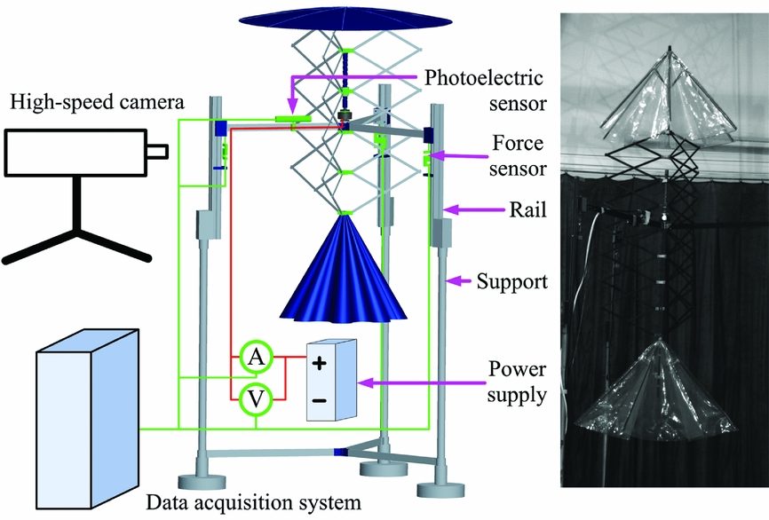
Figure 8. Experimental set-up.
A prototype of the propelling machinery was constructed according to the model, as shown in Fig. 2. The basic design of this prototype is presented in Section 3. The test bed consists of a main support, rails, a prototype, a lithium-polymer battery, a receiver, a speed controller, and data acquisition equipment. The sensors used in this paper include a speed sensor, force sensor, current sensor and voltage sensor. A high-speed camera was used to visualise the movement of the reciprocating wings.
All signals were acquired using National Instrument equipment and a PC running custom-designed software written in LabView. A custom LabView routine was used to control the entire process. The sample frequency was 10 KHz. This frequency was confirmed based on the response time and sensitivity of the sensors. The data acquisition process began by recording the forces, motor speed, input current and voltage using the calibration factors. The data were then filtered using a low-pass digital filter with a cut-off frequency of 200 Hz. This cut-off frequency can filter out the high-frequency noises generated by motor jitter or the wing aerodynamics.
The main kinematic parameters of this propelling machinery include the velocities of the modular umbrella-like wings and the rotational speed of the motor. To calculate the inertial force of the machinery working in hovering flight, the accelerations of the deployed structures should also be measured. The rotational speed of the motor was measured by a photoelectric sensor in a non-contact way. The movement of the object being tested can be affected by the displacement sensor when using a traditional approach. Hence, we first took photos of the propelling machinery using a high-speed camera in the tests. Then, an object tracking method(Reference Comaniciu, Ramesh and Meer35,Reference Yilmaz, Javed and Shah36) was applied to these images to acquire the displacement of the object.
It is important to understand how the aerodynamic forces generated by the umbrella-like wings change as a function of time. The propelling forces generated by the umbrella wings in a reciprocating motion at different input powers were measured to analyse the propelling performance of the machinery. The input power can be calculated as
 $$\begin{equation}
{P_i} = {U_i} \cdot {I_i},
\end{equation}$$
$$\begin{equation}
{P_i} = {U_i} \cdot {I_i},
\end{equation}$$
where Ui is the instantaneous voltage measured by the voltage transducer and Ii is the instantaneous current measured by the current sensor.
The propulsive forces generated by the umbrella wings in hovering flight were measured in the tests. As the umbrella-like wings are reciprocating vertically, the direction of the propulsive force is consistent with the direction of movement. To relieve the constraint on the propelling machinery in the vertical direction, sliding rails were used to fix the propelling machinery on the support. The prototype was fixed on the sliding blocks of the rails. As the sliding block had one degree of freedom in the vertical direction, the prototype could move freely in the vertical direction. Three force transducers were then connected to the bottom of the sliding blocks, as shown in Fig. 8. The forces were measured at the beginning of the tests to determine the static values. The relationship between these forces is as follows:
 $$\begin{equation}
{F_p} = {F_{p,t}} - {F_{p,0}},
\end{equation}$$
$$\begin{equation}
{F_p} = {F_{p,t}} - {F_{p,0}},
\end{equation}$$
where Fp is the thrust of the propelling machinery, Fp,t corresponds to the forces measured by the transducers after motor rotation and F p,0 corresponds to the forces measured by the transducers before motor rotation.
The thrust of the propelling machinery Fp consists of two components, i.e. the inertial force and the aerodynamic force:
 $$\begin{equation}
{F_p} = {F_i} + {F_a},
\end{equation}$$
$$\begin{equation}
{F_p} = {F_i} + {F_a},
\end{equation}$$
where Fi is the inertial force of the propelling machinery and Fa is the aerodynamic force of the modular umbrella-like wings.
The inertial force of the propelling machinery can be calculated as follows:
 $$\begin{equation}
{F_i} = - \sum\limits_i^n {{m_i}} {a_i},
\end{equation}$$
$$\begin{equation}
{F_i} = - \sum\limits_i^n {{m_i}} {a_i},
\end{equation}$$
where mi is the mass of each part of the propelling machinery and ai is the corresponding acceleration.
The aerodynamic force of the umbrella wings can be obtained by solving Equations (11) and (12).
5.0 RESULTS AND DISCUSSION
To acquire the mechanism of the unsteady aerodynamics generated by the umbrella-like wings, tests for the propulsion mechanism at different oscillating frequencies were performed. The travel and oscillating frequency are highlighted to discuss the effect on the aerodynamics of the single umbrella-like wing and modular umbrella-like wings.
In our experimental set-up, a DC power supply was used to power the motor. The speed of the motor was adjusted by a brushless electronic speed controller to change the reciprocating frequency of the driving mechanism. The relationship between the speed of motor and the reciprocating frequency is described in Equation (8).
According to the structure of the propulsion mechanism, the travel of the umbrella-like wing could be calculated as follows:
 $$\begin{equation}
{H_u} = k \cdot {H_c},
\end{equation}$$
$$\begin{equation}
{H_u} = k \cdot {H_c},
\end{equation}$$
where Hu is the travel of the wing and k is the number of SLEs.
Hence, the travel of the umbrella-like wing can be changed by varying the number of SLEs.
In this section, the results for single umbrella-like wing were presented to analyse the aerodynamics of the wing. Then the results for modular umbrella-like wings were presented to analyse the propulsive performance of the propelling machinery.
5.1 Single umbrella-like wing
Here, the velocity of the single wing is denoted by Vs , and the arithmetic average aerodynamic force of the wing is indicated by Fa,m . The velocity, propulsive force and aerodynamic force of the single umbrella-like wing over three cycles are shown in Fig. 9.
Figure 9. Velocity, propulsive force and aerodynamic force curves of single umbrella-like wing. Solid lines were used for Hu = 0.90 m, f = 1.10 Hz. Dashed lines were used for Hu = 0.90 m, f = 1.25 Hz.
The velocity curve shows that the umbrella-like wing was oscillating with a large travel driven by the ball screw and deployable structures. The velocity of the wing was rapidly reduced to zero when the deployable structures were fully contracted and elongated. Each part of the propulsion mechanism achieved a very large acceleration. The propulsion mechanism would generate inertial forces in this moment, as shown in the propulsive force curve. The propulsion mechanism generated an upward aerodynamic force when the umbrella-like wing was moving downwards (corresponding to the movement of the upper wing from A to C in Fig. 1), as shown in the aerodynamic force curve. A very small drag force was generated by the wing when it was moving upwards (corresponding to the movement of the upper wing from C to E in Fig. 1). The aerodynamic force curve displayed substantial noise on the downward stroke. This noise was generated by the slider of the driving mechanism as it moved to the cross of the two threaded shafts, as shown in Fig. 3. This noise was acceptable without affecting the function of the propelling machinery.
The changes in these curves at higher frequencies had the same tendencies as those described above. The umbrella-like wing was sharply accelerated when it started moving downwards. The changes in the velocity of the wing were minor after the wing was fully opened. However, the velocity increased as the reciprocating frequency of the driving mechanism increased for constant travel. The frequency was enhanced from 1.10 Hz to 1.25 Hz, and the arithmetic average of the velocity increased from 2.19 m/s to 2.47 m/s when moving downwards. The arithmetic average of the aerodynamic force generated by the wing increased from 11.79 N to 14.60 N during this course. The arithmetic average of the aerodynamic force was approximated from the square of the arithmetic average of the velocity by analysing the data.
The velocity, propulsive force and aerodynamic force of the single umbrella-like wing at a constant reciprocating frequency with different travels are shown in Fig. 10. The arithmetic average of the velocity increased for larger travel at a constant reciprocating frequency when moving downwards. The arithmetic average of the velocity increased from 2.28 m/s to 2.78 m/s as the travel was increased from 0.90 m to 1.08 m for f = 1.19 Hz. The arithmetic average of the aerodynamic force increased from 13.69 N to 19.74 N, a change of 44.2%. There was a loss of 4.4% compared with the value calculated in theory due to the unsteady mechanism and different experimental conditions.
Figure 10. Velocity, propulsive force and aerodynamic force curves of single umbrella-like wing. Solid lines were used for Hu = 0.90 m, f = 1.19 Hz. Dashed lines were used for Hu = 1.08 m, f = 1.19 Hz.
The arithmetic average of the aerodynamic force of the single umbrella-like wing over four cycles for various frequencies and travels are shown in Tables 3 and 4. The arithmetic average of the aerodynamic force increased with increasing reciprocating frequency for a constant travel. The value of Fa,m increased from 2.92 N to 5.10 N as the frequency changed from 0.91 Hz to 1.19 Hz for Hu = 1.08 m. The value of Fa,m in a period increased by 30.5% as the travel was increased from 0.90 m to 1.08 m at f = 1.19 Hz.
Table 3 Aerodynamic force and time ratio for different frequencies at Hu = 0.90 m
Table 4 Aerodynamic force and time ratio for different frequencies at Hu = 1.08 m
The value of Fa,m in a period decreased by 7.4% as the reciprocating frequency increased from 1.19 Hz to 1.25 Hz for Hu = 0.90 m. The duration that the single wing spent in each phase at f = 1.19 Hz and f = 1.25 Hz is shown in Table 3. The percentage of time that the single wing spent in each phase was approximately identical in the two tests. However, the time that the single wing spent in each phase decreased with the increase of the frequency. For example, the time between status B and status C decreased by 3.8% as the reciprocating frequency increased from 1.19 Hz to 1.25 Hz.
However, the value of Fa,m increased by 16.4% as the reciprocating frequency increased from 1.16 Hz to 1.19 Hz for Hu = 1.08 m. These two highest frequency points seemed to deviate significantly from the trends at lower frequencies for both cases. Actually, the aerodynamic force approximated to the square of the velocity by analysing the data. The value of Fa,m increased as the reciprocating frequency increased even if the time between status B and status C decreased for Hu = 1.08 m at the highest frequency. The value of Fa,m would decrease as the reciprocating frequency increases at a certain frequency just like the trend for Hu = 0.90 m.
Increasing the frequency and increasing travel each enhanced the velocity of the umbrella-like wing. The results for the single umbrella-like wing suggest that the arithmetic average of the aerodynamic force can be approximated by the square of the arithmetic average of velocity. The aerodynamic force was enhanced by increasing the frequency and the travel. However, based on the above study, a simple increase in the frequency enhanced the aerodynamic force only at frequencies above a certain threshold.
5.2 Modular umbrella-like wings
Here, the velocity of the upper wing is denoted by Ve,u , the velocity of the lower wing is indicated by Ve,d , and the mean value of the power consumed by the propulsion mechanism over cycles is indicated by Pi,m . The velocity, propulsive force and aerodynamic force of the modular umbrella-like wings are shown in Fig. 11.
Figure 11. Velocity, propulsive force and aerodynamic force curves for Hu = 0.90 m, f = 1.28 Hz.
The propulsive force measured by the force sensors consists of the inertial force and aerodynamic force. The inertial force generated by the stroke amplifier and modular umbrella-like wings can be counteracted when using a perfectly symmetrical structure, i.e. when the propulsion mechanism is assembled as shown in Fig. 5. However, the inertial force of the propulsion mechanism was not balanced out, as indicated by the propulsive force curve. The peak values of the inertial force were reduced to only one third compared with the results for the single umbrella-like wing for the same frequency and travel. The movement of the upper and lower wings oscillating in counterphase was not strictly consistent, as shown by the velocity curves. According to the analysis of the images captured by the high-speed camera, the flexibility and assembly errors associated with the deployment structures were the main reasons for this effect.
Figure 12 shows the movement of the modular umbrella-like wings in one cycle. A fully opened wing occurred in the phases of both forward and backward motion. The outspread wing was moving downwards to generate an upward aerodynamic force. The percentage of this mode was 42.1% of one cycle. The duration that the single wing spent in each phase for Hu = 0.90 m and f = 1.25 Hz shown in Fig. 9 revealed that the percentage of this mode was 28.7%. The value of Fa,m increased by 85.8% compared with the single wing as the percentage of this process increased by 46.7%. The increase in the value of Fa,m was larger than the value calculated based on the increase in the percentage of the mode moving downwards. The interaction of the upper and lower wings might play a role in increasing the aerodynamic force generated by the umbrella-like wing and will be studied in future work.
Figure 12. High-speed footage of the modular wings in each status.
The aerodynamic force of the modular wings and the rotational speed and input power of the motor for f = 1.14 Hz and f = 1.32 Hz are shown in Fig. 13. The rotational speed and input power of the motor fluctuated periodically over time. The prototype used a constant PWM (Pulse Width Modulation) to control the motor; thus, the motor velocity varied depending on the load. Over a single cycle, the effect of the varying load due to the umbrella-like wings was clearly indicated based on the change in the rotational speed of the motor. The rotational speed of the motor increased as the input power increased.
Figure 13. Aerodynamic forces, rotational speeds and input power of the motor at different frequencies. Solid lines were used for Hu = 0.90 m, f = 1.14 Hz. Dashed lines were used for Hu = 0.90 m, f = 1.32 Hz.
The mean values of the thrust and input power and their ratios at different oscillating frequencies in a cycle are shown in Table 5.
Table 5 Mean values of the thrust and input power and their ratios at different frequencies
In Mazaheri's study, the value of Fp,m/Pi,m ranged from 0.01 N/W to 0.04 N/W with the flapping frequency ranged from 2.5 Hz to 6.5 Hz(Reference Mazaheri and Ebrahimi12). In this paper, the ratio was about 0.02 N/W with the reciprocating frequency ranged from 0.4 Hz to 1.8 Hz. The results of these two studies were very close. But the reciprocating frequency of the modular umbrella-like wings was much lower than the flexible flapping wings. It is an efficient method to solve the problem of traditional propulsion which should flap wings at relatively high frequencies.
The oscillating frequency increased with increasing input power, and the aerodynamic force generated by the modular umbrella-like wings also increased; however, the value of Fpm/Pim decreased. The value of Fpm/Pim at f = 1.277 Hz was very similar to the value at f = 1.316 Hz. However, as the frequency increased further, the value of Fpm/Pim decreased sharply by 12.3%.
6.0 CONCLUSIONS
In this work, a new type of propulsion mechanism with modular umbrella-like wings was designed and fabricated. An experimental set-up is presented that allowed for the measurement of the input power, kinematic parameters and aerodynamic forces of the prototype. The results demonstrate that modular umbrella-like wings oscillating symmetrically in counterphase can generate considerable thrust.
The results of testing a single umbrella-like wing demonstrated that the velocity of the wing increased as the reciprocating frequency and travel increased. Increases in both parameters clearly improved the aerodynamic force when the wing was moving downwards. For instance, the average aerodynamic force in one cycle increased by 38.2% as the frequency was increased from 0.91 Hz to 1.19 Hz for a constant travel of Hu = 1.08 m. The average aerodynamic force increased by 30.5% as the travel was increased from 0.90 m to 1.08 m at a constant frequency of f = 1.19 Hz.
An inertial force is generated by the wing and stroke amplifier. The inertial force can be balanced out using a symmetrical structure for the wings of the propulsion mechanism and using reciprocation in counterphase. The test results showed that the peak value of the inertial force generated by the modular wings decreased to one-third of that using the single wing for Hu = 0.90 m, f = 1.28 Hz.
The key to enhancing the average aerodynamic force in a cycle is to increase the percentage of time that the outspread wing is moving downwards. In contrast to the results of the single umbrella-like wing for the same travel and frequency, the average aerodynamic force generated by the modular umbrella-like wings increased by 85.8% because the percentage of time that the outspread wing is moving downwards increased by 46.7%. The comparison between these two results strongly supports this conclusion.
ACKNOWLEDGEMENTS
This investigation was supported by the National Key Science and Research Item.


