1. INTRODUCTION
Recent research has demonstrated that energetic protons with multi-MeV energies can be obtained from ultraintense short laser pulse irradiation of thin targets (Okiharal et al., Reference Okihara, Sentoku, Sueda, Shimizu, Sato, Miyanaga, Mima, Izawa, Iida and Sakabe2002; Kaluza et al., Reference Kaluza, Schreiber, Santala, Tsakiris, Eidmann, Meyer-Ter-Vehn and Witte2004; D'Humières et al., Reference D'Humières, Lefebvre, Gremillet and Malka2005; Schwoerer et al., Reference Schwoerer, Pfotenhauer, Jächkel, Amthor, Liesfeld, Ziegler, Sauerbrey, Ledingham and Esirkepov2007; Hegelich et al., Reference Hegelich, Albright, Cobble, Flippo, Letzring, Paffett, Ruhl, Schreiber, Schulze and Fernández2006; Ceccotti et al., Reference Ceccotti, Lévy, Popescu, Réau, D'oliveira, Monot, Geindre, Lefebvre and Martin2007; Yin et al., 2008; Klimo et al., Reference Klimo, Psikal, Limpouch and Tikhonchuk2008; Láska et al., Reference Láska, Jungwirth, Krása, Krouský, Pfeifer, Rohlena, Velyhan, Ullschmied, Gammino, Torrisi, Badziak, Parys, Rosinski, Ryć and Wolowski2008; Bin et al., Reference Bin, Lei, Yang, Huang, Yu, Yu and Tanaka2009; Yu et al., Reference Yu, Chen and Pukhov2009a; Wang et al., Reference Wang, Yu, Yu, Senscha, Xu, Wang, Yuan and Sheng2009). Such proton beams have a wide range of applications, including particle accelerators (Clark et al., Reference Clark, Krushelnick, Davies, Zepf, Tatarakis, Beg, Machacek, Norreys, Santala, Watts and Dangor2000; Nickles et al., Reference Nickles, Ter-Avetisyan, Schnürer, Sokollik, Sandner, Schreiber, Hilscher, Jahnke, Andreev and Tikhonchuk2007; Andreev et al., Reference Andreev, Platonov and Kawata2009), inertial confinement fusion (Borghesi et al., Reference Borghesi, Fuchs, Bulanov, Mackinnon, Patel and Roth2006; Hora, Reference Hora2009), laboratory astrophysics (Remington et al., Reference Remington, Arnet, Drake and Takabe1999; Borghesi et al., Reference Borghesi, Campbell, Shciavi, Willi, Mackinnon, Hicks, Patel, Gizzi, Galimberti and Clarke2002; Grun et al., Reference Grun, Laming, Manck, Donnelly, Covington, Fischer, Velikovich and Khokhlov2003), medical therapy (Ledingham et al., Reference Ledingham, McKenna and Singhal2003; Pegoraro et al., Reference Pegoraro, Atzeni, Borghesi, Bulanov, Esirkepov, Honrubia, Kato, Khoroshkov, Nishihara, Tajama, Temporal and Willi2004), etc. However, the proton beams from the laser-plasma interaction are usually divergent and not monoenergetic, and for most applications it is essential to reduce and control of the proton beam divergence and energy spread.
Much research has been devoted to improving the proton beam quality. For example, Wilks et al. (Reference Wilks, Landon, Cowan, Roth, Hatchett, Key, Pennington, Mackinnon and Snavely2001) used particle-in-cell (PIC) simulation to show that a target having a concave backside surface can result in more collimated and energetic protons. To reduce the transverse edge fields of the electron and ion clouds, Sonobe et al. (Reference Sonobe, Kawata, Miyazaki, Nakamura and Kikuchi2005) and Nakamura et al. (Reference Nakamura, Kawata, Sonobe, Kong, Miyazaki, Onuma and Kikuchi2007) investigated laser interaction with thin foils having a hole on the backside. It is found that collimated proton beams can be obtained by controlling the transverse profile of the electron cloud. Quasimonoenergetic proton beams from the interaction of lasers with tailored hole targets have also been considered (Robinson et al., Reference Robinson and Gibbon2007). Okada et al. (Reference Okada, Andreev, Mikado and Okubo2006) considered laser interaction with concave triangular, circular, and parabolic targets, and found that the parabolic target is most suitable for accelerating protons. Liu et al. (Reference Liu, Wu, Xie, Liu, Wang and Yu2008) also considered laser interaction with parabolic targets and obtained a thin needle-profiled ion bunch. Ma et al. (Reference Ma, Sheng, Gu, Yu, Yin, Shao, Yu and Chang2009) showed that high-quality collimated proton beams can be produced from the interaction of intense laser pulses with umbrellalike targets. Toncian et al. (Reference Toncian, Borghesi, Fuchs, D'Humieres, Antici, Audebert, Brambrink, Cecchetti, Pipahl, Romagnani and Willi2006) made use of the transient radial electric fields triggered on the inner walls of a hollow microcylinder by an intense subpicosecond laser pulse to simultaneously focus and control the energy of high-current MeV proton beams. Kar et al. (Reference Kar, Markey, Simson, Bellei, Green, Nagel, Kneip, Carroll, Dromey, Willingale, Clark, Makenna, Najmudin, Krushelnick, Norreys, Clarke, Neely, Borghesi and Zepf2008) introduced rectangular and cylindrical lens-like targets to improve the collimation of proton beams by self-charging of the target without the auxiliary laser pulse of Toncian et al. (Reference Toncian, Borghesi, Fuchs, D'Humieres, Antici, Audebert, Brambrink, Cecchetti, Pipahl, Romagnani and Willi2006). Yu et al. Reference Yu, Ma, Chen, Shao, Yu, Gu and Yin(2009b) obtained monoenergetic proton beams by laser impact with a small thin holed target, whose thickness and hole depth are only one wavelength and the hole diameter is two wavelengths. However, all these target profiles result in proton beams that become divergent shortly after the focusing.
In the classical target normal sheath acceleration (TNSA) process (Wilks et al., Reference Wilks, Landon, Cowan, Roth, Hatchett, Key, Pennington, Mackinnon and Snavely2001), an ultraintense laser pulse ionizes the front side of a solid target, the electrons there are pulled out, heated, and accelerated by the laser. The energetic hot electrons can propagate through the target and form an intense electrostatic sheath field at its rear side, which can reach the TV/m level. This sheath electric field accelerates the protons on the target backside. One can thus expect that a hole in the target backside should confine the expelled electrons and generate a higher sheath field. In this paper, we use the 2D3V relativistic electromagnetic collisional PIC code PLASMA SIMULATOR (PLASIM) (Ma et al., Reference Ma, Sheng, Li, Chang, Yuan, Chen, Wu, Zheng and Zhang2006) to study the generation of focused and collimated protons from such a rear-holed target, sketched in Figure 1. It is found that the accelerated hot electrons indeed form an intense electrostatic sheath in the backside hole. Two focused jets of high-energy protons are ejected from the corners of the hole and merge into a high quality collimated MeV proton bunch. The latter can propagate a relatively long distance in the hole cavity since the bunch is almost neutralized by the thermal electrons there.

Fig. 1. (Color online) Scheme of the rear hole target. The target has a thickness of 5λ0 and is located between x = 25λ0 and 35λ0. The laser irradiates on the target from the left side.
2. SIMULATION MODEL AND RESULTS
For our simulation, the thickness of the target is 5λ0, the depth and diameter of the hole are 5λ0 and 8λ0, respectively, where λ0 = 0.8 µm is the laser wavelength. The simulation box is 60λ0 in the x direction and 30λ0 in the y direction. There are 1024 × 512 grids, and 6 × 10⁶ particles per species. A p-polarized laser pulse is incident normally from the left side of the simulation box. The Gaussian laser envelope is given by the laser parameter a = a 0 exp[−(t − t 0)2/τ2]exp[−(y − y 0)2/σ2], where τ = 10T is the pulse width, σ = 10λ0 is the spot radius, and T is the light wave period, t 0 = 2.5τ, and y 0 = 15λ0. The peak amplitude is a 0 = 4.83, corresponding to an intensity I 0 = 5.0 × 10¹⁹ W/cm2. The hydrogen target plasma has a density of 10n c, where n c = 1.74 × 1021 cm−3 is the critical density. The initial temperatures of the electrons and protons are both 1 KeV and the proton-to-electron mass ratio is m p/m e = 1836. The lateral and left boundary conditions are periodic and Lindman-absorbing, respectively.
Figure 2 for the electron density distribution shows that the target-front electrons heated and accelerated by the incident laser penetrate through the target and form an electron cloud at the rear side. For clarity, the color scale is chosen such that only the electrons in the above-critical-density regions are emphasized. We see that the less energetic electrons that remain inside the target are strongly compressed at the corners and along the horizontal hole surfaces of the hole, and the density there can exceed 15n c. The electrons already in the cavity but still near the hole surface can be more than 5n c. There is also a thin almost-unperturbed plasma layer just inside that hole surface, indicating that the high-density electrons in the target and in the cavity are unrelated. Because of the high compression inside the cavity surface, especially at the corners, two focusing jets of electrons are emitted from the latter into the cavity. The figure shows clearly that at t = 66T (a) the electron jets have just come out of the two inner corners, and at t = 75T (b) and 83T(c) the jets have grown in size and length. A strong space-charge field highly inhomogeneous near the inner cavity corners is generated. This field rapidly accelerates the protons in the target backside as in TNSA, except that here, because of the geometry and the corresponding field distribution, the protons emitted from the corner regions appear as beams that focus toward the axis. Jet-like emission from sharp target corners has also been observed in inverse-cone backed targets (Ma et al., Reference Ma, Sheng, Gu, Yu, Yin, Shao, Yu and Chang2009). The physical mechanism is somewhat similar to that of typical armor-piercing shells (Birkhoff et al., Reference Birkhoff, Macdougall, Pugh and Taylor1948; Nikitin et al., Reference Nikitin, Grun, Aglitskiy, Manka, Zabetakis, Velikovich and Millerl2008), where the high-pressure region is generated by a detonation wave.

Fig. 2. (Color online) The density distributions of electrons at t = 66T (a), t = 75T (b), and t = 83T (c), in units of n c, where n c = 1.74 × 10²¹/cm3 is the critical density.
Figure 3 shows the evolutions of the axial (E x, upper row) and transverse (E y, lower row) components of the electric field. We see that E x and E y are of the same order and they increase with time. At t = 58T the maximum of E x is 3.49 TV/m, occurring on the laser axis, and the maximum of E y is 3.07 TV/m, occurring at the hole inner corners. The value of the electric field agree well with the estimate obtained from the analytical formula (Mora, Reference Mora2003) E = 2E 0/(2e N + ωp2t 2)1/2, where E 0 = (n e0k BT e/ɛ0)1/2, n e0 is the initial electron density, T e is the electron temperature, ωp = (n e0Ze 2/m pɛ0)1/2 is the ion plasma frequency, and e N = 2.71828. The temperature of the hot electrons can be estimated from (Wilks et al., Reference Wilks, Kruer, Tabak and Langdon1992) ![]() which is ~1.31 MeV for a laser of I = 5 × 10¹⁹ W/cm2 and λ0 = 0.8 µm. The axial electric field in the hole is then ~2.96 TV/m. The magnetic fields and plasma currents (not shown) in the target region are not significant. This can be expected since the region as well as the accelerated bunch remain nearly neutral.
which is ~1.31 MeV for a laser of I = 5 × 10¹⁹ W/cm2 and λ0 = 0.8 µm. The axial electric field in the hole is then ~2.96 TV/m. The magnetic fields and plasma currents (not shown) in the target region are not significant. This can be expected since the region as well as the accelerated bunch remain nearly neutral.

Fig. 3. (Color online) Spatial distributions of the longitudinal [(a), (b) and (c)] and transverse [(d), (e) and (f)] electric fields at t = 50T [(a) and (d)], t = 58T [(b) and (e)], and t = 66T [(c) and (f)], in units of 1.78 × 10¹¹ V/m.
In order to see the evolution of the jet-like structures, in Figure 4 we present the electron (upper row) and proton (lower row) density distributions at the later times t = 269T, 377T and 484T. From Figures 4a and 4b, it is clear that more and more electrons are accelerated into the jets, so the diameter and density of the latter increase with time. It also can be seen that as the jets converge on the axis their directions turn into that of the laser propagation. Eventually, the two jets merge at x ~ 33λ0, where a single electron bunch with average density ~8.23n c is formed. The protons also form jets whose evolution closely follows that of the electrons, as can be seen in Figures 4d and 4e. In fact, the electron and proton jets almost overlap. That is, the accelerated bunch on the axis is almost quasineutral. The density of the bunch at x ~ 33λ0 can reach 8.76n c. The collimated plasma bunch continues to move forward on the axis. Since it is continuously being fed by more and more target electrons and protons, its size increases with time. It may be of interest to mention that Sonobe et al. (Reference Sonobe, Kawata, Miyazaki, Nakamura and Kikuchi2005) investigated proton acceleration by laser interaction with a modified double-layer scheme: using a back-holed Al foil target with a thin H layer attached to its back inside the hole. They found no evidence of plasma focusing by the hole corners. This can be attribute to the fact that their laser has a small spot (same as the transverse dimension of the hole), and the Al target is so thin (1.5λ0 overall and 0.7λ0 up to the hole) that most of the hot electrons can pass directly into the hole, and that the much lighter protons (instead of the Al ions in the target) from the small (also same transverse dimension as the hole) attached H layer are directly driven out by TNSA into the hole.

Fig. 4. (Color online) The density distributions of electrons [(a), (b) and (c)] and protons [(d), (e), and (f)] at t = 269T [(a) and (d)], t = 377T [(b) and (e)], and t = 484T [(c) and (f)], in units of n c, where n c = 1.74 × 10²¹/cm3 is the critical density.
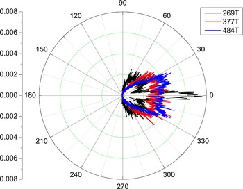
The angular distributions of the protons in the hole before and after they merge on the axis are given in Figure 5. We see that at t = 269T (black curve) the protons emitted from the two inner hole corners are confined to angles of 30°. The energetic (but low-density) protons in the axial direction are from TNSA. For the same reason the protons in the plasma bunch at later times are actually much better collimated, as can be seen in Figure 4. After the two jets collide and merge at t = 377T (red curve), the emission angle of the resulting bunch is smaller, even though the emission angles of the proton jets from the corners become wider as target protons are still being accelerated into the hole. The process continues until t = 484T (blue curve), when the hole structure is destroyed and the direction and profile of the corner jets become less clear. One can nevertheless see that the emission angle of the resulting proton jet actually become smaller.

Fig. 5. (Color online) Angular distributions of protons in the hole at t = 269T (black curve), t = 377T (red curve) and t = 484T (blue curve), respectively.
The TNSA protons ejected from planar targets are normal to the back surface. With the holed target, the proton trajectories are significantly modified, as shown in Figure 6. It can be seen that typical protons are focused towards the propagation axis, and the resulting collimated proton bunch can propagate for a much longer distance without much change. This can be attributed to the particular configuration of the space-charge field near the hole-wall as well as to the neutralization of the proton jets by the low-energy thermal electrons in the hole. At much later times, the bunch expands slowly, as seen in Figure 4f. That is, it does not diverge rapidly as for targets with smooth planar or concave backsides (Okada et al., Reference Okada, Andreev, Mikado and Okubo2006; Liu et al., Reference Liu, Wu, Xie, Liu, Wang and Yu2008; Ma et al., Reference Ma, Sheng, Gu, Yu, Yin, Shao, Yu and Chang2009), since the space-charge field in the hole has a guiding effect in the formation and propagation of the bunch. This can be seen in Figure 7 for the transverse momentum P y of protons originated from the upper and lower corners, especially when they converge onto the axis. Figure 7a corresponds to Fig. 4(d), when the jets have not yet converged. We see that at that time the protons from the hole corners have larger transverse momentum, with a maximum of P y max ~ 0.07m pc. Fig. 7(b) shows that at t = 377T P y max decreases to 0.06m pc. At 484T, when the structure of the target has been destroyed and most of the protons have converged, we have P y max ~ 0.04m pc, which is nearly half that at 269T. That is, the protons become more and more aligned to the axis. Similar results are found for the target with densities of 4n c, 7n c, 20n c, etc. We find that the higher the initial density of the target is, the shorter the time for the protons to converge on the axis and the higher the density of the proton bunch. However, since there are many more protons originating from the hole corners of the higher density target, the proton bunch for the 20n c target is not as distinct as that for the 10n c target.

Fig. 6. (Color online) Typical proton trajectories near the hole bottom.

Fig. 7. Transverse momentum distributions of the protons at the time of t = 269T (a), t = 377T (b), and t = 484T (c), respectively.
3. EFFECT OF THE HOLE DIAMETER
In the proton acceleration process, appropriate laser and target parameters are crucial for the proton beam quality. In order to obtain high quality proton bunches, that is, bunches with high energy and density, and low divergence, etc., one can optimize these parameters. We now consider the effect of the hole diameter D, keeping the laser spot radius fixed at σ = 10λ0. The density distributions of the proton bunch for D = 4λ0 and D = 12λ0 at t = 377T are presented in Figures 8a and 8b, respectively. It can be seen that the larger the D, the longer the focal length and the longer the time needed for the protons to converge. For example, at 377T the bunch from the D = 4λ0 target has converged but that for D = 12λ0 has not converged. For the D = 4λ0 target most protons from the hole corners can cross the propagation axis and are not efficiently accelerated in the axial direction. Figure 8b shows that for the D = 12λ0 target almost all the protons from the hole corners are accelerated efficiently and focused onto the propagation axis, although the density is lower. Figure 9 gives the energy distribution of the protons in the hole for D = 4λ0 (black curve), D = 8λ0 (red curve), D = 12λ0 (blue curve) at t = 377T. It can be seen that protons from the target with the small hole are lower in number and have lower cutoff energy. From the fact that laser spot radius is ![]() here, we see that to obtain large proton current, the diameter of the hole should be about the laser spot radius. This is because for too-large diameter holes, the protons emitted from the corners need to propagate much longer distances and can thus become dispersed before they merge. The resulting bunch will then of low density and not well collimated. When the hole diameter is too small, the protons converge too early and just pass each other on the axis, since the cavity space-charge field favorable for merging and guiding of the bunch is further downstream.
here, we see that to obtain large proton current, the diameter of the hole should be about the laser spot radius. This is because for too-large diameter holes, the protons emitted from the corners need to propagate much longer distances and can thus become dispersed before they merge. The resulting bunch will then of low density and not well collimated. When the hole diameter is too small, the protons converge too early and just pass each other on the axis, since the cavity space-charge field favorable for merging and guiding of the bunch is further downstream.

Fig. 8. (Color online) The proton density distributions for D = 4λ0 (a) and D = 12λ0 (b) at t = 377T, in units of n c. The other parameters are the same as that in the other figures.

Fig. 9. (Color online) Energy spectra of the protons in the hole for D = 4λ0 (black curve), D = 8λ0 (red curve), D = 12λ0 (blue curve) at t = 377T. The other parameters are the same as that in the other figures.
4. SUMMARY
We have presented a scheme for obtaining collimated proton bunches from the interaction of an ultraintense laser pulse with a rear-holed target. Energetic electron and proton jets are generated from the inner hole corners and merge on the laser axis. The resulting quasi-neutral plasma bunch is well collimated and can propagate in the hole cavity for a long distance along the axis. It is shown that the density and current of the bunch can reach 8.76n c and 1.33 × 10¹² A/cm2, respectively, and that the bunch can propagate without divergence over a longer distance in the hole. The diameter of the hole is crucial to the quality of the proton bunch. To realize large proton current, itshould be near that of the laser spot.
ACKNOWLEDGMENTS
This work was supported by the National High-Tech ICF Committee, the National Natural Science Foundation of China (10505030, 10505031, 10576035, 10605038, 10835003, 10975185, and 10976031), the Science and Technology Development Foundation of the Chinese Academy of Engineering Physics (2006Z0202), and the National Basic Research Program of China (2007CB815105, 2008CB717806 and 2009GB105005). We also acknowledge the support of the National University of Defense Technology (NUDT) Foundation (JC09-02-08) and the NUDT High Performance Computer Research Center. Y. Y. Ma acknowledges the support of the JSPS and CORE of Utsunomiya University, Japan.