I. INTRODUCTION
An axially slotted cylinder coated with homogeneous and inhomogeneous coatings have been investigated by several authors [Reference Hurd1–Reference Tyras20] due to their many important technical applications. These coated slotted cylinders have applications in the fields of wireless communications, radar and satellite communications, space vehicles, and aircrafts. These slotted cylinders are easy to fabricate, lightweight, and their gain properties can be controlled easily. The radiation characteristics of an axially slotted cylinder with a dielectric coating has been studied by Hurd [Reference Hurd1]. The fields produced by an arbitrary slot on a conducting cylinder coated with dielectric and magnetic layers have been obtained by Wait and Mientka [Reference Wait and Mienteka2]. They studied that thin magnetic coating gives rise to more trapped peripheral surface waves as compared with thin dielectric coating. The radiation properties of a dielectric-coated axially slotted cylinder has been investigated by Shafai [Reference Shafai3]. Knop has derived an expression for the admittance of an axial slot on a dielectric-coated conducting cylinder [Reference Knop4]. Mushref has analyzed the gain characteristics of a dielectric-coated axially slotted cylinder with two arbitrary slots [Reference Mushref5, Reference Mushref6].
The effects of various plasma coatings upon the radiation characteristics of an axially slotted cylinder have been studied by numerous authors [Reference Rusch7–Reference Chen and Cheng9]. The influences of slot width, plasma frequency, and plasma coating thickness upon the field patterns of a finite axial slot on a cylinder coated with a homogeneous and uniform plasma layer have been investigated by Rusch [Reference Rusch7]. He studied that if the operating frequency is below the plasma frequency, then less energy is guided peripherally and the field pattern is mostly broadside-directed. Marchin and Tyras [Reference Marchin and Tyras8] have studied the radiated field patterns of an axially slotted cylinder coated with a magnetoplasma layer. They also analyzed that the reversal of the orientation of the magneto-static field causes a shift of the pattern to a mirror image position. An analysis about the radiation properties of an anisotropic plasma-coated axially slotted cylinder is carried out by Chen and Cheng [Reference Chen and Cheng9]. Wu and Ren [Reference Wu and Ren10] have investigated the radiation properties of an axially slotted circular cylinder coated with an anisotropic dielectric layer.
An elliptic cylinder having an axial slot and coated with dielectric and metamaterial layers have been studied by some authors [Reference Richmond11–Reference Hamid13]. Hamid concluded that a metamaterial coating enhances the forward direction (FD) gain as compared with a conventional dielectric coating [Reference Hamid12]. The gain properties of a dielectric-coated axially slotted cylinder embedded in a metamaterial background has been investigated by Awan [Reference Awan14]. The effects of two different dielectric, magnetic, and metamaterial coatings upon the gain pattern have been considered in [Reference Awan15]. The radiation characteristics of a chiral-coated slotted cylinder has been studied by Mahmoud [Reference Mahmoud16] and Awan [Reference Awan17]. Mahmoud has investigated the radiation properties of chiral-coated longitudinal and circumferential slots with the free space background. The effects of various chiral and chiral nihility coatings and chiral background media upon the gain pattern of a chiral-coated axially slotted cylinder have been studied by Awan. Recently, Awan has extended the proposed theory in [Reference Awan17] to the bi-isotropic coatings and bi-isotropic background media in [Reference Awan18]. He studied that a strong bi-isotropic coating with the free space background significantly enhances the gain in the FD. He also concluded that a strong Tellegen coating guided most of the slot-radiated field toward rear side of the cylinder.
The radiation characteristics of an axial slot coated with an inhomogeneous layer has been investigated by Yeh and Kaprielian [Reference Yeh and Kaprielian19] and Tyras [Reference Tyras20]. It is concluded that the radiation spreads out more toward the rear side of the cylinder for a thicker inhomogeneous coating [Reference Yeh and Kaprielian19]. Valagiannopoulos has analyzed the line source scattering by a cylindrical microstrip with radially inhomogeneous substrate. He has taken a substrate whose permittivity follows a power law [Reference Valagiannopoulos21]. The effects of decreasing permittivity profiles of inhomogeneous coatings upon the gain pattern have not been explored previously. The influences of coating thickness upon the gain pattern also have not been considered. Likewise, no one has considered the effects of inhomogeneity parameters of these types of inhomogeneous coatings upon the forward and backward direction (BD) gains. These effects are investigated in the current study.
In this paper, an infinite axial slot is engraved on a perfectly conducting cylinder. This axially slotted cylinder is coated with two specific types of inhomogeneous coatings. These inhomogeneous coatings are taken to be non-magnetic and have decreasing permittivity profiles. It should be noted that such type of inhomogeneous coatings can be artificially realized by using an idea of cylindrically stratified layered media. Recent advancements in fabrication technology has made it possible to realize such type of inhomogeneous coatings. The effects of various parameters of these inhomogeneous coatings upon the gain pattern of an axially slotted cylinder with the free space background have been considered. It is shown that for these inhomogeneous coatings with specific geometrical and parametrical configurations, the gain in the FD can be enhanced significantly which is an important result. Such type of enhanced gains in the FD are used in point-to-point communications.
II. GAIN OF AN AXIALLY SLOTTED CYLINDER WITH AN INHOMOGENEOUS COATING
An infinite length hollow circular cylinder made up of perfectly electric conducting material is considered. It has an axial direction parallel to the z-axis and the radius of cylinder is taken to be a. A narrow infinite axial slot having slot width of ϕ o is engraved in this cylinder. This slotted cylinder is coated with specific types of inhomogeneous coatings. These coatings are assumed to be non-magnetic having relative permeability of unity. The inhomogeneous nature of coatings are associated with the relative permittivity and exist only for a radial variable ρ of a usual cylindrical coordinates, i.e. ε r (ρ). The outer radius of inhomogeneous coating is taken to be b. This axially slotted cylinder with an inhomogeneous coating is placed in a free space background, which is characterized by permittivity ε o and permeability μ o . The geometry of the problem is shown in Fig. 1.

Fig. 1. Geometry of an inhomogeneous-coated axially slotted cylinder.
It is assumed that axial slot is narrow and has a constant electric field distribution E a , which is maintained across the slot for − ϕ o /2 ≤ ϕ ≤ ϕ o /2. This slot excitation can be expanded in a complex Fourier series using [Reference Marchin and Tyras8, Reference Yeh and Kaprielian19] and is given below:
 $$E_\phi = \displaystyle{{E_a} \over \pi} \sum\limits_{n = - \infty} ^{n = + \infty} \displaystyle{{\sin (n\phi _o/2)} \over n}e^{in\phi}. $$
It is obvious that given source of excitation as given by equation (1) is a purely transverse electric type. For this excitation, we have axial component of the magnetic field H z and ϕ-component of the electric field E ϕ as non-zero. Therefore, we are interested in the z-component of magnetic field and ϕ-component of electric field in the inhomogeneous coating and background medium.
In the inhomogeneous coating region defined by a ≤ ρ ≤ b, the electric and magnetic field vectors, i.e.
 ${\bf E}^c$
and
${\bf E}^c$
and
 ${\bf H}^c$
satisfy the following Maxwell's equations:
${\bf H}^c$
satisfy the following Maxwell's equations:
 $$\nabla \times {\bf E}^c = i\omega \mu _o{\bf H}^c,$$
 $$\nabla \times {\bf H}^c = - i\omega {\rm \epsilon} _o{\rm \epsilon} _r(\rho ){\bf E}^c.$$
Using these above equations (2) and (3) and expanding them in cylindrical coordinates, it can be shown that the axial component of magnetic field vector
 $H_z^c $
satisfy the following equation [Reference Yeh and Kaprielian19, Reference Tyras20]:
$H_z^c $
satisfy the following equation [Reference Yeh and Kaprielian19, Reference Tyras20]:
 $$\eqalign{& \displaystyle{1 \over \rho} \displaystyle{\partial \over {\partial \rho}} \left[ {\rho \displaystyle{{\partial H_z^c} \over {\partial \rho}}} \right] - \displaystyle{1 \over {{\rm \epsilon} _r(\rho )}}\displaystyle{{\partial {\rm \epsilon} _r(\rho )} \over {\partial \rho}} \displaystyle{{\partial H_z^c} \over {\partial \rho}} + \displaystyle{1 \over {\rho ^2}}\displaystyle{{\partial ^2H_z^c} \over {\partial \phi ^2}} + k_o^2 {\rm \epsilon} _r(\rho )H_z^c \cr & = 0.}$$
At this stage, it is appropriate to seek the solution of the form as given below:
 $$H_z^c (\rho, \phi ) = \sum\limits_{n = - \infty} ^{n = + \infty} W_n(\rho )e^{in\phi}. $$
Using this solution of equation (5) in equation (4), we get the following differential equation:
 $$\eqalign{ & W_n{^{\prime \prime}} (\rho ) + \left[ {\displaystyle{1 \over \rho} - \displaystyle{{{{{\rm \epsilon} ^{\prime}}}_r(\rho )} \over {{\rm \epsilon} _r(\rho )}}} \right]W_n^{\prime} (\rho ) + \left[ {k_o^2 {\rm \epsilon} _r(\rho ) - \displaystyle{{n^2} \over {\rho ^2}}} \right]W_n(\rho )\cr & = 0.}$$
where
 $k_o = \omega \sqrt {\mu _o{\rm \epsilon} _o} $
is the free space wavenumber. The prime sign (′) shows the differentiation with respect to the ρ. It is clear from equation (6) that once the solution of W
n
(ρ) for a particular permittivity profile ε
r
(ρ) is known, then the complete solution of an axial magnetic field can be found from equation (5). We are interested in permittivity profile, which is decreasing with respect to an increase of ρ. This means that ε
r
(a) is greater than ε
r
(b). This profile represents an electrically dense medium closer to source of excitation and an electrically rarer medium at the inhomogeneous coating–air interface. Such type of profiles are considered by Burman [Reference Burman22] for wave propagation in cylindrically stratified media.
$k_o = \omega \sqrt {\mu _o{\rm \epsilon} _o} $
is the free space wavenumber. The prime sign (′) shows the differentiation with respect to the ρ. It is clear from equation (6) that once the solution of W
n
(ρ) for a particular permittivity profile ε
r
(ρ) is known, then the complete solution of an axial magnetic field can be found from equation (5). We are interested in permittivity profile, which is decreasing with respect to an increase of ρ. This means that ε
r
(a) is greater than ε
r
(b). This profile represents an electrically dense medium closer to source of excitation and an electrically rarer medium at the inhomogeneous coating–air interface. Such type of profiles are considered by Burman [Reference Burman22] for wave propagation in cylindrically stratified media.
A) Inhomogeneous coating with profile 1
In the first case, the decreasing permittivity profile of an inhomogeneous coating is given below:
 $${\rm \epsilon} _{r1}(\rho ) = \displaystyle{1 \over {k_o^2 {[\alpha + \beta \rho ]}^2}},$$
where α and β are independent of ρ and taken to be positive real numbers with α ≠ 0 and β ≠ 0. Substituting equation (7) in equation (6) with ε
r1(ρ) = ε
r
(ρ), it can be shown from Buramn [Reference Burman22] that equation (6) can be reduced to a standard hypergeometric equation. Using equation (5), the complete solution of an axial component of the magnetic field
 $H_z^c $
can be found. Likewise, the ϕ component of the electric field
$H_z^c $
can be found. Likewise, the ϕ component of the electric field
 $E_\phi ^c $
inside the inhomogeneous coating can be found from Maxwell's equation, i.e.
$E_\phi ^c $
inside the inhomogeneous coating can be found from Maxwell's equation, i.e.
 $E_\phi ^c = ( - i/\omega {\rm \epsilon} _o{\rm \epsilon} _{r1}(\rho ))\partial H_z^c /\partial \rho $
. After some manipulations, they can be written as
$E_\phi ^c = ( - i/\omega {\rm \epsilon} _o{\rm \epsilon} _{r1}(\rho ))\partial H_z^c /\partial \rho $
. After some manipulations, they can be written as
 $$H_z^c = \sum\limits_{n = - \infty} ^{n = + \infty} [C_nA_1(\rho ) + D_nB_1(\rho )]e^{in\phi}, $$
 $$E_\phi ^c = - ik_o\eta _o(\alpha + \beta \rho )^2\sum\limits_{n = - \infty} ^{n = + \infty} [C_nA_1 ^{\prime} (\rho ) + D_nB_1^{\prime} (\rho )]e^{in\phi}, $$
 $$A_1^{\prime} (\rho ) = \displaystyle{\partial \over {\partial \rho}} A_1(\rho) = \displaystyle{\partial \over {\partial \rho}} \left[ {U{(\rho )}_2F_1\left( {\mu, \lambda, \tau, - \displaystyle{\beta \over \alpha} \rho} \right)} \right],$$
 $$B_1^{\prime} (\rho ) = \displaystyle{\partial \over {\partial \rho}} B_1(\rho ) = \displaystyle{\partial \over {\partial \rho}} [U(\rho )Y_1(\rho )],$$
 $$U(\rho ) = \beta ^{\tau /2}(1/\alpha )^{\mu + \lambda + 1/2}\rho ^{\tau - 1/2}(\alpha + \beta \rho )^{\mu + \lambda - \tau - 1/2},$$
 $$\eqalign{Y_1(\rho ) \;=\; & _2F_1\left( {\mu, \lambda, \tau, - \displaystyle{\beta \over \alpha} \rho} \right){\rm ln}\left( { - \displaystyle{\beta \over \alpha} \rho} \right) + \sum \limits_{k = 0}^\infty \left[ {\displaystyle{{{(\mu )}_k{(\lambda )}_k} \over {k!(\tau )_k}}{\left( { - \displaystyle{\beta \over \alpha} \rho} \right)}^k} \right. \cr & \left. { \{ \psi (\mu \;+\; k) \;+\; \psi (\lambda + k) \;-\; \psi (1 + k) \;-\; \psi (\tau + k)\}} \right] \cr & \quad - \sum\limits_{k = 1}^{\tau - 1} \displaystyle{{(\tau - 1)!(k - 1)!} \over {(\tau - k - 1)!(1 - \mu )_k{(1 - \lambda )}_k}}\left( { - \displaystyle{\beta \over \alpha} \rho} \right)^{ - k},}$$
 $$\mu = (1/2)\left[ {\sqrt {1 - 4\beta ^{ - 2}} + 2\sqrt {n^2 - \beta ^{ - 2} + 1} + \tau} \right],$$
 $$\lambda = (1/2)\left[ {\sqrt {1 - 4\beta ^{ - 2}} - 2\sqrt {n^2 - \beta ^{ - 2} + 1} + \tau} \right],$$
 $$\tau = 1 + 2 \vert n \vert, $$
where 2 F 1(·), ψ(·), and (a) k are the hypergeometric function, the psi or digamma function, and Pochhammer's symbol, respectively [Reference Olver23]. Also | · | shows the modulus function. It is important to note that if β = 0 then equations (8)–(16) can not be directly used for the field solutions. This is because the field solutions do not exist in this case. For this particular case, we have ε r1 = ε r = 1/(k o α)2 and we use this profile in equation (6). After using this profile in equation (6), it can be shown that the field solutions become similar in forms as given by equations (18)–(22) on the next page. In this special case of β = 0, it is needed to use ζ = 0 and ξ = 1/α in equations (18)–(22) for the field solutions. On the other hand, if α = 0 then from equation (7) it is found that ε r1(ρ) = u 2/ρ 2 with u 2 = 1/(k o β)2. Using ε r1(ρ) = ε r (ρ) = u 2/ρ 2 in equation (6) and after some manipulations, it can be shown from [Reference Burman24] that field solutions can be expressed in terms of simple algebraic functions. The coefficients C n and D n are unknowns and needed to be determined.
B) Inhomogeneous coating with profile 2
In the second case, the specific profile ε r2(ρ) of an inhomogeneous coating is given as
 $${\rm \epsilon} _{r2}(\rho ) = \displaystyle{1 \over {k_o^2}} \left( {\displaystyle{\xi \over {\rho ^\zeta}}} \right)^2,$$
where ξ and ζ are independent of ρ and are positive real numbers with ζ ≠ 1. Using the same procedure as outlined in Section II.A, the z-component of magnetic field and ϕ-component of electric field inside the inhomogeneous coating are given as
 $$H_z^c = \xi \sum\limits_{n = - \infty} ^{n = + \infty} [F_nA_2(\rho ) + G_nB_2(\rho )]e^{in\phi}, $$
 $$E_\phi ^c = - \displaystyle{{ik_o\eta _o} \over {\xi \rho ^{ - 2\zeta}}} \sum\limits_{n = - \infty} ^{n = + \infty} [F_nA_2^{\prime} (\rho ) + G_nB_2 ^{\prime} (\rho )]e^{in\phi}, $$
 $$A_2 ^{\prime} (\rho ) = \displaystyle{\partial \over {\partial \rho}} A_2(\rho ) = \displaystyle{\partial \over {\partial \rho}} [\rho ^{ - \zeta} J_\nu (\gamma \rho ^{1 - \zeta} )],$$
 $$B_2^{\prime} (\rho ) = \displaystyle{\partial \over {\partial \rho}} B_2(\rho ) = \displaystyle{\partial \over {\partial \rho}} [\rho ^{ - \zeta} Y_\nu (\gamma \rho ^{1 - \zeta} )],$$
 $$\gamma = \displaystyle{\xi \over {1 - \zeta}}, \quad \nu = \displaystyle{{\sqrt {n^2 + \zeta ^2}} \over {1 - \zeta}}, $$
where η o is the intrinsic impedance of free space. It should be noted that if ζ = 1 then the arguments of Bessel functions given in equations (20)–(21) become infinite. Therefore, ζ = 1 is not allowed for the proposed formulation in this subsection. On the other hand, if ζ = 1/2 then the profile given by equation (17) and field solutions of equations (18)–(22) have the same forms as considered by Yeh and Kaprielian [Reference Yeh and Kaprielian19]. This is further discussed in the section of numerical results.
Likewise, the axial component of the magnetic field and the ϕ-component of the electric field, i.e.
 $H_z^b $
,
$H_z^b $
,
 $E_\phi ^b $
in the background region having ρ ≥ b can be written as
$E_\phi ^b $
in the background region having ρ ≥ b can be written as
 $$H_z^b = \sum\limits_{n = - \infty} ^{n = + \infty} K_nH_n^{(1)} (k_b\rho )e^{in\phi}, $$
 $$E_\phi ^b = - i\eta _b\sum\limits_{n = - \infty} ^{n = + \infty} K_n\dot H_n^{(1)} (k_b\rho )e^{in\phi}, $$
where
 $H_n^{(1)} ( \cdot )$
is the nth-order Hankel function of first kind and represents an outward traveling wave solution. An overhead dot
$H_n^{(1)} ( \cdot )$
is the nth-order Hankel function of first kind and represents an outward traveling wave solution. An overhead dot
 $\cdot$
also shows the derivative with respect to the whole argument. The factor η
b
represents the intrinsic impedance of background medium. The wavenumber in the background region is given by
$\cdot$
also shows the derivative with respect to the whole argument. The factor η
b
represents the intrinsic impedance of background medium. The wavenumber in the background region is given by
 $k_b = \omega \sqrt {\mu _b{\rm \epsilon} _b} $
. In this case, μ
b
and ε
b
represent the permeability and the permittivity of the background medium. The coefficient K
n
is unknown and needed to be determined.
$k_b = \omega \sqrt {\mu _b{\rm \epsilon} _b} $
. In this case, μ
b
and ε
b
represent the permeability and the permittivity of the background medium. The coefficient K
n
is unknown and needed to be determined.
It is known that the unknown coefficients C n , D n or F n , G n , and K n can be found by applying the tangential boundary conditions at cylindrical interfaces ρ = a and ρ = b. Once these unknown coefficients are known, we can find the fields in each region using equations (8)–(16) or equations (18)–(22) and equations (23) and (24). In order to find the fields in the background region, the coefficient K n is of an interest. Using tangential boundary conditions, the unknown coefficient K n for both the inhomogeneous coatings can be written in the following form:
 $$\eqalign{& K_n = i \cr & \displaystyle{{(E_a/\pi )(\sin (n\phi _o/2)/n)P_j} \over {\eta _b({\rm \epsilon} _{rj}(b)/{\rm \epsilon} _{rj}(a))\dot H_n^{(1)} (k_bb)Q_j - (1/k_o)(\eta _o/{\rm \epsilon} _{rj}(a))H_n^{(1)} (k_bb)R_j}}},$$
 $$P_j = A_j(b)B_j^{\prime} (b) - A_j^{\prime} (b)B_j(b),$$
 $$Q_j = A_j(b)B_j^{\prime} (a) - A_j^{\prime} (a)B_j(b),$$
 $$R_j = A_j^{\prime} (b)B_j^{\prime} (a) - A_j^{\prime} (a)B_j^{\prime} (b),$$
where j = 1, 2. Here j = 1 corresponds to K n coefficient for profile 1, whereas j = 2 corresponds to K n coefficient for profile 2. Once the coefficient K n is known then the fields in the background region become known.
The gain of an axially slotted cylinder with an inhomogeneous coating is a quantity of an interest for the present study. This is because the gain pattern provides significant information about the directional characteristics of a slotted cylinder. In the present study, a gain pattern is a plot of gain versus angle ϕ. By investigating the effects of various parameters upon the gain pattern, it can be seen how the gain can be enhanced or diminished in a certain direction. Therefore, the study of a gain pattern is of crucial importance. For example, high gains are preferred in point-to-point communications. This gain of an axially slotted cylinder covered with an inhomogeneous coating can be found using [Reference Richmond11, Reference Awan15, Reference Awan17, Reference Awan18] and given below:
 $$G(\phi ) = \displaystyle{{\sum\nolimits_{n = - \infty} ^{n = + \infty} { \vert ( - i)^nK_ne^{in\phi} \vert ^2}} \over {\sum\nolimits_{n = - \infty} ^{n = + \infty} { \vert K_n \vert ^2}}}. $$
III. NUMERICAL RESULTS
The effects of inhomogeneous coatings upon the gain properties of an axially slotted cylinder embedded in the free space background have been shown and discussed in this section. Two types of inhomogeneous coatings with decreasing permittivity profiles are considered. The parameters for both profiles are so chosen that maximum and minimum values of inhomogeneous permittivity ε rj (ρ) lies in the range 10≤ ε rj (ρ) ≤0.001 with j = 1, 2. The operating free space wavelength is taken to be 0.1 m with applied excitation of unity, i.e. E a = 1. The width of an axial slot is assumed to be ϕ o = π/100 rads, which ensures a constant electric field across the slot. The gain for profile 1 is computed using equation (29) and equations (25)–(28) with (7)–(16), whereas for profile 2, the gain is calculated using equation (29) and equations (25)–(28) with (17)–(22). Figures 4–8 deal with the gains of inhomogeneous coating of profile 1, whereas Figs 9–13 are representative of gains related to inhomogeneous coating of profile 2. It can be shown that proposed results are in good agreement with [Reference Hurd1, Reference Wait and Mienteka2, Reference Shafai3, Reference Mushref5, Reference Yeh and Kaprielian19] for homogeneous coating as well provided that if we take β = 0 for profile 1 and ζ = 0 for profile 2 with specific chosen values of α and ξ, which is discussed below. It is noted that for all figures, an inner radius a is taken to be 0.25λ o , whereas an outer radius b of an inhomogeneous coating is considered to be 0.5λ o except for Figs 2, 3, 6, and 11. In Figs 6 and 11, radius b is variable.

Fig. 2. (a) The gain for profile 1 having β = 0,
 $\alpha = 1/(k_o\sqrt {4\ln (1.5)} )$
and its comparison with [Reference Yeh and Kaprielian19]. (b) The gain for profile 2 having ζ = 0,
$\alpha = 1/(k_o\sqrt {4\ln (1.5)} )$
and its comparison with [Reference Yeh and Kaprielian19]. (b) The gain for profile 2 having ζ = 0,
 $\xi = k_o\sqrt {4\ln (1.5)} $
and its comparison with [Reference Yeh and Kaprielian19].
$\xi = k_o\sqrt {4\ln (1.5)} $
and its comparison with [Reference Yeh and Kaprielian19].

Fig. 3. The gain of an axially slotted cylinder coated with an inhomogeneous profile 2 having ζ = 1/2,
 $\xi = \sqrt {4k_o} $
and its comparison with [Reference Yeh and Kaprielian19].
$\xi = \sqrt {4k_o} $
and its comparison with [Reference Yeh and Kaprielian19].

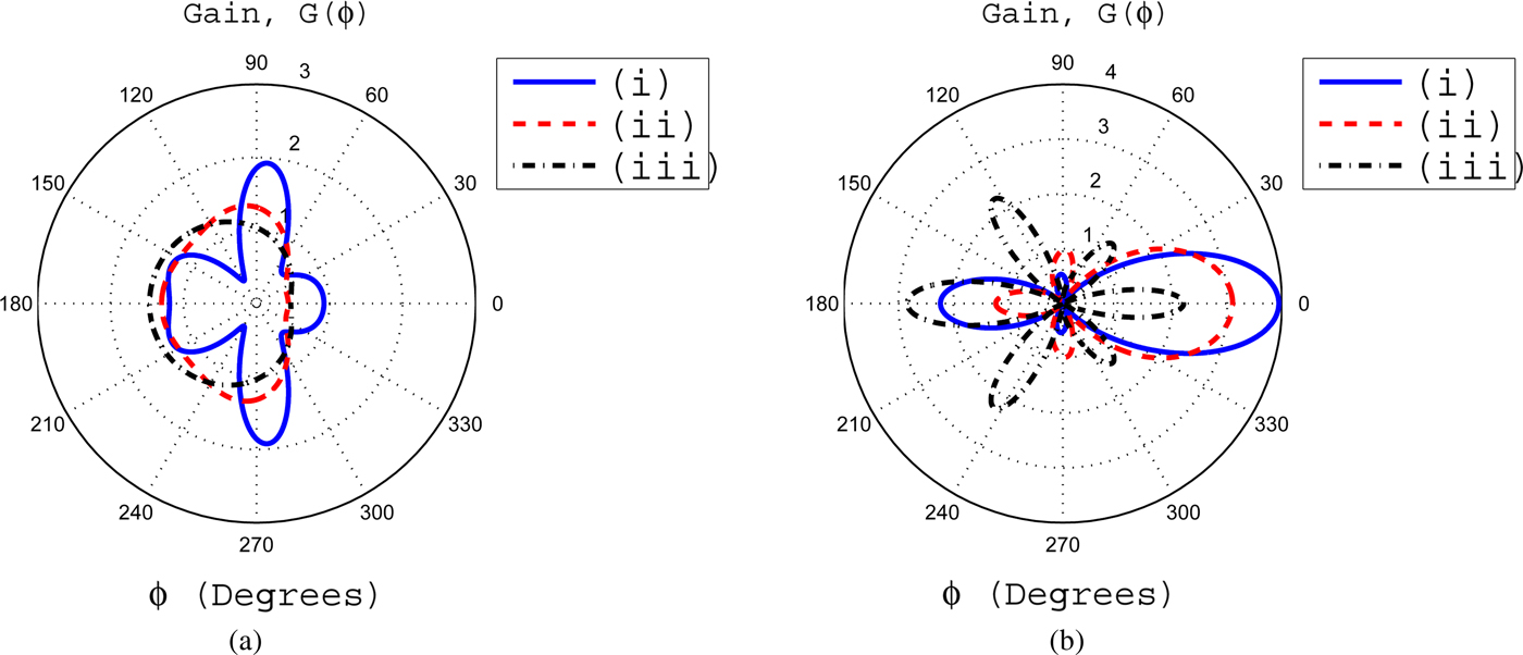
Fig. 4. (a) The gain for β = 0.3 with (i) α = 0.03, (ii) α = 0.045, and (iii) α = 0.09. (b) The gain for β = 0.6 for variable values of α, i.e. (i) α = 0.03, (ii) α = 0.045, (i) α = 0.09.

Fig. 5. (a) The effects of α upon gain pattern with β = 1 (i) α = 0.03, (ii) α = 0.045, and (iii) α = 0.09. (b) The gain pattern for fixed value of α = 0.005 with (i) β = 0.01, (ii) β = 0.03 and (iii) β = 0.06.
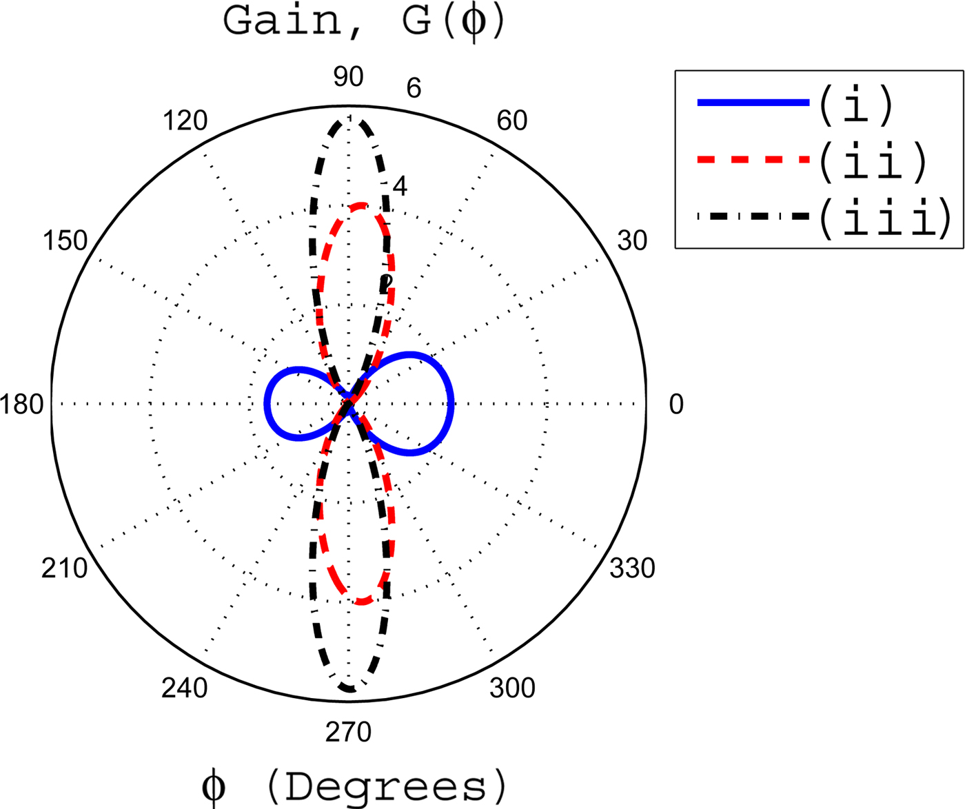
Fig. 6. The influences of coating thickness upon the gain pattern. In this case, the inner radius a is fixed at 0.25λ o . The inhomogeneous coating with profile 1 has parameters of α = 0.01 and β = 0.3. The coating thickness is Δ = b−a. Here we have coating thicknesses (i) Δ = 0.25λ o , (ii) Δ = 0.5λ o , and (iii) Δ = 0.75λ o .

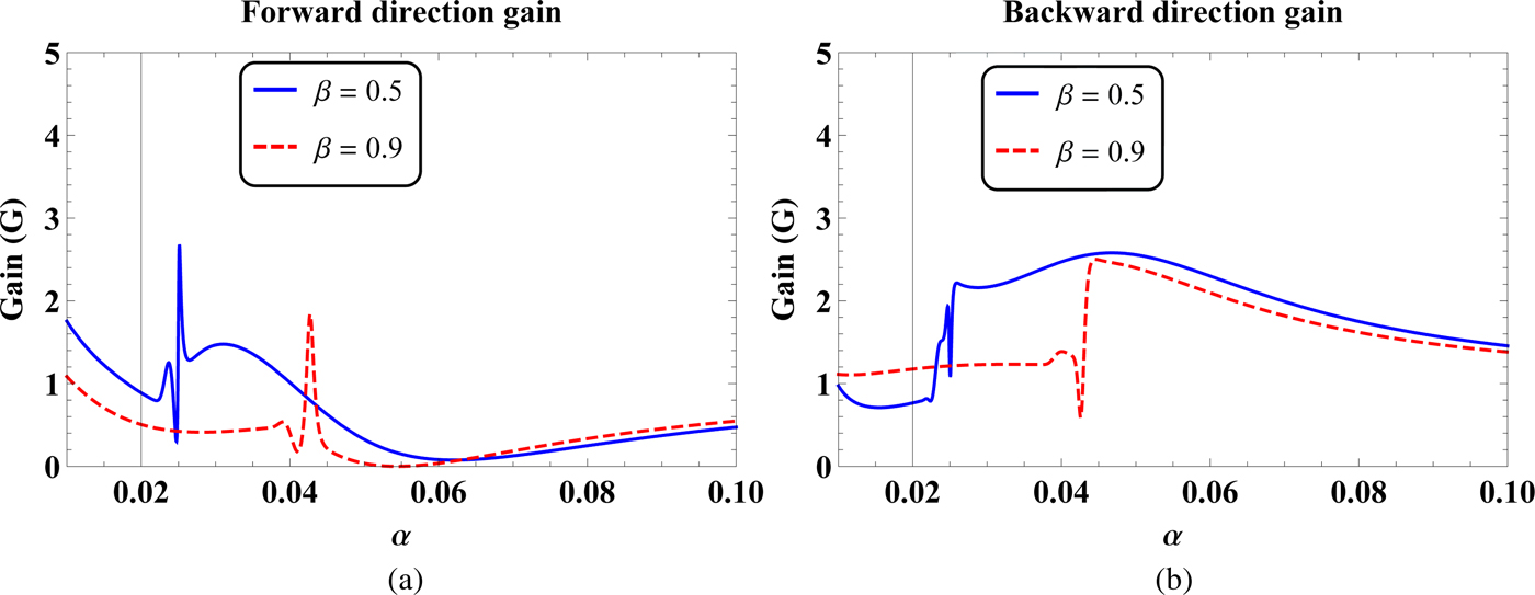
Fig. 7. The (a) forward direction and (b) backward direction gains as a function of parameter α for β = 0.5 and 0.9.
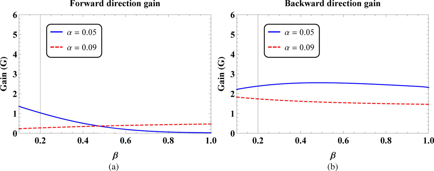
Fig. 8. The (a) forward direction and (b) backward direction gains as a function of parameter β for different values of α, i.e. α = 0.05 and 0.09.
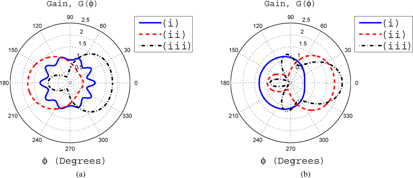
Fig. 9. (a) The gain pattern for ζ = 2.6 with (i) ξ = 0.001, (ii) ξ = 0.0035, and (iii) ξ = 0.007. (b) The gain pattern for ζ = 2.8 for different values of ξ and they are (i) ξ = 0.001, (ii) ξ = 0.0035, and (iii) ξ = 0.007.
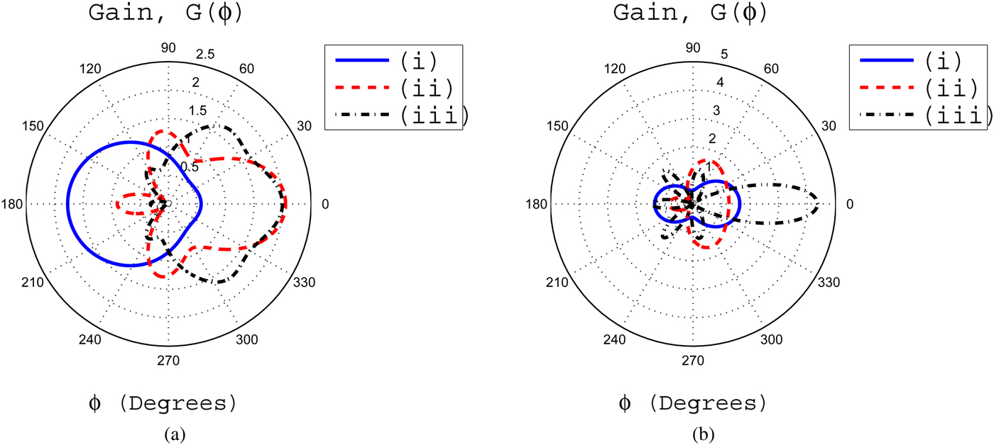
Fig. 10. (a) The effects of ξ upon gain pattern with ζ = 3 (i) ξ = 0.001, (ii) ξ = 0.0035, and (iii) ξ = 0.007. (b) The gain pattern for fixed value of ξ = 0.0051 with (i) ζ = 2.6, (ii) ζ = 2.8, and (iii) ζ = 3.
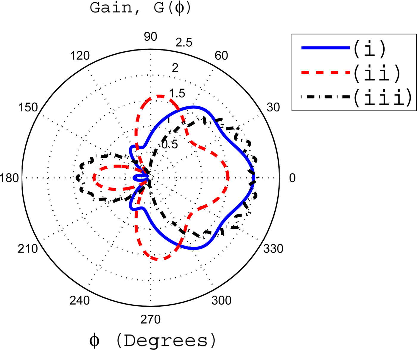
Fig. 11. The effects of coating thickness upon the gain pattern. In this case, the inner radius a is fixed at 0.25λ o . The inhomogeneous coating with profile 2 has parameters of ζ = 3 and ξ = 0.007. The coating thickness are taken to be (i) Δ = 0.25λ o , (ii) Δ = 0.5λ o , and (iii) Δ = 0.75λ o .

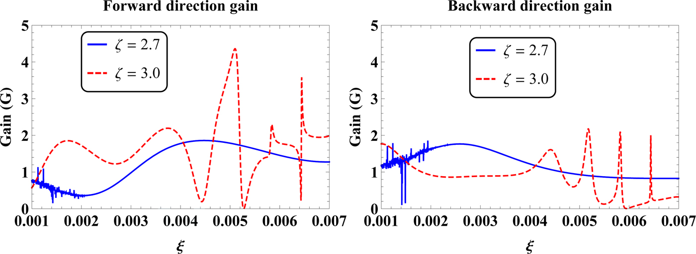
Fig. 12. The (a) forward direction and (b) backward direction gains as a function of parameter ξ for various values of ζ, i.e. ζ = 2.7 and 3.
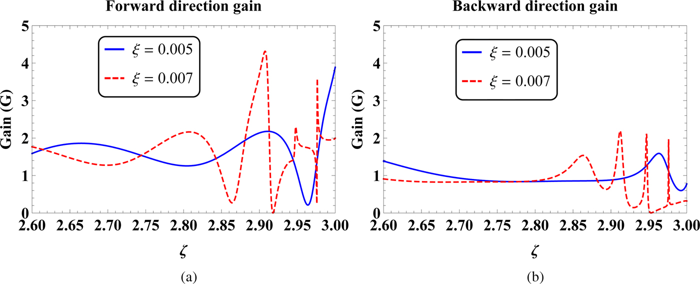
Fig. 13. The (a) forward direction and (b) backward direction gains as a function of parameter ζ for ξ = 0.005 and 0.007.
In order to validate the accuracy of the proposed formulations, the results based on the proposed formulations are compared with the previous work of Yeh and Kaprielian [Reference Yeh and Kaprielian19] for homogeneous and inhomogeneous coatings. In case of homogeneous coating, it is assumed that a = (1/π)λ
o
, b = (1.5/π)λ
o
, ϕ
o
= π/100 rads, and the relative permittivity of a homogeneous coating is 4ln(1.5) = 1.6219. These parameters have been adopted from reference [Reference Yeh and Kaprielian19]. From equations (7) and (17), it is obvious that if β = 0 for profile 1 and ζ = 0 for profile 2, then both coating profiles become homogeneous. These two homogeneous coating profiles also become same provided that if α = 1/ξ. Now by assuming
 $\alpha = 1/\xi = 1/k_o\sqrt {4\ln (1.5)} $
for both profiles, it is noticed that the relative permittivity become same as adopted in [Reference Yeh and Kaprielian19]. Using these above information in the proposed formulation, it is shown in Fig. 2 that gains of both homogeneous profiles are consistent with [Reference Yeh and Kaprielian19]. For an inhomogeneous coating, it is already discussed in Section II.B that if we take ζ = 1/2 for profile 2, then this profile become similar in form as considered in [Reference Yeh and Kaprielian19]. Now using ζ = 1/2,
$\alpha = 1/\xi = 1/k_o\sqrt {4\ln (1.5)} $
for both profiles, it is noticed that the relative permittivity become same as adopted in [Reference Yeh and Kaprielian19]. Using these above information in the proposed formulation, it is shown in Fig. 2 that gains of both homogeneous profiles are consistent with [Reference Yeh and Kaprielian19]. For an inhomogeneous coating, it is already discussed in Section II.B that if we take ζ = 1/2 for profile 2, then this profile become similar in form as considered in [Reference Yeh and Kaprielian19]. Now using ζ = 1/2,
 $\xi = \sqrt {4k_o} $
, a = (0.5/π)λ
o
, b = (2/π)λ
o
, and ϕ
o
= π/100 rads in equations (17)–(22), it is shown in Fig. 3 that the gain become same as considered in Yeh and Kaprielian for a relatively thicker inhomogeneous coating. On the other hand, an inhomogeneous profile given by equation (7) in Section II.A is quite different and can not be compared with the work of Yeh and Kaprielian for any value of α and β. This is because the considered inhomogeneous profile 1 has ρ
−2 dependency, whereas the profile considered in [Reference Yeh and Kaprielian19] has ρ
−1 dependency. That is why, the profile 1 is not considered in Fig. 3 for the comparative study.
$\xi = \sqrt {4k_o} $
, a = (0.5/π)λ
o
, b = (2/π)λ
o
, and ϕ
o
= π/100 rads in equations (17)–(22), it is shown in Fig. 3 that the gain become same as considered in Yeh and Kaprielian for a relatively thicker inhomogeneous coating. On the other hand, an inhomogeneous profile given by equation (7) in Section II.A is quite different and can not be compared with the work of Yeh and Kaprielian for any value of α and β. This is because the considered inhomogeneous profile 1 has ρ
−2 dependency, whereas the profile considered in [Reference Yeh and Kaprielian19] has ρ
−1 dependency. That is why, the profile 1 is not considered in Fig. 3 for the comparative study.
The effects of various parameters of inhomogeneous coating of profile 1 upon gain patterns have been shown in Figs 4 and 5. It is observed from Fig. 4(a) that for β = 0.3 and α = 0.03, most of the radiated field from the slot exists at front side of the cylinder. The gain has a maximum value of 2 at ϕ = 0°. It is noticed that the gain at ϕ = 0° is taken to be the FD gain because the slot is centered at this angle. On the other hand, the gain at ϕ = 180° is considered to be the BD gain. It is seen from Fig. 4(a) that as the value of α increases, the most of radiated field from the slot is guided toward rear side of the cylinder through an inhomogeneous coating. This results in a significant decrease of radiated field in the FD. If the value of β increases to 0.6 for α = 0.03, it is noticed that the gains in the FD and BD reduce as compared with the corresponding gains for β = 0.3 and α = 0.03. This decrease in gains is compensated by an increase in gains at angles closer to 90 and 270°. This is shown in Fig. 4(b). If the value of α further increases, then the overall gain pattern shifts toward rear side of the cylinder.
In Fig. 5(a), we have β = 1, whereas α is variable. It is seen that as the value of β becomes unity for α = 0.03, a significant decrease in FD and BD gains is observed as compared with the respective gains for β = 0.3 and α = 0.03. This decrease in gains results in a significant increase of gains at angles 90 and 270° and approaches to a gain value of 2. If for β = 1, we increase α from 0.03 to 0.045 and 0.09, it is observed that overall gain pattern shifts toward rear side of the cylinder. In Fig. 5(b), an important result with reference to enhancement of FD gain is observed for α = 0.005 and β = 0.01. In this case, the FD gain becomes 4. Such type of high gains in the FD are used in point-to-point communications. If we further increase the value of β, the FD gain decreases and is obvious from Fig. 5(b). Figure 6 deals with the effects of coating thickness upon the gain pattern for some fixed values of inhomogeneity parameters α and β. For a coating thickness of Δ = 0.25λ o , the FD gain is greater than the BD gain. If the coating thickness is increased to a value of Δ = 0.5λ o , the gains in the FD and BD become negligible and enhanced gains of nearly four are observed at angles closer to 90 and 270°. If the coating thickness is further increased to 0.75λ o , then a significant enhancement in gains at angles 90 and 270° with nearly zero gains in the FD and BD are observed. Thus, it can be concluded that for specific values of α and β, an increase in coating thickness enhances the gains at angles closer to 90 and 270°. This increase in coating thickness also makes the FD and BD gains negligible.
It is clear from the geometrical configuration of the problem that the slot is centered at ϕ = 0°. Therefore, the maximum radiated field from the slot is expected to present at this angle. Some of the radiated field from the slot is guided toward rear side of the cylinder through the inhomogeneous coating. The rest of the radiated field from the slot is penetrated into the background through inhomogeneous coating–background interface. For a homogeneous dielectric coating, it is expected that the minimum field from the slot is guided toward rear side of the cylinder, see, e.g. [Reference Awan17]. Therefore, for an axially slotted coated cylinder, the FD and BD gains are important. Figure 7 deals with the FD nd BD gains as a function of parameter α for β = 0.5 and 0.9. It is clear from Fig. 7(a) that for β = 0.5 and 0.9, there exists specific values of α where the FD gain can be enhanced or diminished. For example, we have the maximum FD gain of nearly 2.7 for β = 0.5 and α ≈ 0.026. Likewise, for β = 0.9, the maximum FD gain is observed at α ≈ 0.043. The BD gain as a function of α for β = 0.5 and 0.9 have been shown in Fig. 7(b). It is noted that the BD gain for β = 0.5 is greater than the BD gain for β = 0.9 for the considered range of α provided that α > 0.026. The FD and BD gains as a function of parameter β for α = 0.05 and 0.09 have been shown in Fig. 8. It is observed from Fig. 8(a) that as the value of β changes from 0.1 to unity for α = 0.05, the FD gain decreases. On the other, this FD gain increases for α = 0.09 with the change of β from 0.1 to 1. It is also clear from Fig. 8(b) that the BD gain for α = 0.05 is greater than the BD gain for α = 0.09 for the considered range of β, i.e. 0.1 ≤ β ≤ 1.
The effects of various parameters of ζ and ξ associated with inhomogeneous coating of profile 2 are considered in Figs 9–13. It can be seen from Fig. 9(a) that the gain pattern for ζ = 2.6 with ξ = 0.001 is fluctuating and have no directional characteristics. As the value of ξ increases to 0.0035, the gain pattern shifts toward rear side of the cylinder. For ξ = 0.007, the gain pattern shifts toward front side of the cylinder with FD gain of 1.8. In the case of ζ = 2.8 with ξ = 0.001, the BD gain is greater than the FD gain. As the value of ξ increases to 0.0035 and 0.007, the FD gain increases, whereas the BD gain decreases and is clear from Fig. 9(b). It is obvious from Fig. 10(a) that for ζ = 3, as the value of ξ increases from 0.001 to 0.007, the gain pattern shifts from rear side of the cylinder toward the front side of the cylinder. After several computations, it is shown that the highest FD gain of 4.3610 observed for ξ = 0.0051 and ζ = 3. This is clear from Fig. 10(b). On the other hand, for ζ = 2.6 and 3 with ξ = 0.0051, the FD gains have smaller values. A comparison of the maximum values of the FD gains for both profiles are given in Table 1. This comparative study is based on Figs 5(b) and 10(b).
Table 1. The maximum values of the forward direction gains, i.e. G(ϕ = 0°) for both profiles of inhomogeneous coatings; in this case, we have a = 0.25 and b = 0.5λ o .
Figure 11 deals with the effects of coating thickness of inhomogeneous coating of profile 2 upon the gain pattern. For a thin coating, i.e. Δ = 0.25λ o , most of the radiated field from the slot is guided toward front side of the cylinder having maximum value of the gain in the FD. As the coating thickness increases and become Δ = 0.5λ o , the BD gain and gains at angles 90 and 270° enhance, whereas the FD gain diminishes. For a relatively thicker coating with Δ = 0.75λ o , the gain pattern become fluctuating, which is an indication of enhanced standing wave pattern inside the thicker coating. In this case, the BD gain also further increases. A comparative study of the gains at ϕ = 0° and ϕ = 90° for relatively thicker inhomogeneous coatings of both profiles having Δ = 0.75λ o are given in Table 2.
Table 2. Comparative study of the gains at ϕ = 0° and ϕ = 90° for a relatively thicker inhomogeneous coatings of both profiles; in this case, we have Δ = 0.75λ o .

In Fig. 12, the FD and BD gains as a function of parameter ξ with ζ = 2.7, 3 have been shown. It is clear from Fig. 12 that for ζ = 2.7, the FD and BD gains are <2 for the considered range of ξ. On the other hand, for ζ = 3, the maximum FD gain is observed at ξ = 0.0051, whereas the minimum value of FD gain of nearly zero occurs at ξ ≈ 0.0053. The FD and BD gains as a function of parameter ζ for ξ = 0.005, 0.007 have been considered in Fig. 13. It can be seen that for ξ = 0.005, the FD and BD gains are to some extent fluctuating with the change of ζ from 2.6 to 3. If we increase the value of ξ to 0.007, then dominant fluctuating behaviors are observed for the FD and BD gains with the increase of ζ from 2.6 to 3.
IV. CONCLUSIONS
The gain properties of an axially slotted cylinder coated with specific types of inhomogeneous coatings embedded in the free space background have been investigated. Two types of inhomogeneous coatings with decreasing permittivity profiles are considered, whereas both coatings are taken to be non-magnetic. It is shown that these inhomogeneous coatings can significantly modify the gain characteristics of an axially slotted cylinder. It is studied that for specific parameters of both inhomogeneous coatings, the gain in the FD can be enhanced significantly. This is an important result and has applications in point-to-point communications. Some conditions have also been discussed for both profiles where most of field radiated from the slot is guided toward rear side of the slotted cylinder. It is also found that for a relatively thicker inhomogeneous coating of specific profile 1, the gains in the FD and BD become negligible, whereas the gain at a right angle become significantly enhanced. On the other hand for a specific inhomogeneous coating of profile 2 with a relatively thicker coating, the forward and backward gains are nearly comparable with significantly reduced gain at right angle.
ACKNOWLEDGEMENT
The author acknowledges the financial support from QAU-URF for year 2016–2107.
 Zeeshan Akbar Awan has received a Ph.D. degree in Electronics from the Quaid-i-Azam University, Islamabad in 2013. He is presently an assistant professor at the same university. He has published more than 20 research articles. His research interests include metamaterials, metasurfaces, and antenna theory.