


Introduction
Pulsed power-driven flash radiography uses a high-intensity pulsed electron beam to generate bremsstrahlung X rays as a probe for imaging hydrodynamic experiments (Smith Reference Smith2004; Leckbee et al., Reference Leckbee, Maenchen, Johnson, Portillo, Vandevalde, Rose and Oliver2006; Guo et al., Reference Guo, Xie, Wang, Jiang, Xia, Wei, Feng, Zhao, Kang, Wang, Zou and Chen2019; Richardson et al., Reference Richardson, Zier, Engelbrecht, Swanekamp, Schumer, Mosher, Ottinger, Duke, Haines, McCumber and Gehring2019). In pulsed-power systems, such as Hermes-III (Renk et al., Reference Renk, Harper-Slaboszewicz, Mikkelson, Ginn, Ottinger and Schumer2014), URSA Minor (Pointon et al., Reference Pointon, Seidel, Leckbee and Oliver2011), QiangGuang-1 (Wu et al., Reference Wu, Wang, Qiu, Han, Li, Lei, Cong, Qiu, Yang and Lv2011), the loads are always connected to the driver through the magnetically insulated transmission line (MITL). The MITL is an essential component in large pulsed power devices for guaranteeing the efficient transmission of high-power pulses (power density up to TW/cm2) from driver to load (VanDevender et al., Reference VanDevender, Pointon, Seidel, Struve, Jennings, Oliver and Schneider2015). When a high-power pulse propagates along the MITL, and electric field strength exceeds the threshold of explosive emission, electron emission will occur. The electron flow is accelerated to the anode and not magnetically insulated until the current is sufficiently high (Bruner et al., Reference Bruner, Genoni, Madrid, Rose, Welch, Hahn, Leckbee, Portillo, Oliver, Bailey and Johnson2008; Ottinger et al., Reference Ottinger, Renk and Schumer2019).
In such high-power systems, the negative-polarity coaxial lines, a few to tens of meters in length (Luo et al., Reference Luo, Wang, Li and Han2017a), can be treated as MITLs. The upstream of the inner electrode in an MITL is usually fixed, while the end of the inner electrode is free of the support, which may cause misalignment of the inner electrode. Previous research with Hermes-III showed a noticeable current loss when the gap was misaligned by 25% (Burgess et al., Reference Burgess, Crowder, Dowdican, Patterson, Franklin, Robischon, Tolk, Ramirez, Johnson and Pate1987). The misalignment can be mitigated; however, it is difficult to be eliminated in the experiments. Hence, a high inductive helical support provides a solution to controlling the alignment error of the inner electrode of the MITL (Zou et al., Reference Zou, Chen, Liu, Zhang, Liu, Zhou, Wang, Wei, Guo, Wang, Dai, Xie and Deng2012; Luo et al., Reference Luo, Wang, Li and Pen2017b). In the region of the coaxial MITL with the helical support, the structure is non-uniform and the electromagnetic field is asymmetric. When electron flow enters a non-uniform MITL structure, it is disturbed by a non-uniform magnetic field and is not fully magnetically insulated (Bruner et al., Reference Bruner, Genoni, Madrid, Rose, Welch, Hahn, Leckbee, Portillo, Oliver, Bailey and Johnson2008, Reference Bruner, Genoni, Madrid, Welch, Hahn and Oliver2009; Leopold et al., Reference Leopold, Gad, Leibovitz and Navon2009; Zhang et al., Reference Zhang, Yang, Sun, Hu, Lai, Li, Cong and Qiu2016; Luo et al., Reference Luo, Li, Wang, Liu, Guo, Zhang, Gu and Zhang2019). Previous work has revealed that the inductive support causes a considerable current loss in the MITL when voltage is lower than 1 MV (Zou et al., Reference Zou, Chen, Liu, Zhang, Liu, Zhou, Wang, Wei, Guo, Wang, Dai, Xie and Deng2012). However, in a common pulsed power system for flash radiography, the peak voltage is up to several or tens of megavolts. The non-uniform structure and current of the helical inductor can cause an abrupt change in the magnetic field, and even current loss near the helical support. To improve the efficiency of the helical-supported MITL, the current loss mechanism and the effects of structural parameters of the helical inductor on electron flow need further investigation.
To investigate these issues, we performed particle-in-cell (PIC) simulations of a high inductive helical-supported MITL, with PIC codes-UNIPIC (Luo et al., Reference Luo, Wang, Li and Han2017a, Reference Luo, Wang, Li and Pen2017b; Wang et al., Reference Wang, Zhang, Li, Lin, Zhong and Liu2018; Luo et al., Reference Luo, Li, Wang, Liu, Guo, Zhang, Gu and Zhang2019). This paper is arranged as follows: section “Simulation setup” describes the simulation setup; the choice of structural parameters for the MITL and the helical support are analyzed; then, conditions of the PIC simulations of the helical-supported MITL are investigated. Section “Particle-in-cell results and analysis” presents the PIC simulation results and analysis of the MITL, supported by the helical inductor. The current loss caused by the shunt current of the inductor and the disturbed electron current is discussed. Moreover, the effects of structural parameters of the helical inductor on electron flow are investigated. Finally, section “Conclusion” presents the conclusion.
Simulation setup
To control serious current loss caused by explosive emission on the support of a helical spring, the interval between the wings of the helical spring should be large enough to keep the electric field on the spring lower than that of the explosive-emission threshold. Therefore, the length of the inductor, including the helical spring and the rods, should be long enough; however, it is difficult to make it stiff enough with an increasing length of the inductor. To control the length of the support, the helical spring can be directly connected to the cathode. Based on previous work (Zou et al., Reference Zou, Chen, Liu, Zhang, Liu, Zhou, Wang, Wei, Guo, Wang, Dai, Xie and Deng2012), a 3D model of the helical-supported MITL is shown in Figure 1. The MITLs with different structures of support are simulated with 3D PIC codes-UNIPIC, with Cartesian coordinates. The z direction is defined as the power flow direction. The support contains the helical spring and the metal rods. The hole and the outer cylinder surround the support. Arrangement of these components makes the MITL asymmetric. When pulsed power transmits through the region with helical support, the non-uniform structure will generate a non-uniform distribution of magnetic field and impedance of the MITL, and then the electron flow is perturbed and current loss may occur (Bruner et al., Reference Bruner, Genoni, Madrid, Rose, Welch, Hahn, Leckbee, Portillo, Oliver, Bailey and Johnson2008, Reference Bruner, Genoni, Madrid, Welch, Hahn and Oliver2009; Leopold et al., Reference Leopold, Gad, Leibovitz and Navon2009; Zou et al., Reference Zou, Chen, Liu, Zhang, Liu, Zhou, Wang, Wei, Guo, Wang, Dai, Xie and Deng2012; Zhang et al., Reference Zhang, Yang, Sun, Hu, Lai, Li, Cong and Qiu2016; Luo et al., Reference Luo, Wang, Li and Pen2017b, Reference Luo, Li, Wang, Liu, Guo, Zhang, Gu and Zhang2019).

Fig. 1. Simulation model of high inductive helical-supported MITL.
The whole length of the MITL is 1.05 m, and the helical support is placed at z = 0.5 m, which is contained in a cylindrical tube. r a and r c are the inner radius of the anode and outer radius of the cathode, respectively. The MITL is terminated with a hollow diode, and the anode–cathode (AK) gap of the diode is displayed with coefficient d. The inductance of the helical inductor is (μ0/4π)2RW 2ϕ, where u 0 is the permeability in vacuum, W is the number of windings of the inductor, R is the radius of the inductor, and a is the total length. Additionally, ϕ is a function of a/2R (Kalantarov and Tseitlin, Reference Kalantarov and Tseitlin1986). The helical inductor is parallel to the load, so the shunt current in the inductor cannot be neglected. In the experiments, the maximum allowed current loss is 10% of the total current. The common rise time of pulsed power varies from 70 to 100 ns, so the frequency range is about 2.5–3.5 MHz. For the low impedance load, an equivalent impedance of more than 100 Ω for the support is necessary (Zou et al., Reference Zou, Chen, Liu, Zhang, Liu, Zhou, Wang, Wei, Guo, Wang, Dai, Xie and Deng2012). For benchmarking in the simulation model, the radius and length of the inductor are 5 and 12 cm, respectively, the number of wings is 25 (L then equals 26.5 µH), and the impedance almost equals 520 Ω.
The diameter of the tube covering the helical support is 15 cm, and the load of the MITL is a large area electron beam diode. The outer diameter and the inner diameter of the cathode in the diode are 11 and 8 cm, respectively. The anode-to-cathode (AK) gap of the diode, d, varies from 18 to 30 mm in some simulation cases. Explosive electron emissions begin on the diode cathode when the electric field exceeds 20 kV/cm, while the electron emission threshold for the MITL cathode is 200 kV/m. A uniform grid is applied in all directions. Grid sizes in the x and y directions are set as dx = 3 mm and dy = 1.6 mm, respectively. The grid size in z direction, dz, varies from 1.6 to 2 mm. The waveform of the input voltage is described by a sine function, and the rise time is 100 ns.
Particle-in-cell results and analysis
Current loss mechanism for helical-supported MITL
To analyze the current loss mechanism of the MITL caused by the helical inductor, PIC simulations of a helical inductive supported MITL, with varied diode impedance, were constructed. The total current loss caused by the helical support  $(I_{\rm a}^{{\rm Loss}} )$ consists of the shunt current in the inductor (I inductor) and the electron current leaked to the anode from z = 0.3 m to z = 0.7
  $(I_{\rm e}^{{\rm Loss}} )$, which can be expressed as:
 $$I_{\rm a}^{{\rm Loss}} = I_{{\rm inductor}} + I_{\rm e}^{{\rm Loss}}. $$
 The length and radius of the helical spring and the number of wings are 12, 5, and 25 cm, respectively. The inductance of the inductor is about 26.5 µH. Figure 2 shows the voltage and current waveforms of the helical-supported MITL when d = 21 mm. The peak voltage is 0.74 MV, while the peak current is 83.8 and 80.4 kA for I a1 and I a2, respectively. Curves I a1 and I a2 represent the anode current before and after the inductor, respectively. The divergence between I a1 and I a2 indicates a considerable current loss when pulsed power transmits though the region with the inductor, which is shown in Figure 3. The total loss of 3.44 kA for the peak current is at 100 ns in Figure 3. The anode current before the inductor can be expressed as  $I_{{\rm a1}} = I_{{\rm a2}} + I_{\rm e}^{{\rm Loss}} + I_{{\rm inductor}}$. The electron current loss is about 1.04 kA at 100 ns, while the current in the inductor is 2.4 kA. The helical inductor generates a shunt current and non-uniform structure of the MITL. A non-uniform structure will cause an abrupt change in impedance and a non-uniform magnetic field, which can lead to electron current loss. To improve the efficiency of the helical-supported MITL, the current loss mechanism caused by the helical inductor needs further investigation.

Fig. 2. Time histories of voltage and current for the helical-supported MITL with d = 21 mm. The inductance is 26.5 µH.

Fig. 3. Current loss of the helical-supported MITL with d = 21 mm. The inductance is 26.5 µH.
To elucidate electron behavior in the helical-supported MITL described above, the distribution of electron flow is shown in Figure 4. Electron flow near the diode in the MITL is effectively insulated in Figure 4a, while the electron layer after the helical support from 0.6 to 0.8 m is extended to the anode. This phenomenon may cause a substantial current loss after the helical inductor. The electron flow near the helical spring is disturbed, and a small part of the flow enters the outer cylinder. When the AK gap of the diode is decreased to 18 mm, the reflected wave from the load decreases the voltage and enhances the total current. Then, the electron layer is tightly confined to the cathode. Better magnetic insulation is achieved, and electron flow after the helical inductor is fully magnetically insulated. However, the flow is perturbed when entering the helical spring region. A proportion of electrons flows into the outer cylinder, especially in the region between the outer cylinder and helical spring, from about 0.42 to 0.45 m. The results indicate that electron flow leakage occurs, although the total current is sufficiently high in the helical-supported MITL.

Fig. 4. Snapshots of electrons in the MITL in the YZ plane at 100 ns. d is 21 mm in (a) and 18 mm in (b). The inductance is 26.5 µH.
To analyze the current loss mechanism in the MITL, the magnetic field distribution near the helical inductor in the YZ plane is displayed. Figure 5a shows the total magnetic field intensity, and Figure 5b and 5c are the magnitude of the magnetic fields in the x and y direction, respectively. Figure 5a reveals that the magnitude of the magnetic field before and after the helical support varies from 0.08 to 0.16 T; the magnitude of the magnetic field near the helical spring is much higher. The spring field is produced by the spring itself, which agrees with the distribution of B y in Figure 5c. The enhanced B y component will disturb the electron flow near the spring and may cause current loss. Based on the theoretical model (Ottinger and Schumer, Reference Ottinger and Schumer2006), the critical magnetic field for magnetic insulation (B crit) of the MITL in Figure 4a at 0.74 MV is about 0.096 T. Figure 5b indicates that the azimuthal magnetic field in the green region meets 0.05 T < B x < 0.09 T, which means that the azimuthal magnetic field near the helical support is lower than B crit. As Figure 4a shows, when electron flow enters the helical spring region, the weakened azimuthal magnetic field cannot confine the electron flow effectively. This results in a proportion of the electrons flowing into the outer cylinder. The azimuthal magnetic field near the cathode also decreases after the helical support. As a result, the electron layer after the helical support is close to the anode.

Fig. 5. Magnitude of magnetic fields of (a) absolute value, (b) B x, and (c) B y in the MITL of Figure 4a in the YZ plane at 100 ns, d = 21 mm.
Total intensity of the magnetic field is enhanced near the spring, especially the red regions inside the spring in Figure 6a. Distribution of the azimuthal magnetic field in Figure 6b reveals that B x, near the left part of helical spring, becomes negative, in contrast with the positive values when y > 0. Then, negative B x deflects electron flow to the anode via the Lorenz force, which agrees with the electron behavior in Figure 7b. Figure 6c shows that B y is negative inside the spring region and positive outside it. Negative B y will deflect the electron flow in the positive x direction, while positive B y will deflect it in the negative x direction. On the left side of the helical spring in Figure 7b, negative B x deflects electron flow to the anode while positive B y deflects it in the negative x direction. As a result, the electron flow is disturbed and enters the outer cylinder which surrounds the helical spring.

Fig. 6. Magnitude of magnetic fields of (a) absolute value, (b) B x, and (c) B y in the MITL of Figure 4a in the XY plane at 100 ns, d = 21 mm.

Fig. 7. Snapshots of electrons in the MITL of Figure 4 in the XY plane at 100 ns. (a), (b), and (c) describe the particle plots at cross-sections of z = 0.3 m, z = 0.5 m, and z = 0.7 m when d = 21 mm, respectively. (d), (e), and (f) describe the particle plots at cross-sections of z = 0.3 m, z = 0.5 m, and z = 0.7 m when d = 18 mm, respectively.
The electron distributions in the helical-supported MITLs, with a 21 mm-gap diode and an 18 mm-gap diode, in the XY plane in Figure 4, are shown in Figure 7. The electron layer is almost uniform at z = 0.3 m, when the AK gap of the diode is 21 or 18 mm. When z = 0.5 m, the electron flow is disturbed and some electrons run away from the MITL to the outer cylinder. It is clear that fewer electrons enter the outer cylinder when d = 18 mm, which results in a higher total current. Snapshots of electrons at z = 0.7 m in Figure 7c and 7f show that the electron flow does not leak to the anode with higher current.
In Figure 8, as electrons are lost to the anode near the helical support before 100 ns, the electron current I e at z = 0.5 m is smaller when compared with I e at z = 0.3 m. When the anode current increases and reaches peak value at 100 ns, the magnetic insulation of electrons at 0.3 m ≤ z ≤ 0.5 m is enhanced, and the electrons are mainly lost to the anode after z > 0.5 m, which is shown in Figures 4a and 7c. Therefore, I e at z = 0.3 m is nearly equal to that at z = 0.5 m after 100 ns. Figure 9 shows the plots of  $I_{\rm e}^{{\rm Loss}} /I_{\rm a}$ as functions of
  $I_{\rm a}/I_{\rm a}^{{\rm SL}} $, where
  $I_{\rm e}^{{\rm Loss}} $, I a, and
  $I_{\rm a}^{{\rm SL}} $ are the electron current loss near the support (0.3 m < z < 0. 7 m), anode current after the support, and self-limited current of the MITL, respectively. When
  $I_{\rm a}/I_{\rm a}^{{\rm SL}} $ equals 1, the MITL operates at self-limited flow, and
  $I_{\rm e}^{{\rm Loss}} /I_{\rm a}$ achieves the maximum value of about 2% with 0.7 and 4.9 MV. An empirical expression can be obtained by fitting the curves of 0.74 and 4.9 MV:
 $$I_{\rm e}^{{\rm Loss}} /I_{\rm a} = 0.2-0.285(I_{\rm a}/I_{\rm a}^{{\rm SL}} ) + 0.103(I_{\rm a}/I_{\rm a}^{{\rm SL}} )^2.$$
Fig. 8. Electron current for the MITL in Figure 4a at different positions in the z direction.

Fig. 9. Plots of  $I_{\rm e}^{{\rm Loss}} /I_{\rm a}$ as functions of
  $I_{\rm a}/I_{\rm a}^{{\rm SL}} $ for simulation results (labeled 0.72 and 4.9 MV) and fitting results.
  $I_{\rm e}^{{\rm Loss}} $, I a, and
  $I_{\rm a}^{{\rm SL}} $ are the electron current loss near the support (0.3 m < z < 0. 7 m), anode current after the support, self-limited current of the MITL, respectively.
When  $I_{\rm a}/I_{\rm a}^{{\rm SL}} $ increases from 1 to 1.4, the MITL operates from self-limited flow to load limited flow, and higher anode current provides a stronger azimuthal magnetic field to confine the electron flow, as a result, smaller current loss occurs. To make sure
  $I_{\rm e}^{{\rm Loss}} /I_{\rm a}$ is less than 0.5%,
  $I_{\rm a}/I_{\rm a}^{{\rm SL}} $ should be no less than 1.3. For a simple calculation, we assume:
 $$I_{{\rm a}\,{\rm sup}}^{{\rm SL}} = I_{\rm a}^{{\rm SL}} + I_{\rm e}^{{\rm Loss}} $$
where  $I_{{\rm a}\,{\rm sup}}^{{\rm SL}} $ is the total current of the MITL in a self-limited case before the support minus the inductor current.
As the helical inductor causes a shunt current and electron current loss, varied inductance of the helical inductor may cause different current loss. As the electron current loss reaches the maximum value, when the helical-supported MITL operates in the self-limited case, the MITL operates in the self-limited case. Figures 10 and 11 show the inductor current and the electron current loss for the helical-supported MITL with varied inductance. The inductor current at 100 ns is about 2.6, 5.7, 9, and 22.4 kA for inductances of 26.5 µH, 8.3, 5.4, and 2.4 µH, respectively. The electron current loss near the helical inductor at 100 ns is about 1.4, 1.6, 2.3, and 3.2 kA for inductances of 26.5, 8.3, 5.4, and 2.4 µH, respectively. The results indicate that the electron current loss is far less than the shunt current by the inductor. The helical-supported MITL, with different inductors, is operated in the self-limited case. The peak anode current after the inductor in these MITLs is equal. Next, the different electron loss near the helical support is analyzed. Figure 12a and 12b show the distribution of electrons in the MITL with helical inductors of 26.5 and 2.4 µH, respectively. The structure of the MITL in Figure 10a is the same as that in Figure 4. Results in Figure 12a and 12b reveal that the downside electron flow keeps magnetic insulation when z > 0.7 m; however, the upside electrons are lost to the anode when z > 0.7 m. In Figure 12b, more electrons enter the outer cylinder surrounding the helical spring than that in Figure 12a and cause higher current loss. However, the electron flow before the helical inductor in Figure 12b is more tightly confined to the cathode due to a higher total current with a smaller inductance.

Fig. 10. Inductor current for the helical-supported MITL in the self-limited case. The peak voltage is 0.74 MV.
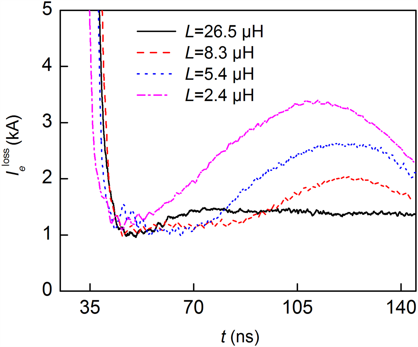
Fig. 11. Electron current loss for the helical-supported MITL in the self-limited case in Figure 10.

Fig. 12. Snapshots of electrons in the MITLs with different inductances in the YZ plane at 100 ns. The MITLs are operated in the self-limited case. The inductance of helical inductors in (a) and (b) are 26.5 and 2.4 µH, respectively.
It is clear that a smaller inductance causes a much higher magnetic field in the y direction, which is shown in the red region of Figure 13b. This field is much higher than the azimuthal magnetic field near the helical spring, which generates an electron flow vortex near the spring, shown in Figure 13a.

Fig. 13. Snapshots of (a) electrons and (b) the magnitudes of magnetic fields in the MITLs in Figure 12b in the XY plane at 100 ns.
Effects of structural parameters of the helical inductor on electron current loss of MITL
To investigate the effects of structural parameters of the helical spring on electron current loss, simulations of helical-supported MITLs with different springs were conducted. The inductance was fixed at 26.5 µH, as is the case for the inductor in Figure 4. For the helical spring of the MITL in simulations of Figure 14, R is set as 5 cm, to obtain a fixed inductance at 26.5 µH when a ranges from 12 to 36 cm, a/W varies from 4.8 to 9.6 mm according to the equation of inductance in “Simulation setup”. Results show that the electron current loss caused by the helical spring changes slightly with the length and the number of wings of the spring when the inductance of the spring is fixed. In Figure 15, a/W is set as 4.8 mm, when R varies from 20 to 60 mm, a varies from 10 to 30 cm to obtain a fixed inductance. Results reveal that a larger helical spring radius causes a higher electron loss in the MITL. The difference between the electron current loss of the larger-radius spring and that of the smaller-radius spring may be caused by the non-uniform distribution of the magnetic field. Therefore, a trade-off between a large electron current loss caused by a large-radius helical spring and the difficulty of support for a small-radius helical spring is required.

Fig. 14. Electron current loss versus voltage for MITLs in the self-limited case. The lengths of the helical spring are 12, 24, and 36 cm. The interval between the wings of the helical inductor varies from 4.8 to 9.6 mm.

Fig. 15. Electron current loss versus voltage for MITLs of geometry 3 in the self-limited case. The radius of the helical inductor varies from 20 to 60 mm.
As Figure 16 shows, the magnetic field near the outer cylinder is not disturbed in the MITL with the 3 cm-radius inductor, in contrast with the field of the MITL with the 5 cm-radius inductor, in Figure 5a. The results in Figure 17 show that the magnetic field before the inductor is uniform and it is beyond the critical magnetic field (B crit = 0.097 T). However, the magnetic field at the center of the inductor becomes non-uniform and exits abrupt changes from 60° to 120° along the angular path. After the inductor, the magnetic field fluctuations decrease, the average value of the intensity of the magnetic field after the inductor is about 91.5% of that before the inductor in Figure 17a and 93.2% of that in Figure 17b. The magnetic field near the helical spring of the MITL with the 3 cm-radius inductor is always higher than 0.096 T, which leads to a lower electron current loss.

Fig. 16. Magnetic fields of MITLs at the center of the inductor in the (a) YZ plane and (b) XY plane at 100 ns. The MITL is operated in the self-limited case. V = 0.74 MV.
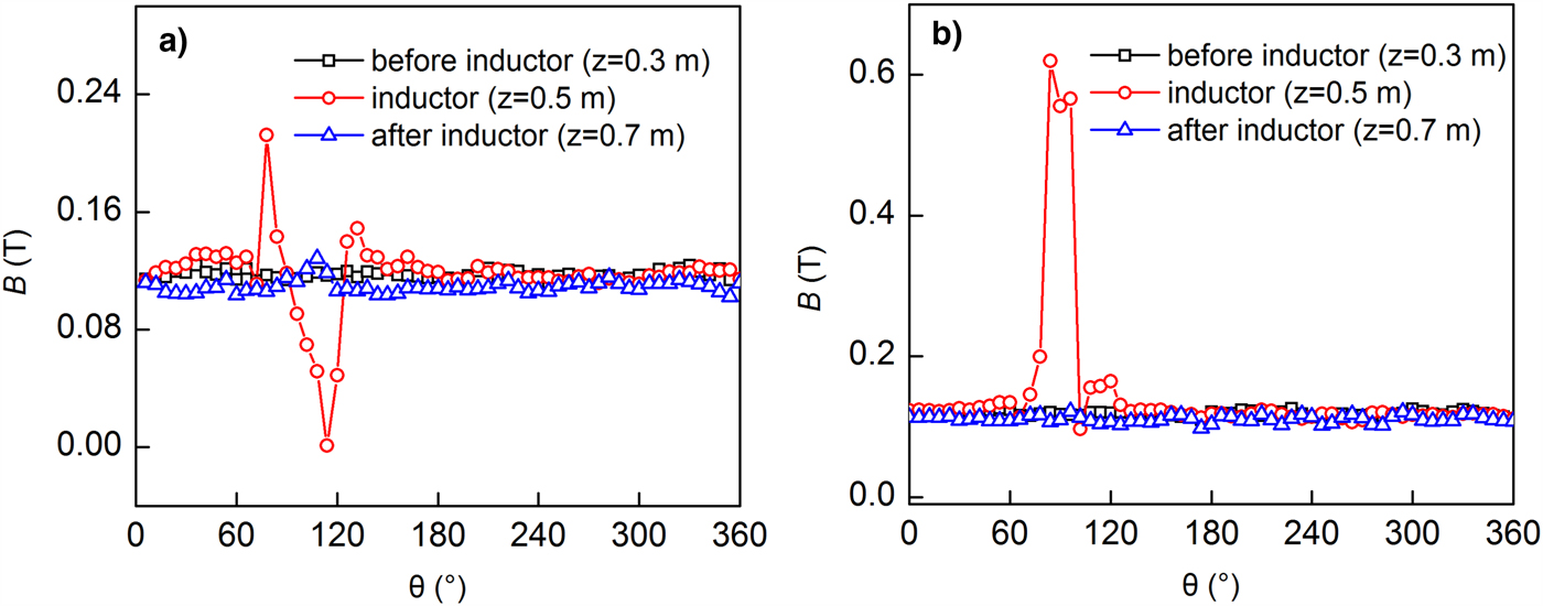
Fig. 17. Magnetic fields of MITLs with (a) 5 cm-radius and (b) 3 cm-radius inductor at 100 ns. The MITL is operated in the self-limited case.
As the helical support impacts the local magnetic field, when pulsed power propagates in the MITL, it is clear that the support will disturb electron flow and the working property of the load. Figure 18a shows current loss with distance from the helical support to the load, from 30 to 60 cm. The helical inductor is the same as that in Figure 4. As the distance from the support to the load increases, a smaller electron current is lost to the anode wall of the MITL. In the self-limited case of magnetic insulation for the MITL, a large distance between the support and the load means that the loss front is far from the helical support. Therefore, the electron flow of the MITL near the support is influenced only slightly. The snapshot of electrons in Figure 18b shows that the electron flow in the MITL is interrupted, becoming non-uniform again after the helical support. However, electron flow becomes uniform when the distance is larger than 40 cm.

Fig. 18. Electron current loss versus voltage for MITLs in the self-limited case, with different distances from the helical support to the load in (a) and snapshots of electrons in MITL when D SL is 70 cm in (b). The helical spring is the same as that in Figure 4.
As Figure 19a shows, the ratio of electron current loss to self-limited current,  $I_{\rm e}^{{\rm Loss}} /I_{\rm a}^{{\rm SL}} $, is as high as 3.22% when D SL = 30 cm at 5 MV, and is about 2.78% when D SL = 30 cm at 5 MV. To make
  $I_{\rm e}^{{\rm Loss}} /I_{\rm a}^{{\rm SL}} $ in the MITL less than 3% when the voltage varies from 0.5 to 5 MV, the distance from the spring to the load exceeding 0.4 m is an appropriate option. In Figure 19b, the ratio of electron current loss to self-limited current
  $I_{\rm e}^{{\rm Loss}} /I_{\rm a}^{{\rm SL}} $ for MITLs with springs of various radii changes from 1 to 2.6%. The inductance and structure of the inductor are the same as those in Figure 4. When the inductance of the helical inductor is 26.5 µH, the ratio of shunt current to total current is about 3%, which is higher than
  $I_{\rm e}^{{\rm Loss}} /I_{\rm a}^{{\rm SL}} $ at low voltage. If the inductance is sufficiently high, the electron current loss and inductor current are negligible when compared with the total current.

Fig. 19. Plots of  $I_{\rm e}^{{\rm Loss}} /I_{\rm a}^{{\rm SL}} $ as functions of operating voltage of the MITL with varied (a) distance from support to the load and (b) radius of helical spring. The inductance of the helical spring is 26.5 µH.
The self-limited impedance of the MITL is defined as  $Z_{\rm S} = V/I_{\rm a}^{{\rm SL}} $, which of the MITL with 26.5 µH inductor is compared with the theoretical model (Ottinger and Schumer, Reference Ottinger and Schumer2006) in Figure 20.
  $I_{\rm a}^{{\rm SL}} $ for the theoretical model can be calculated though:
 $$I_{\rm a}^{{\rm SL}} (V) = \displaystyle{V \over {Z_0f_{{\rm SL}}(V)}}\left[ {\displaystyle{{1 + \lpar {((g(V)mc^2)/2eV)-1} \rpar f_{{\rm SL}}(V)} \over {1-f_{{\rm SL}}(V)}}} \right]^{1/2},$$
 $$f_{{\rm SL}}(V) = {\eta} (V)f_{{\rm MC}}(V),$$
 $$ f_{\rm MC}(V) = \displaystyle{((g(V)mc^2/8eV)-1) + \lsqb ((g(V)mc^2/8eV)-1)^2 + ((g(V)mc^2/2eV)-1) \rsqb ^{1/2} \over ((g(V)mc^2/2eV)-1),}$$
where V and Z 0 are the operating voltage and vacuum impedance of the MITL, respectively. e, m, and c are the electron charge, electron mass, and the speed of light, respectively. g(V) = 0.99565 − 0.05332V + 0.0037V 2, η(V) = 0.82 + 0.0086V. The self-limited impedance of the MITL near the inductive helical support is  $Z_{\sup} = {\kern 1pt} V/I_{a\sup} ^{{\rm SL}} $. Results in Figure 20 reveal that Z sup/Z 0 of the MITL with a 6 cm-radius spring is about 0.97 times of the theoretical value, while Z sup/Z 0 of the MITL with a 2 cm-radius spring is about 0.985 times of Z S/Z 0.

Fig. 20. Self-limited impedance as a function of voltage for MITLs with varied-radius springs. The inductance of the helical spring is 26.5 µH.
Conclusion
In this paper, the current loss mechanism for an MITL supported with a helical inductor is discussed, and the effects of structural parameters of the inductor on electron flow were investigated using 3D PIC simulations. Results reveal that the current loss consists of the shunt current from the inductor and the electron current lost to the anode. The electron current loss reaches its maximum value when the helical-supported MITL is self-limited. The weakened azimuthal magnetic field near the helical spring prevents full magnetic insulation of the electron flow, and the flow is lost to the anode. The magnetic field produced by a small-inductance helical spring perturbs the electron flow and promotes electron current loss. An empirical expression for the ratio of electron current loss to anode current  $(I_{\rm e}^{{\rm Loss}} /I_{\rm a})$ as a function of the ratio of anode current to self-limited current
  $(I_{\rm a}/I_{\rm a}^{{\rm SL}} )$ is obtained. To ensure
  $I_{\rm e}^{{\rm Loss}} /I_{\rm a}$ is less than 0.5%,
  $I_{\rm a}/I_{\rm a}^{{\rm SL}} $ should be no less than 1.3.
Effects of helical inductors with different structures on electron flow were investigated when the inductance is fixed. The simulations are run using various voltage amplitudes. The radius of the helical spring is the key structural parameter which influences electron flow. To regain uniformity of the disturbed electron flow after the support and to achieve a  $I_{\rm e}^{{\rm Loss}} /I_{\rm a}^{{\rm SL}} $ less than 3%, the distance from the spring to the load should exceed 0.4 m.
  $I_{\rm e}^{{\rm Loss}} /I_{\rm a}$ varies from about 1 to 2.6% for the MITL with the 26.5 µH inductor, which indicates that the current loss of the inductive helical-supported MITL is negligible, when the inductance of the support is sufficiently high. This work addresses several important challenges associated with power flow in the inductive helical-supported MITL, and provides a simple solution to estimating the electron current loss caused by the inductive helical support.
Acknowledgments
This work is supported by the National Natural Science Foundation of China (No. U1530133).


