


1. Introduction
Construction of a superconducting fragment separator (Super-FRS) (Geissel et al., Reference Geissel, Weick, Münzenberg, Chichkine, Yavor, Aumann, Behr, Böhmer, Brünle, Burkahrd, Benlliure, Cortina-Gil, Chulkov, Dael, Ducret, Emling, Franczak, Friese, Gastineau, Gerl, Gernhäuser, Hellström, Johnson, Kojouharova, Kulessa, Kindler, Kurz, Lommel, Mittig, Moritz, Mühle, Nolen, Nyman, Rousell-Chomaz, Scheindenberger, Schmidt, Schrieder, Sherrill, Simon, Sümmerer, Tahir, Vysotsky, Wollnik and Zeller2003) at the future facility for antiprotons and ion research (FAIR) (Henning, Reference Henning2004) is one of the most important parts of this international project that will be used for production and separation of exotic radioactive isotopes. The production target is a central part of the fragment separator system, which should survive during these experiments carried out at a repetition rate of 1 Hz, over an extended period of time. However, due to the high beam intensity that will be available at the FAIR, designing a viable target that fulfills the above requirements is a difficult problem and is addressed this article.
It is expected that this new facility will deliver high quality heavy ion beams including uranium with very high intensities of about 5 × 10¹¹ particles/spill. A wide range of particle energies (400 MeV/u − 2.7 GeV/u) will be available while the beam could be focused to a spot of 1 mm radius. Both fast and slow extraction options will be available for the beam. In the former case, the bunch length will be on the order of 50–100 ns, while in the latter case, one will have a quasi-uniform beam power. Availability of such high intensity beams will also enable scientists to perform experiments in other fields of research including high-energy-density (HED) physics (Tahir et al., Reference Tahir, Hoffmann, Spiller and Bock1999, Reference Tahir, Hoffmann, Kozyreva, Shutov, Maruhn, Neuner, Tauschwitz, Spiller and Bock2000a, Reference Tahir, Hoffmann, Kozyreva, Tauschwitz, Shutov, Maruhn, Spiller, Nuener, Jacoby, Roth, Bock, Juranek and Redmer2000b, Reference Tahir, Kozyreva, Hoffmann and Shutov2001a, Reference Tahir, Hoffmann, Kozyreva, Tauschwitz, Shutov, Maruhn, Spiller, Nuener, Jacoby, Roth, Bock, Juranek and Redmer2001b, Reference Tahir, Winkler, Kojouharova, Rousell-Chomaz, Chichkine, Geissel, Hoffmann, Kindler, Landre-Pellemoine, Lommel, Mittig, Münzenberg, Shutov, Weick and Yavor2003a, 2005a, Reference Tahir, Adonin, Deutsch, Fortov, Grandjouan, Geil, Gryaznov, Hoffmann, Kulish, Lomonosov, Mintsev, Ni, Nikolaev, Piriz, Shilkin, Spiller, Shutov, Temporal, Ternovoi, Udrea and Varentsov2005b, Reference Tahir, Spiller, Udrea, Cortazar, Deutsch, Fortov, Gryaznov, Hoffmann, Lomonosov, Ni, Piriz, Shutov, Temporal and Varentsov2006, 2007a, 2007b; Piriz et al., Reference Piriz, Portugues, Tahir and Hoffmann2002, Reference Piriz, Tahir, Hoffmann and Temporal2003, Reference Piriz, Temporal, Lopez Cela, Tahir and Hoffmann2005, Reference Piriz, Lopez Cela, Serena Moreno, Tahir and Hoffmann2006, 2007a, 2007b; Temporal et al., Reference Temporal, Piriz, Grandjouan, Tahir and Hoffmann2003, Reference Temporal, Lopez-Cela, Piriz, Grandjouan, Tahir and Hoffmann2005; Lopez Cela et al., Reference Lopez Cela, Piriz, Serena Moreno and Tahir2006; Hoffmann et al., Reference Hoffmann, Blazevic, Ni, Rosmej, Roth, Tahir, Tauschwitz, Udrea, Varentsov, Weyrich and Maron2005). Another huge accelerator facility that is being built in Europe is the large hadron collider (LHC) at CERN. Recently, theoretical studies were carried out to investigate some of the safety issues related to this impressive machine (Tahir et al., Reference Tahir, Kain, Schmidt, Shutov, Lomonosov, Gryaznov, Piriz, Temporal, Hoffmann and Fortov2005d). An additional very interesting outcome of this work was that the LHC can be used to study HED physics (Tahir et al., Reference Tahir, Goddard, Kain, Schmidt, Shutov, Lomonosov, Piriz, Temporal, Hoffmann and Fortov2005e). Moreover, it has been shown that the 450 GeV/c proton beam delivered by the super proton synchrotron (SPS) at CERN, which will be used as injector to the LHC, also has enough energy to induce HED states in matter (Tahir et al., 2007c).
Previous theoretical investigations have shown that (Tahir et al., Reference Tahir, Juranek, Shutov, Redmer, Piriz, Temporal, Varentsov, Udrea, Hoffmann, Deutsch, Lomonosov and Fortov2003b, 2005c) due to huge instantaneous power deposition by fast extracted beams (up to 100 GW in case of full intensity of a high-Z beam) at FAIR, a solid Super-FRS production target will always be destroyed in a single experiment. It is therefore necessary to develop an alternate target concept, for example, a liquid jet metal target (Nolen et al., 2003) for the full intensity of the uranium beam. Detailed three-dimensional (3D) numerical simulations of interaction of a liquid jet lithium target with the uranium beam have recently been carried out and reported elsewhere (Tahir et al., 2007d). These simulations have been done using a 3D computer code, PIC3D (Fortov et al., Reference Fortov, Kim, Lomonosov, Matveichev and Ostrik2006). These results have provided very useful information that will allow one to develop a viable liquid metal target for the Super-FRS.
It has also been shown (Tahir et al., Reference Tahir, Deutsch, Fortov, Gryaznov, Hoffmann, Kulish, Lomonosov, Mintsev, Ni, Nikolaev, Piriz, Shilkin, Spiller, Shutov, Temporal, Ternovoi, Udrea and Varentsov2005c) that for moderate beam intensities, the specific power deposition can be reduced to an acceptable level by increasing the area of the focal spot. In practice, however, it is not possible to increase the focal spot size arbitrarily because of the resolution and transmission issues of the secondary isotopes. It is to be noted that the resolving power of the fragment separator is inversely proportional to the dimensions of the focal spot in horizontal direction (x-direction). Transmission of the radioactive nuclides through the fragment separator, on the other hand, depends only on the spot size in y-direction. It is therefore possible to use an elliptic focal spot with appropriate dimensions that will fulfill the necessary conditions for good resolution and reasonable transmission while at the same time, it will have large enough area to minimize specific energy deposition. Another very important problem in the Super-FRS is the removal of heat from the target continuously and efficiently. Otherwise accumulation of heat due to successive experimental shots will eventually destroy the targe. This problem has been studied in detail (Tahir et al., Reference Tahir, Deutsch, Fortov, Gryaznov, Hoffmann, Kulish, Lomonosov, Mintsev, Ni, Nikolaev, Piriz, Shilkin, Spiller, Shutov, Temporal, Ternovoi, Udrea and Varentsov2005c) for a solid graphite target using numerical simulations. It has been shown that if one employs a wheel shaped solid target that is rotated at a suitable speed so that the interval between successive times a specific part of the target is irradiated, is substantially increased, that region will cool due to thermal conduction and the temperature increase can be controlled.
In the previous work, however, we did not study the problem of thermal stresses induced by the beam in the target material, which is an important issue for the target stability and survival. This problem is discussed in the present paper where we report simulations that have been done using a 3D computer code that includes a model to treat the elastic-plastic behavior of the material. This work has shown that the solid target will survive the thermal stress for up to an intensity of 1011 uranium ions/spill. For higher intensities, the target will be destroyed due to the thermal stress.
In Section 2, we discuss the specific problems involved in designing a solid target for the Super-FRS while the beam and target parameters considered in this study are noted in Section 3. The 3D computer code, PIC3D, used to do target simulations, is described in Section 4. Numerical simulation results are reported in Section 5, and the conclusions drawn from this work are presented in Section 6.
2. PROBLEM DEFINITION
Survival of a solid production target in Super-FRS experiments is dependent on two important parameters. First, the temperature, which should remain safely below the melting or sublimation temperature of the material. Second, the thermal stresses induced by the beam should always be less than the tensile strength of the material so that the stress waves do not inflict permanent damage to the material before being damped out. This means that the target material should always remain in elastic regime during the experiments.
Solid graphite is a very attractive material as it has a very high sublimation temperature of 3925 K and has already been tested and used at other facilities for construction of production targets (Heidenreich, Reference Heidenreich2002) for continuous beams. However, such target concept has never been employed in practice for very high intensity fast extracted beams like those at the Super-FRS. Due to the technical challenges involved in construction and operation of a liquid metal jet target, it is desirable to use a solid graphite target during the early and intermediate stages of the FAIR project when the full beam intensity will not be available. Since Super-FRS experiments will be carried out at a repetition rate of 1 Hz, it is necessary to remove heat from the target efficiently to avoid accumulation of the deposited energy that may eventually lead to target destruction after multiple irradiations. It has been proposed to use a wheel shaped graphite target that is rotated at a suitable frequency so that the same part of the target is not exposed to the beam consecutively and by the time this part is again irradiated by the projectile particles, it is substantially cooled due to thermal conduction. Detailed numerical simulations of such a scheme have been reported previously (Tahir et al., Reference Tahir, Deutsch, Fortov, Gryaznov, Hoffmann, Kulish, Lomonosov, Mintsev, Ni, Nikolaev, Piriz, Shilkin, Spiller, Shutov, Temporal, Ternovoi, Udrea and Varentsov2005c), which have shown that this concept can be employed successfully in case of a solid graphite Super-FRS target.
In a fast extraction scheme, the beam energy is instantaneously deposited in the target as internal energy that appears as thermal pressure. Since the energy distribution is Gaussian, the pressure gradient leads to hydrodynamic motion and shear that gives rise to stress in the material. The magnitude of the induced stress depends on the pressure gradient. It is important that the level of induced stress remains below the yield strength of the material so that the material remains in elastic regime and the target is restored to its original state after every time it is irradiated by the beam. In the present study, we report calculations done to investigate the above problem using a 3D computer code PIC3D (Fortov et al., Reference Fortov, Kim, Lomonosov, Matveichev and Ostrik2006) that includes an elastic-plastic model as explained in Section 4.
It is also to be noted that in August 2007, experiments were performed at the GSI plasma physics high temperature experimental area (HHT) to study some of the material properties of graphite using the uranium beam that is available at the existing heavy ion synchrotron, SIS18. Numerical simulations of these experiments were also carried out and reported elsewhere (Tahir et al., 2007e).
3. BEAM AND TARGET PARAMETERS
In this section, we provide beam and target parameters used in the simulations carried out employing the code PIC3D. We consider a uranium beam with a particle energy of 1 GeV/u having a bunch length, τ = 50 ns. Several cases with different values of beam intensity, N, and different focal spot geometries, and dimensions, have been used. The transverse intensity distribution in the focal spot is assumed to be Gaussian. The geometry and the dimensions of the focal spot are chosen within the limits of achieving a reasonable level of resolution and transmission of the secondary isotopes. That means in case of an elliptic focal spot using σX ≤ 2 mm and σY ≤ 12 mm (Tahir et al., Reference Tahir, Deutsch, Fortov, Gryaznov, Hoffmann, Kulish, Lomonosov, Mintsev, Ni, Nikolaev, Piriz, Shilkin, Spiller, Shutov, Temporal, Ternovoi, Udrea and Varentsov2005c). In order to study the effect of the focal spot geometry on the target stability, we have also considered a circular focal spot with an area equal to the elliptic focal spot for one beam intensity. The target is a solid graphite cylindrical disc with a thickness of 3 g/cm2 and a radius of 5 cm. The beam is incident on one face of the target and since the range of 1 GeV/u uranium particles is much larger than the target length, the projectile particles loose a fraction (30% in this case) of their energy in the target material and emerge from the opposite face of the cylinder with reduced energy. As the Bragg peak lies outside the target, energy deposition is fairly uniform along the particle trajectory and the problem becomes (2D). We therefore use 2D version of the 3D code and perform the simulations along the cylinder cross section in the middle of the target (half length of the cylinder).
3.1. Case 1
N = 1010 ions/spill.
3.1.1. Case 1a
Using an elliptic focal spot with σX = 1 mm and σY = 2 mm.
3.1.2. Case 1b
Using a circular focal spot with σ = 1.3 mm.
3.1.3. Case 1c
Using an elliptic focal spot with σX = 0.41 mm and σY = 4.1 mm. The focal spot area in this case is the same as in case Ib.
3.2. Case 2
N = 5.0 × 10¹⁰ ions/spill assuming an elliptic focal spot with σX = 1.2 mm and σY = 12 mm.
3.3. Case 3
N = 1011 ions/spill assuming an elliptic focal spot with σX = 2 mm and σY = 12 mm.
4. THREE-DIMENSIONAL COMPUTER CODE
The PIC3D computer code that has been employed to do these simulations is based on a finite-size particle-in-cell (PIC) method, which uses a two-stage Lagrange-Eulerian approach. In the first Eulerian stage, an implicit conditionally–stable (even at zero artificial viscosity) finite–difference scheme is considered. The convective transport of matter is simulated in the Lagrangian step by movement of finite–size particles, which carry all the flow parameters through the Eulerian cell boundaries. As a result, this method leads to obtaining monotonic parameters profiles and tracking of body interfaces in a self consistent manner by the particles. Artificial viscosity is used to smooth pressure profiles at shock front. For metal targets, a multi-phase equation-of-state (Lomonosov, Reference Lomonosov2007) is used to model different phases of matter in beam-target interaction studies.
To simulate elastic–plastic properties of solids, the ideal plasticity model is used. That means Hook's law complemented with R. von Mises yield condition to describe the elastic limit. To describe material behavior in elastic regime, Prandtl-Reuss equation is used:
where s ij is the deviatoric part of stress tensor, e ij = 1/2(∂v i/∂xi + ∂v j/∂xi) is the components of strain tensor ![]() , δij is the Kroneker delta, and G is the shear modulus.
, δij is the Kroneker delta, and G is the shear modulus.
To describe plastic regime of material deformation, von Mises yield criterion with Wilkins normalizing procedure is considered:

where J = ∑i=13 ∑j=13σij2, where Y 0 is the yield strength. It is convenient to use parameter M = J(3/2Y02), which displays the current flow regime. Material is in elastic state if M < 1, and when M + 1, plastification occurs.
The heavy ion beam energy deposition is handled by a particle tracking scheme. For the equation of state of carbon, we use SESAME equation of state data (Kerley, Reference Kerley2001). In the simulations, we use G = 12 GPa and Y = 65 MPa (SGL Carbon, private communication).
5. NUMERICAL SIMULATION RESULTS
In this section, we present numerical simulation results for the cases noted in Section 3. Since the problem is 2D, we have done simulations using 2D version of the 3D code in the cross sectional plane of the cylinder at the center of the target (middle of the length). The results are given below.
5.1. Case 1
In these calculations we assume N = 1010 uranium ions per spill.
5.1.1. Case 1a
An elliptic focal spot with σx = 1 mm and σy = 2 mm is considered. In Figures 1a and 1b, are plotted the target temperature and pressure, respectively, at t = 50 ns (at the end of the pulse) versus x and y coordinates. It is seen that a maximum temperature of about 510 K and a maximum pressure of 160 MPa is generated at the center of the Gaussian distribution. The elliptic nature of the focal spot and the gradients of temperature and pressure due to the Gaussian deposition distribution are also reflected in these profiles.

Fig. 1. (Color online) N = 1010 ions/bunch, τ = 50 ns, elliptic focal spot with Gaussian transverse intensity distribution, σx = 1.0 mm, σy = 2.0 mm (a) temperature versus x and y coordinates at t = 50 ns; (b) pressure versus x and y coordinates at t = 50 ns.
The pressure gradient leads to hydrodynamic motion spreading radially outward as is seen in Figures 2a–2f, which are plotted at different times after irradiation. Figure 2a is plotted at t = 50 ns that shows 2D pressure distribution immediately after the beam has delivered its total power. Figure 2b shows propagation of the pressure waves from the central high pressure region. It is seen that the pressure wave is more pronounced along the x-axis due to a higher initial pressure gradient in this direction. It is also seen that the pressure decreases as the wave spreads and negative pressure develops behind the wave. Further propagation of the wave is shown in Figure 2c which is plotted at t = 2 µs. Figure 2d shows that the wave has arrived at the target boundary at t = 10 µs.The wave is reflected at the boundary and Figure 2e shows the inward propagation of the reflected wave at t = 18 µs that arrives at the center at t = 22 µs, as shown in Figure 2f.

Fig. 2. (Color online) Cross sectional view of target pressure at different times; (a) t = 50 ns; (b) t = 1 µs; (c) t = 2 µs; (d) t = 10 µs; (e) t = 18µs; (f) t = 22 µs for the case presented in Fig. 1.
This hydrodynamic motion produces shear in the target that generates deviatoric stress in the material. The stress level should be kept to a minimum so that the von Mises criterion described in Section 4 is not violated, namely, the parameter, M is always less than one. In Figures 3a–3c we plot respectively, the xx, yy, and xy component of deviatoric part of the stress tensor while Figure 3d shows the value of the von Mises parameter at different times after irradiation. It is seen that for the above set of beam parameters, the target will survive as the material will remain in the elastic regime.

Fig. 3. (Color online) (a) xx-component of stress tensor; (b) yy-component of stress tensor; (c) xy-component of stress tensor, and (d) von Mises parameter versus x-axis at different times for the case presented in Figure 1.
5.1.2. Case 1b
It is also important to study the effect of focal spot geometry on target stability. For this purpose, we consider a circular focal spot with σ = 1.3 mm that is the minimum value for which the material will remain elastic. The temperature and pressure profiles at t = 50 ns for this case are plotted in Figures 4a and 4b, respectively. It is seen that one achieves a maximum temperature of about 540 K and a pressure of 180 GPa. Different components of the stress tensor and the von Mises parameter are presented in Figure 5. It is seen that despite the fact that the pressure in this case is higher than the previous one, the value of the von Mises parameter is the same in both cases. This is due to the fact that a circular focal spot generates less shear and hence less stress compared to an elliptic focal spot. To further illustrate this effect quantitatively, we also carried out simulations using a focal spot with a ratio of 10 between y and x dimensions while keeping the same area as in the present case so that the specific energy deposition is same in both cases. The results are described below.

Fig. 4. (Color online) N = 1010 ions/bunch, τ = 50 ns, circular focal spot with Gaussian transverse intensity distribution, σ = 1.3 mm; (a) temperature versus x and y coordinates at t = 50 ns; (b) pressure versus x and y coordinates at t = 50 ns.

Fig. 5. (Color online) (a) xx-component of stress tensor; (b) yy-component of stress tensor; (c) xy-component of stress tensor and (d) von Mises parameter at t = 1µs for the case presented in Figure 4.
5.1.3. Case 1c
In this case, we consider σx = 0.41 mm and σy = 4.1 mm so that the focal spot area is the same as in Case 1b. The temperature and pressure profiles at t = 50 ns are plotted in Figures 6a and 6b, respectively. It is seen that the same maximum values of temperature and pressure are achieved as in Figures, 4a and 4b, respectively. However, the respective profiles have different distributions due to the different shapes of the focal spot.

Fig. 6. (Color online) N = 1010 ions/bunch, τ = 50 ns, elliptic focal spot with Gaussian transverse intensity distribution, σx = 0.41 mm, σy = 4.1 mm (a) temperature versus x and y coordinates at t = 50 ns; (b) pressure versus x and y coordinates at t = 50 ns.
The xx, yy, and xy components of the stress tensor are presented in Figuers 7a–c, respectively while the von Mises parameter is shown in Figures 7d at t = 1 µs. It is seen that in this case, the parameter M approaches the critical value of one at the target center that means that the material in this region will be plastified. The reason for this big difference in the results of Cases 1b and 1c is as follows. The von Mises parameter depends on the shear, which is generated by the pressure gradients. These gradients are minimum for a perfectly circular focal spot and therefore a higher thermal pressure can be tolerated by the material, whereas an elliptic focal spot (for the same specific energy) produces higher gradients that translate into higher shear stresses. This is clearly seen from a comparison of Figures 5 and 7 where the different components of the stress tensor and the von Mises parameter for the two geometries of the focal spot are presented. It is therefore recommended that one should use a circular focal spot instead of an elliptic one provided one can fulfill the conditions of achieving good resolution and sufficient transmission. This is feasible for moderate beam intensities.

Fig. 7. (Color online) (a) xx-component of stress tensor; (b) yy-component of stress tensor; (c) xy-component of stress tensor, and (d) von Mises parameter at t = 1 µs for the case presented in Figure 6.
5.2. Case 2
This case considers a beam intensity of 5.0 × 10¹⁰ uranium ions/spill using an elliptic focal spot with σX = 1.2 mm and σY = 12 mm. Figures 8a and 8b show the temperature and the pressure profiles at the end of the pulse (t = 50 ns). It is seen that the maximum temperature of 450 K and a maximum pressure of 117 MPa is generated at the center of the Gaussian. Evolution of pressure in time is seen in Figures 9a–9f. Propagation of the pressure wave from the center toward the target boundary, reflection of the wave from the outer boundary, and then arrival of the reflected wave at the target axis is clearly seen. It is interesting to see the stark difference between the wave propagation in the present case and that in Case 1a where the ellipticity of the focal spot is two that behaves almost like a circular spot.

Fig. 8. (Color online) N = 5 × 10¹⁰ ions/bunch, τ = 50 ns, elliptic focal spot with Gaussian transverse intensity distribution, σx = 1.2 mm, σy = 12.0 mm (a) temperature versus x and y coordinates at t = 50 ns; (b) pressure versus x and y coordinates at t = 50 ns.

Fig. 9. (Color online) Cross sectional view of target pressure at different times; (a) t = 50 ns; (b) t = 1 µs; (c) t = 5 µs; (d) t = 10 µs; (e) t = 18 µs; (f) t = 22 µs for the case presented in Fig. 8.
The different components of the stress tensor and the Mises parameter achieved at t = 1 µs are plotted in Figures 10a–10d. It is seen that the von Mises parameter is about 0.7, which means that the target will survive this set of beam parameters. It is interesting to note that the same value of the von Mises parameter is achieve in case 1a for a significantly higher value of initial thermal pressure (160 MPa). This is because in case 1a, the ellipticity of the focal spot is two whereas in the present case it is 10 that leads to generation of much higher shear.

Fig. 10. (Color online) (a) xx-component of stress tensor; (b) yy-component of stress tensor; (c) xy-component of stress tensor, and (d) Mises criterion at t = 1 µs for the case presented in Figure 8.
5.3. Case 3
In this case, we consider a beam intensity of 1011 uranium ions/spill using an elliptic focal spot with σX = 2 mm and σY = 12 mm. The corresponding temperature and the pressure profiles are plotted in Figures 11a–11b, respectively, which show a maximum temperature of 475 K and a maximum pressure of 137 MPa. The evolution of the pressure is presented in Figures 12a–12f, respectively. The value of the von Mises parameter is 0.7. This again is due to the fact that in this case, the ellipticity of the focal spot is six, which is less than that in Case 2, and as a result the target survives with a higher initial thermal pressure.
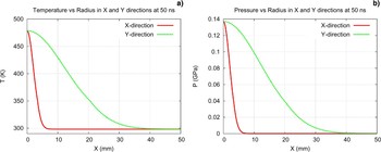
Fig. 11. (Color online) N = 1011 ions/bunch, τ = 50 ns, elliptic focal spot with Gaussian transverse intensity distribution, σx = 2.0 mm, σy = 12.0 mm (a) temperature versus x and y coordinates at t = 50 ns; (b) pressure versus x and y coordinates at t = 50 ns.

Fig. 12. (Color online) Cross sectional view of target pressure at different times; (a) t = 50 ns; (b) t = 1 µs; (c) t = 5 µs; (d) t = 10 µs; (e) t = 18 µs; (f) t = 22 µs for the case presented in Fig. 8.
6. CONCLUSIONS
The problem of beam induced thermal stresses in a solid graphite production target for the Super-FRS for a fast extraction scheme at the FAIR facility, has been thoroughly studied using a 3D computer code, PIC3D. A wide range of intensity, namely, 1010–1011 of 1 GeV/u uranium ions per spill has been considered. The bunch length is 50 ns while the transverse intensity distribution in the focal spot is assumed to be Gaussian. In radioactive beam generation experiments, resolution of the isotopes and transmission of the secondary beam through the fragment separator are very important problems. The resolving power of the fragment separator is inversely proportional to the x-dimensions of the focal spot and an acceptable value of σx = 2.0 mm. The transmission, on the other hand, depends on the y-dimensions of the focal spot and in case of the Super-FRS, one can have σy up to 12 mm. An elliptic focal spot can therefore be used that will fulfill the above conditions while at the same time it will lead to an acceptable level of energy deposition for up to N = 1011 uranium ions per spill so that the target is not destroyed either by sublimation or by thermal stresses. A solid target, however, will not work for higher beam intensities using the above focal spot parameters and it is necessary to develop an alternate target design like a liquid jet target.
It has also been found that a circular focal spot is more advantageous compared to an elliptic focal spot because the former generates minimum pressure gradients compared to the latter. As a consequence, the stress level generated in a target irradiated with a perfectly circular focal spot is significantly less than that produced by an elliptic focal spot for the same specific energy. In addition to that, this effect becomes more pronounced as the ellipticity of the focal spot increases. It is therefore recommended that for moderate beam intensities, one should use a circular focal spot as long as one can achieve a good isotope resolution and a reasonable level of transmission.
Acknowledgments
The authors would like to thank H. Geissel, A. Kelic, K. Suemmerer, H. Weick, and M. Winkler for many useful discussions. This work was financially supported by the BMBF, Germany and RFBR grant No.06-02-04011-NNIOa, Russia.


