


Introduction
Microstrip slot antennas are good radiators offering low profile, compact size, conformability, and low cost [Reference Yoshimura1–Reference Sze and Wong5]. Compared to microstrip patch antennas, microstrip slot antennas have wider impedance bandwidth, lower cross-polarization level, and bidirectional radiation, making them attractive for several applications such as radar communication, satellite communication, and global positioning system [Reference Garg, Bhartia, Bahl and Ittipiboon3]. In certain specialized applications such as wireless body area network, wireless personal area network, non-destructive evaluation etc., antennas with directional radiation pattern over a wide bandwidth are desired [Reference Klemm, Kovcs, Pedersen and Troster4]. Several techniques have been proposed for improving the bandwidth, gain, and directivity of microstrip antennas. The approaches for bandwidth enhancement are based on the modification of either the feed [Reference Sze and Wong5–Reference Sung8] or the radiating element [Reference Jan and Su9–Reference Lu and Zhu.11]. Loading partially reflective surfaces [Reference Feresidis and Vardaxoglou12] and dielectric superstrates [Reference Meagher and Sharma13, Reference Alkhatib and Drissi14] are proposed for increasing both the bandwidth and the gain of both patch and slot antennas. Dielectric substrates [Reference Jackson and Alexopoulos15, Reference Kaymaram and Shafai16], electromagnetic bandgap materials [Reference Lee, Yeo, Mittra and Park17, Reference Menudier, Chantalat, Thevenot, Monediere, Dumon and Jecko18], frequency selective surfaces [Reference Lee, Lee, Yeo, Mittra and Park19], and artificial magnetic surfaces [Reference Attia, Yousefi, Bait-Suwailam, Boybay and Ramahi.20] are also investigated to be used as superstrates for gain enhancement.
Even though fully reflecting elements such as conducting sheets are popularly used as reflectors for directivity (front-to-back ratio (FBR)) enhancement [Reference Klemm, Kovcs, Pedersen and Troster4, Reference Von Trentiny21, Reference Dash, Khan, Kanaujia and Antar22], the same with the slightly different design are also employed as superstrates [Reference Dutta, Guha, Kumar and Antar23–Reference Dash, Khan, Kanaujia and Nasimuddin26]. In [Reference Dutta, Guha, Kumar and Antar23, Reference Fakhte and Ghorbaninejad24], a conducting superstrate of side ~λ 0 is placed at ~λ 0/2 distance from the ground plane of the primary antenna to form a resonant cavity antenna. The cavity so formed introduces an additional resonance close to the primary resonance, to increase the impedance bandwidth, which also radiates with an enhanced gain due to the increased field strength of the cavity antenna [Reference Dutta, Guha, Kumar and Antar23].
In the present paper, an offset microstrip fed, rectangular slot antenna with a pair of conducting sheets is proposed for wideband, directional radiation in the 6–9 GHz band. This band is recommended by the European Electronic Communications Committee (ECC) for UWB communication [27]. ANSYS HFSS [28] is used for performing parametric analysis and design optimization, which later is verified with prototype fabrication and antenna characterization. This work is unique in the following aspects,
(i) The antenna uses the conducting superstrate as a parasitic element, unlike that in resonant cavity antennas [Reference Dutta, Guha, Kumar and Antar23, Reference Fakhte and Ghorbaninejad24].
(ii) Unlike broadband antenna designs that are optimized solely for the impedance bandwidth (reflection coefficient ≤−10 dB), the present design is optimized for the radiation bandwidth. The radiation bandwidth is defined as the band over which the reflection coefficient (|Γin|) ≤−10 dB, gain ≥5 dBi, cx-pol level ≤−10 dB, and FBR ≥10 dB. The above threshold levels are adopted so as to suit most of the communication applications.
Antenna principle
A basic slot antenna comprises a rectangular slot formed on a conducting ground plane that forms one side of a dielectric substrate. The slot resonates when its length is a half-wavelength or Ls ~ λg/2 at the operating frequency. Here λg, the guide wavelength is approximated as ~λ 0/ɛeff 0.5, where λ 0 is the free-space wavelength and ɛeff is the average dielectric constant between the substrate and the air medium [Reference Kumar, Piyush and Praveen Kumar7]. To enable wideband operation, the basic slot antenna is modified as follows. The slot width Ws is increased beyond the limit of narrow slots (Ws << Ls) for improving the impedance bandwidth [Reference Lu and Zhu.11, Reference Kraus and Marhefka29]. Next by offset-feeding the slot with a microstrip line, the impedance bandwidth is significantly enhanced through the merging of two radiating resonances of identical polarizations [Reference Behdad and Sarabandi6, Reference Kumar, Piyush and Praveen Kumar7]. Now, for achieving unidirectional radiation (FBR >> 1), the conventional technique of reflector loading with a conducting sheet of side >λ 0 [Reference Kraus and Marhefka29], located at ~λ 0/4 from the slot [Reference Yoshimura1, Reference Garg, Bhartia, Bahl and Ittipiboon3] may be employed. Even though the above design provides a wide band (>20% approximately)-directional antenna, it fails to provide a stable radiation performance throughout the impedance band. This is because, the slot radiation is distorted by the spurious radiation from the offset feed, especially at the higher frequencies of the impedance band. Thus, the useful radiation bandwidth (defined in the previous section) becomes much smaller than the impedance bandwidth. To correct this, a second conducting sheet can be used as a superstrate to enhance only the slot radiation throughout the band, thereby reducing the pattern distortion. Unlike in the resonant cavity antennas, here the superstrate will function as a parasitic element, similar to the director of a Yagi antenna, to control only the radiated fields of the primary antenna (driven element) in the given impedance band. A schematic diagram of the proposed antenna is shown in Fig. 1.

Fig. 1. Schematic diagram (side view) of the basic slot antenna loaded with superstrate and reflector sheets.
Antenna geometry
Figure 2 depicts the geometry of the proposed antenna where a rectangular slot of length Ls and aspect ratio Ws/Ls is etched on the ground plane backed substrate (FR-4) of size L × W. A standard 50 Ω microstrip line of length Lf feeds the slot at an offset d from the center of the slot on the other side of the substrate. Also shown in the figure, loaded a pair of conducting sheets, one as a superstrate of size L_sup × W_sup and the other as a reflector of size L_ref × W_ref, at heights h_sup and h_ref, respectively, from the microstrip feed. In the HFSS model of the antenna, FR-4 slab (ɛ r = 4.4 and loss tangent = 0.02) with a thickness of 1.6 mm is used for the substrate and PEC sheets for metallic bodies.

Fig. 2. Geometry of the proposed offset-fed slot antenna with dual-sheet loading (a) 3-D view (b) side view (yz-plane) (c) top view (xy-plane).
Parametric analysis
The basic slot antenna
To start with, a basic offset-fed rectangular slot antenna of slot length L s = 13 mm which is equal to λ g/2 at 7.5 GHz, the center frequency of 6–9 GHz, is analyzed. Here λ g is the guide wavelength estimated as discussed in the section ‘Antenna principle’. This rectangular slot is printed on the ground plane backed substrate of side L (or W) = 50 mm. In the HFSS parametric model, the slot width Ws is varied so that the aspect ratio varies as 0.25 ≤ Ws/Ls ≤ 1. In each case, the microstrip length parameter Lf and offset parameter d (Fig. 2(c)) are optimized to achieve maximum bandwidth. For any aspect ratio, the offset parameter d for the maximum bandwidth is found nearly constant at d ~0.35Ls = 4.55 mm. In Table 1, the optimization results of the aspect ratio are depicted. The table shows that Ws/Ls = 0.72 gives the maximum impedance bandwidth from 5.92 to 8.56 GHz (36%) with peak in-band gain >5.65 dBi and peak in-band cx-polar level <−17 dB in both the principal planes. If the −9.42 dB impedance band is considered, then the upper cut-off frequency of the band extends to 10.14 GHz. To assess the usefulness of the above impedance band for radiation, the radiation bandwidth is defined as the band that gives the reflection coefficient ≤−10 dB, peak gain ≥5 dBi, and peak cx-polar level ≤−10 dB. The basic slot antenna being bidirectional, the FBR is unity and is excluded from the above set of criteria. Figure 3 illustrates the radiation bandwidth which is only 18.40% from flow = 5.92 GHz to fhigh = 7.12 GHz.

Fig. 3. Demonstration of the radiation bandwidth (shaded region) of the basic slot antenna.
Table 1. Performance characteristics of the basic offset-fed slot antenna (Ls = 13 mm, L = W = 50 mm, d = 4.55 mm) for various aspect ratios (Ws/Ls).

Superstrate/reflector optimization
For the rectangular slot antenna, the radiation occurs mainly from the two opposing edges, each of length W s, separated by distance L s [Reference Balanis2]. Hence the shape of the superstrate and the reflector for controlling the radiated fields can also be of rectangular shape, to result in a smaller overall antenna size compared to those with square-shaped superstrate or reflector. Initially, the effect of the superstrate sheet of size L_sup × W_sup placed at a height h_sup from the slot is investigated. A parametric study is performed in HFSS by varying one of the superstrate parameters at a time while keeping the other two constant. Resulting radiation characteristics are summarized in Tables 2–4. Tables show that the optimum superstrate parameters are W_sup = 12 mm (~λ 0/3), L_sup = 45 mm (~1λ 0) and h_sup = 6.4 mm (~λ 0/6) from the slot in Fig. 2(b), giving an impedance bandwidth from 5.84 to 9.76 GHz, which is nearly identical to that of the basic slot antenna. Although the impedance matching near the upper band edge is improved slightly, the superstrate functions more like a parasitic element than a resonant cavity element as in [Reference Dutta, Guha, Kumar and Antar23, Reference Fakhte and Ghorbaninejad24]. Now the radiation bandwidth (without including FBR ≥10 dB criterion) is calculated as from 5.84 to 8.84 GHz or 40.87% which is ~2.5 times higher than that of the basic slot antenna (18.4%).
Table 2. Performance characteristics of superstrate loaded slot antenna for various width (W_sup) of the superstrate (L_sup = 45 mm, h_sup = 8 mm).

Table 3. Performance characteristics of superstrate loaded slot antenna for various length (L_sup) of the superstrate (W_sup = 12 mm, h_sup = 8 mm).

Table 4. Performance characteristics of superstrate loaded slot antenna for various height (h_sup) of the superstrate (L_sup = 12 mm, W_sup = 45 mm).

Next, a reflector sheet of size W_ref × L_ref is loaded below the slot (on the feed side) at a distance h_ref as shown in Fig. 2, for improving the FBR of the antenna. From the parametric study, it is found that the optimum reflector parameters are W_ref = 80 mm (2λ 0), L_ref = 40 mm (λ 0), and h_ref = 9.6 mm from the slot (~λ 0/4), giving peak FBR of 29.17 dB and peak boresight gain of 9.19 dBi in the impedance band of 6.08–10.37 GHz (52.17%). However, the radiation bandwidth for the reflector loaded slot antenna is found only 6.08–7.25 GHz or 17.55%, approximately identical to that of the basic slot antenna (18.4%).
From the optimum designs of the superstrate and the reflector sheets, one can observe that for either of the parasitic elements, the sides that are parallel to the slot length (Ls) are of the same length ~1 λ 0. On the other hand, the sides that are parallel to the slot width (Ws) is ~λ 0/3 for the superstrate, and ~2 λ 0 for the reflector. The above dependence is obviously attributed to the fact that only two out of the four edges of the slot contribute to prominent radiation, and the parasitic sheet sides that are parallel to those edges become critical in deciding the role of each sheet.
Combined effect of the superstrate and the reflector
Now the slot antenna is loaded with individually optimized superstrate and reflector sheets. The reflection coefficient of the resulting antenna is compared with that of the basic slot antenna, the same loaded with the superstrate and the reflector, in Fig. 4. The combined effect of superstrate and reflector is further demonstrated in the co-polar radiation patterns shown in Fig. 5 at three different frequencies in the band, i.e., 6.57, 7.25, and 8.2 GHz. It is evident that the dual conducting sheet loading has improved the boresight gain and the FBR of the basic slot antenna. Comparison of the co-polar and the cross-polar radiation patterns reveal that the antenna is linearly polarized throughout the band. The polarization of the antenna can further be confirmed from the simulated surface current density (A/m) distribution on the superstrate shown in Fig. 6. The y-directed current density plots indicate y-polarized radiation throughout the band. A radiation bandwidth from flow = 6.08 GHz to fhigh = 9.01 GHz (38.83%) can be read from Fig. 7, which almost matches with the design bandwidth of 6–9 GHz.
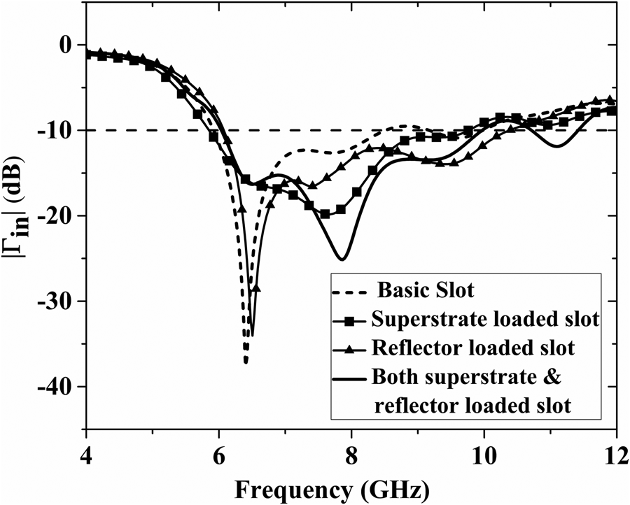
Fig. 4. Effect of conducting sheet (superstrate, reflector and both) loading on the reflection coefficient (|Γin|) of the basic slot antenna.

Fig. 5. Simulated radiation patterns (XZ and YZ-planes) of the basic slot antenna and the conducting sheet loaded slot antenna.

Fig. 6. Surface current density distribution on the superstrate at (a) 6.57 GHz (b) 7.25 GHz (c) 8.2 GHz.

Fig. 7. Demonstration of the radiation bandwidth (shaded region) for the dual-sheet loaded slot antenna.
Experimental results
To validate the simulation results, prototypes of the optimized basic slot antenna and the dual-sheet loaded slot antenna are fabricated, the photograph of which is shown in Fig. 8. The sheets are separated from the substrate by using Teflon spacers and glue. Keysight Technologies N-9928A Vector Network Analyzer and standard anechoic chamber are used for antenna measurements. Figure 9 shows both the measured and simulated reflection coefficients and gain of the antenna as a function of frequency. Measured impedance bandwidth is 6.05–10.51 GHz or 53.86% about the center frequency while the simulated bandwidth is 6.02–9.97 GHz or 49.41%. Peak in-band gains are 11.76 and 10.11 dBi, respectively, in simulation and measurement. Measured co-polar radiation patterns of the antenna at three different frequencies in the band are presented along with simulated patterns in Fig. 10. Measured radiation patterns are in decent agreement with simulated patterns. Attempts to measure the cross-polar pattern over the wide antenna bandwidth were unsuccessful, due to the high sensitivity of the weak cross-polar radiation to measurement errors. Thus, the cross-polar level is not considered as a criterion in deciding the measured radiation bandwidth. Table 5 presents a comparison between the simulated and measured results. Measured radiation bandwidth is 6.05–8.22 GHz or 30.41% with a peak gain of 10.11 dBi and peak FBR of 26.85 dB. Mismatches between the measured and the simulated results are attributed to the errors in the antenna fabrication and the measurement.

Fig. 8. Photograph of the fabricated dual-sheet loaded slot antenna prototype.

Fig. 9. Measured versus simulated reflection coefficients and gain of the dual-sheet loaded slot antenna (Fig. 8).

Fig. 10. Measured radiation patterns (XZ- and YZ-planes) of the basic slot antenna and the dual-sheet loaded slot antenna
Table 5. Measured performance characteristics of the dual-sheet loaded slot antenna with (L = W = 50 mm, Ls = 13 mm, Ws = 9.36 mm, L_sup = 45 mm, W_sup = 12 mm, L_ref = 40 mm, W_ref = 80 mm).

In Table 6, the performance of the proposed antenna design is compared with that of existing superstrate and/or reflector loaded structures with center frequency in the 6–9 GHz band [Reference Dash, Khan, Kanaujia and Antar22, Reference Fakhte and Ghorbaninejad24–Reference Dash, Khan, Kanaujia and Nasimuddin26]. The proposed antenna has the following advantages over other designs: (i) smaller volume, simpler design and construction as compared to [Reference Fakhte and Ghorbaninejad24, Reference Fakhte and Ghorbaninejad25], (ii) gain comparable to [Reference Dash, Khan, Kanaujia and Antar22, Reference Dash, Khan, Kanaujia and Nasimuddin26], (iii) higher impedance bandwidth than any other design, and (iv) wider radiation bandwidth than any other design (considering the fact that the radiation bandwidth of the proposed design is much larger than the impedance bandwidth of any other design).
Table 6. Performance comparison of the proposed antenna with existing superstrate/reflector loaded antennas.

a Not reported in the paper, so the value is inferred from the given radiation patterns.
Discussion and conclusion
A rectangular slot antenna loaded with a pair of conducting sheets, one as a superstrate and the other as a reflector for producing superior radiation over a wide bandwidth is investigated. The antenna is optimized for a wide radiation bandwidth of 6–9 GHz (European UWB), over which the boresight gain ≥5 dBi, peak cross-pol level ≤−10 dB and FBR ≥10 dB. Even though the superstrate loaded slot appears as an aperture coupled patch antenna, they differ from each other in the respective principles of operation. For an aperture coupled patch antenna, a non-radiating slot (aperture) excites the patch which is the primary radiator. In contrast, in the present case, the slot is the primary radiator which decides the impedance bandwidth, and the superstrate's role is just to enhance the gain. In the simulation, the proposed antenna exhibits a radiation bandwidth of 6.02–9.01 GHz or 39.79%, which is 116% higher than that offered by a basic offset fed rectangular slot antenna. Measured radiation bandwidth is 6.05–8.22 GHz or 30.41% with a peak gain of 10.11 dBi (11.76 dBi in simulation) and peak FBR of 26.85 dB (31.26 dB in simulation) which validates the proposed antenna for the 6–9 GHz band application.
Acknowledgement
Authors acknowledge DST-FIST [Grant Ref: SR/FST/ETI-346/2013] for financial support. The first author also acknowledges University Grants Commission, India for the UGC-NET-JRF/SRF fellowship. Technical assistance of Mr. Mahesh Saini, EEE Department, BITS Pilani is also acknowledged.
 Ritish Kumar received his B.Tech. degree in electronics and communication engineering from UPTU, Lucknow, India and M.E. degree in electronics engineering from Devi Ahilya Vishwavidyalaya (DAVV), Indore, India. He is currently working towards the Ph.D. degree at Birla Institute of Technology and Science, Pilani, (BITS Pilani), Rajasthan, India. His research interests are microstrip antennas, ultra-wideband antennas, time-domain analysis, and non-destructive microwave testing.
 A.V. Praveen Kumar received the Ph.D. degree in microwave electronics from the Department of Electronics, Cochin University of Science and Technology (CUSAT), Kerala, India in 2009. From 2008 to 2013, he was a post-doctoral fellow in the Engineering department, Lancaster University, UK where he was involved in the design of radio-frequency cavities for particle accelerators. Presently, he is an Assistant Professor in the Department of Electrical and Electronics Engineering, Birla Institute of Technology and Science, Pilani, (BITS Pilani), Rajasthan, India. His research interests are from the field of radiofrequency and microwave engineering, in particular on antennas, cavity resonators, and material characterization.


