1. INTRODUCTION
Celestial navigation is a technique for determining geographic position by the observation of identified stars, planets, the Sun, and the Moon. Nowadays, Global Navigation Satellite Systems (GNSS) such as GPS, BDS, GLONASS, and Galileo are developing or improving rapidly, and will have excellent performance. However, GNSS have operational characteristics and vulnerabilities that may render them unusable or unreliable under certain conditions (Kaplan, Reference Kaplan1999). Much work has been devoted to the development of strategies for dealing with GNSS outages. Operational plans now must provide for the contingency that GNSS may not be available at the most critical times. The stellar reference frame is an alternative to GNSS that could be used to determine a vessel's position (Vulfovich and Fogilev, Reference Vulfovich and Fogilev2010).
Celestial navigation is mainly used in marine navigation and the main aim is to determine the astronomical vessel position (AVP) (Hsu et al., Reference Hsu, Chen and Chang2005). Standard practice relies on a navigator skilled in the use of handheld marine sextants and sight-reduction techniques (Hsu et al., Reference Hsu, Chen and Chang2003). The basic method has not changed much in more than one hundred years, although almanacs and other sight-reduction tools have become more convenient to use (Chiesa and Chiesa, Reference Chiesa and Chiesa1990; Williams, Reference Williams1990; Matti, Reference Matti1990; Pepperday, Reference Pepperday1992; Greer, Reference Greer1993). Observations are limited to a few Sun sights during the day and a few star sights during twilight, which greatly limits the precision, efficiency and availability of celestial navigation. Although this method has occupied a dominant position in maritime history, it is difficult to meet the needs of modern ship navigation. Producing a new celestial navigation system with high precision, automation and miniaturization is needed if celestial navigation is to be seen as a viable independent and reliable navigation system in the GNSS era (Wang, Reference Wang2007).
The application of modern technology in the field of navigation, especially the development of computer science, imaging technology and automation has given celestial navigation a new potential (Wang, Reference Wang2007; Parish et al., Reference Parish, Parish, Swanzy, Woodbury, Mortari and Junkins2010). There are many lenses suitable for astronomical imaging, in which the fisheye lens can reach or exceed a 180°×360° field of view (FOV), imaging almost all the visible celestial objects (Hughes et al., Reference Hughes, Glavin, Jones and Denny2009). This can greatly increase the number of observations, which will improve the accuracy of celestial navigation. Our proposed system does not need a star tracking device, which will be helpful for miniaturization. The super-wide FOV of the fisheye lens makes it possible to image celestial objects and the horizon simultaneously, with the horizon providing a level datum for celestial navigation. In addition, charge coupled devices (CCD), complementary metal oxide semi-conductor (CMOS), active pixel sensor (APS) and other image sensors can image faint starlight and by controlling the temperature of the sensor the image noise could be suppressed. Finally, computers and other processing equipment could receive images from the image sensor, and the AVP could be resolved by a series of processes such as the calculation of the star centres, the extraction and fit of the edge pixels of the horizon, the recognition of star number, the calculation of star's altitude, and the determination of position.
Among these processes, the calculation of the star centres has been discussed in many papers (Padilla et al., Reference Padilla, Karlov, Matson and Chun1998), and the extraction of the edge pixels of the horizon is actually the detection of a curve in the image, which has been seen as a type of mature algorithm. The identification of celestial bodies also has been researched for many years (Wang and Quan, Reference Wang and Quan2004). So in this paper, a fisheye camera projection model and its distortion will be presented and subsequently employed in the discussion of each step, the projection relationship and the fit of the horizon will be described in detail, and finally the calculation of the star's altitude and determination of AVP will be fully discussed.
2. FISHEYE CAMERA PROJECTION MODEL AND ITS DISTORTION
A fisheye lens is a type of super-wide angle lens and is designed by simulating the theory of a fish looking up at the hemisphere of airspace above the water and combining modern optical materials as well as optical design technology (Kumlera and Bauerb, Reference Kumlera and Bauerb2000). The fisheye camera is composed of the fisheye lens and imaging sensor, and unlike an ordinary camera, it uses the “non-similar” theory to meet the purpose of achieving a super-wide FOV. Hence large distortions are built in to the imaging shape of the target, which requires distortion correction in the process of star map treatment.
Commonly used fisheye projection models include the equidistance projection model, equisolid projection model, and orthogonal projection model, etc. (Wang, Reference Wang2006). In this paper, the equisolid projection model was taken as an example for analysis, and its projection formula is
Here, θ denotes semiangular field of a celestial object, f denotes focal length of the fisheye camera, r denotes the distance between projection point of celestial object and principal point in the image plane, which is defined as
According to Equation (1), the semiangular field under equisolid projection model can be calculated as
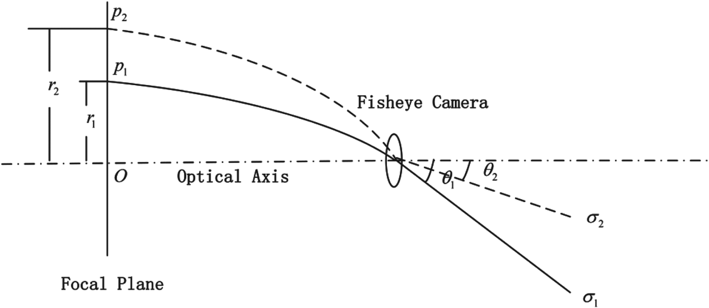
Due to the existence of optical distortion, the actual projection formula is not as shown in Equation (3). Distortions generally include radial distortion, decentring distortion, and in-plane distortion but in the final image, the radial distortion is the main problem. The decentring distortion and in-plane distortion are very small and can be neglected. In the case of only considering the radial distortion, the f distance error between the projection point of the celestial body and the principal point could be expressed as the error of the semiangular field of the corresponding celestial body as shown in Figure 1. Ideally, following the equisolid projection model, the celestial body σ 1 would project at p 2 on the focal plane, but due to the impact of radial distortion, it was actually projected at p 1. Correspondingly, the radius was changed from r 2 to r 1 (Yuan, Reference Yuan2012).

Figure 1. Imaging radius error and semiangular field error.
As shown in Equation (3), the semiangular field θ is calculated according to the distance r between the projection point of the celestial object and principal point in the image plane. Due to the radius distortion, we introduce a distortion model as
 $$\theta = 2\arcsin \left( {\displaystyle{r \over {2f}}} \right) + k_1 \left( {\arcsin \left( {\displaystyle{r \over {2f}}} \right)} \right)^2 + k_2 \left( {\arcsin \left( {\displaystyle{r \over {2f}}} \right)} \right)^3 + k_3 \left( {\arcsin \left( {\displaystyle{r \over {2f}}} \right)} \right)^4 $$
Equation (4) is the fisheye camera equisolid projection polynomial distortion model.
3. DETERMINATION OF HORIZONTAL DATUM
In celestial navigation, navigators use the angles between the horizon and stars, the Sun, the Moon, etc. to calculate AVP. When using a sextant for celestial navigation, this not only requires manual operation, but the navigator cannot observe the horizon line clearly in the dark at night, so celestial navigation is normally only carried out at twilight. To increase observation opportunities, use has been made of bubble levels, inertial units and other external devices to provide a horizontal datum, but this can result in a celestial navigation system becoming more complex and expensive. In this paper, we image stars and the horizon simultaneously by the use of fisheye camera and the obliquity of the camera was calculated according to the image coordinates and the shape of the horizon line. This method not only achieved automated determination of horizontal datum, but also provided the possibility of miniaturizing the celestial navigation system without the use of external devices.
3.1. Horizon Line Projection
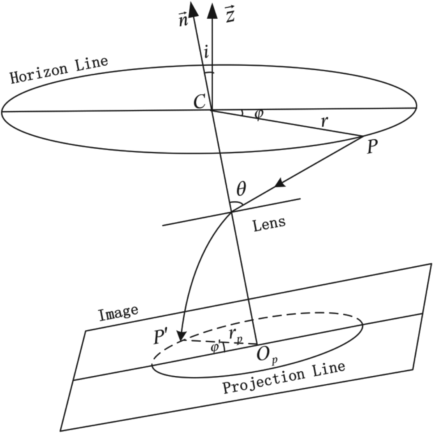
The horizon line, which is assumed as a circle orthogonal to the gravity vector, provides a surrogate for a vertical reference on the fisheye camera. Suppose in the sea, the height of imaging centre is h, and the Earth radius is R. Then the projection principle of the horizon line is shown in Figure 2.

Figure 2. Projection Principle of Horizon Line.
In Figure 2, ![]() $\vec n$ is the unit principal optical axis vector of the lens,
$\vec n$ is the unit principal optical axis vector of the lens, ![]() $\vec z$ is the unit local vector pointing in the opposite direction to gravity, the angle between them is denoted as i. C denotes the imaging centre of the fisheye camera. Now assume that P(x, y) is a point on the horizon line, the argument and semiangular field of which are φ and θ respectively. The corresponding projection point in the image plane is P′, the argument of which is φ′, the distance between P′ and O P is r′. Then according to the projection principle, θ could be calculated as
$\vec z$ is the unit local vector pointing in the opposite direction to gravity, the angle between them is denoted as i. C denotes the imaging centre of the fisheye camera. Now assume that P(x, y) is a point on the horizon line, the argument and semiangular field of which are φ and θ respectively. The corresponding projection point in the image plane is P′, the argument of which is φ′, the distance between P′ and O P is r′. Then according to the projection principle, θ could be calculated as
in which the argument φ in the horizontal plane could be calculated according to the corresponding argument φ′ in the image plane
 $$\varphi = \left\{ {\matrix{ {\arctan \left( {\tan (\varphi ' - \varphi _0 )\cos i} \right) - \pi} & { - \pi \leqslant \varphi \lt - \displaystyle{\pi \over 2}} \cr {\arctan \left( {\tan (\varphi ' - \varphi _0 )\cos i} \right)} & { - \displaystyle{\pi \over 2} \leqslant \varphi \leqslant \displaystyle{\pi \over 2}} \cr {\arctan \left( {\tan (\varphi ' - \varphi _0 )\cos i} \right) + \pi} & {\displaystyle{\pi \over 2} \lt \varphi \leqslant \pi} \cr}} \right.$$
Here, φ 0 is the angle between the shortest radius and the X-axis of image coordinate. According to Equation (4), we know the shortest radius equipollent to the least semiangular field θ, which indicates the inclination direction of the principal optical axis. Therefore, we can obtain the relationship between the semiangular field θ and the argument φ′ according to Equations (5) and (6).
3.2. Horizon Line Fitting Algorithm
After obtaining the images by fisheye camera, we can obtain the edge pixels of the horizon line in the images by utilizing an edge detection algorithm. In the image plane, if the coordinates of the principal point are (x 0, y 0), so for any one of the edge pixels, the distance from the principal point to it could be calculated according to Equation (2), and then the corresponding cosine values of the semiangular field could be calculated according to Equation (4)
However, according to the deduction in Section 3.1, we know the theoretical cosine values of θ is
Here, φ can be calculated by Equation (6). Therefore, an error equation can be established according to the corresponding theoretical values and the observed values as
in which, the error equation contains two unknown parameters, one of which is the estimated obliquity ![]() $\hat i$ of the principal optical axis, and the other is the estimated angle
$\hat i$ of the principal optical axis, and the other is the estimated angle ![]() $\hat \varphi _0 $ between the shortest radius and the X-axis of image coordinate. Linearizing Equation (9), and taking the initial value i 0 and φ 00 for the two unknown parameters, the error equation can be represented as
$\hat \varphi _0 $ between the shortest radius and the X-axis of image coordinate. Linearizing Equation (9), and taking the initial value i 0 and φ 00 for the two unknown parameters, the error equation can be represented as
in which, A denotes the coefficient matrix, ![]() $\delta \hat X$ denotes the correction vector of unknown parameters, L denotes the free term vector of the error equation, V denotes the residual vector. These can be represented as
$\delta \hat X$ denotes the correction vector of unknown parameters, L denotes the free term vector of the error equation, V denotes the residual vector. These can be represented as
 $$A = \left[ {\matrix{ {a_1} & {b_1} \cr {a_2} & {b_2} \cr \cdots & \cdots \cr {a_n} & {b_n} \cr}} \right]\quad \delta \hat X = \left[ {\matrix{ {\delta \hat i} \cr {\delta \hat \varphi _0} \cr}} \right]\quad \delta \hat X = \left[ {\matrix{ {\delta \hat i} \cr {\delta \hat \varphi _0} \cr}} \right]\quad V = \left[ {\matrix{ {v_1} \cr {v_2} \cr {....} \cr {v_n} \cr}} \right]$$
with
 $$a_j = \displaystyle{ {R\sin ^2 i\sin \varphi \tan (\varphi '_j - \varphi _0 ) + (R\cos i\cos \varphi + \sqrt {h^2 + 2Rh} \sin i)(1 + (\tan (\varphi '_j - \varphi _0 )\cos i)^2 )} \over {(R + h)(1 + (\tan (\varphi '_j - \varphi _0 )\cos i)^2 )}}$$
In Equation (14), cos θ j can be calculated according to Equation (8), and cos θ j′ can be calculated according to Equation (7). Based on the least square method, the estimated correction vector of unknown parameters can be solved as
and then the parameters ![]() $\hat i$ and
$\hat i$ and ![]() $\hat \varphi _0 $ are
$\hat \varphi _0 $ are
According to Equations (16) and (17), we can obtain the estimated obliquity ![]() $\hat i$ of the principal optical axis and the estimated angle
$\hat i$ of the principal optical axis and the estimated angle ![]() $\hat \varphi _0 $.
$\hat \varphi _0 $.
4. ASTRONOMICAL VESSEL POSITION DETERMINATION ALGORITHM
To determine the AVP, we must provide the altitudes of celestial bodies, which could be resolved by the star pixels in the image and the obliquity of the principal optical axis. Due to the super-wide FOV of the fisheye camera, generally about 100 stars can be imaged and traditional algorithms are not able to determine the AVP directly; a direct computation algorithm was established based on the least squares (LS) method.
4.1. Calculation of Celestial Altitude
According to the projection model of the fisheye camera and the obliquity of the principal optical axis, the celestial bodies were projected on different pixels in the image plane. Therefore we can compute the altitude of the corresponding celestial body by their image coordinates through a series of coordinate transforms. The coordinate systems include image coordinate system, projection coordinate system, camera coordinate system, and horizon coordinate system.
4.1.1. Transformation from image coordinate system to projection coordinate system
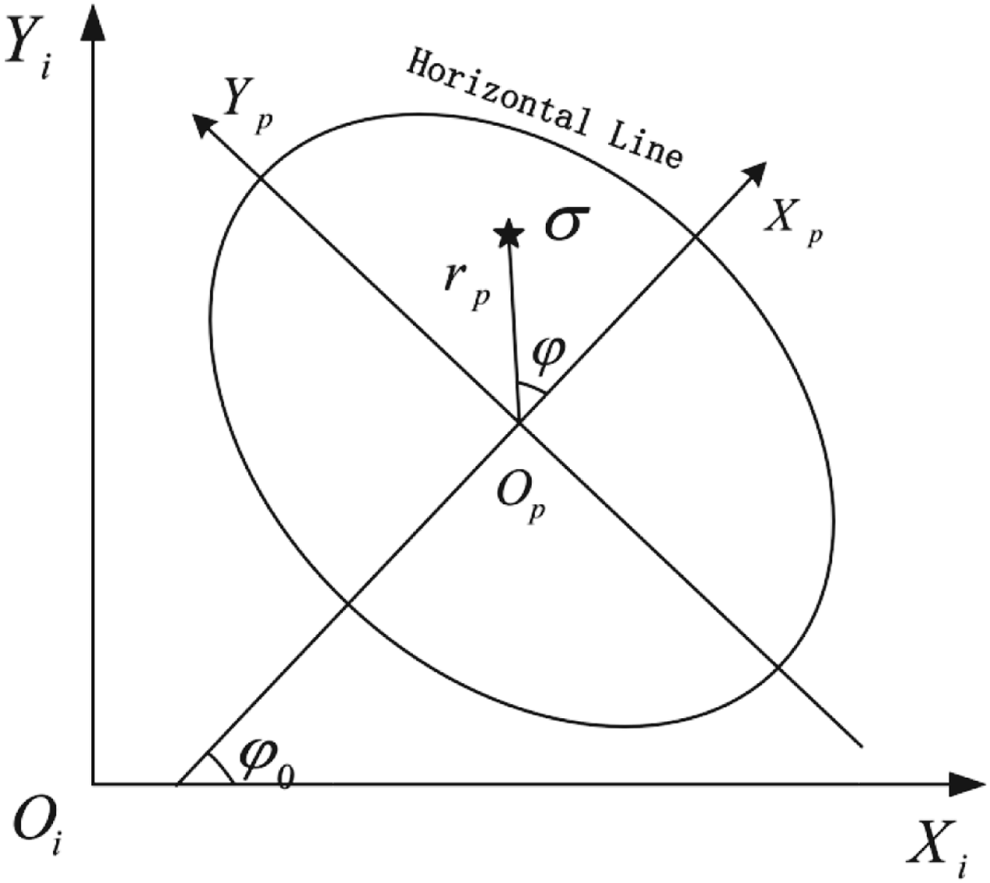
The image coordinate system is defined as O i-XiYi shown in Figure 3, its origin O i is the lower left corner of the image, and the coordinate of a celestial body could be denoted as (x i, yi). The projection coordinate system is defined as O p-XpYp, its origin O p(x oi, yoi) is the principal point of the fisheye camera, the axis X p is in parallel with the shortest radius of horizon line from the principal point, and the axis Y p is correspondingly the orthogonal direction to establish a right-hand coordinate with X p. The coordinate transformation of a celestial body from (x i, yi) to (x p, yp) demands two steps, the first step is the translation of the origin point from O i to O p, and the second step is a counter clockwise rotation for φ 0. This transformation can be represented as
in which, x oi and y oi are respectively the abscissa and ordinate of the principal point O p(x oi, yoi) in the image coordinate system, they are contained in the fisheye camera parameters and are known. x i and y i are respectively the abscissa and ordinate of the stars in the image coordinate system, they need to be extracted from the image by specific algorithm.

Figure 3. Image coordinate system and projection coordinate system.
4.1.2. Transformation from projection coordinate system to camera coordinate system
The radius of the horizon line from the principal point corresponds to the semiangular field, so to transform the coordinate of a celestial body from the projection coordinate system to the camera system, we transform the coordinate from Cartesian coordinate (x p, yp) to the polar form (φ, r p). This transformation can be expressed as
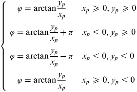 $$\left\{ \matrix{\matrix{ {\varphi = \arctan \displaystyle{{y_p} \over {x_p}}} & {x_p \geqslant 0,y_p \geqslant 0} \cr {\varphi = \arctan \displaystyle{{y_p} \over {x_p}} + \pi} & {x_p \lt 0,y_p \geqslant 0} \cr} \cr \matrix{ {\varphi = \arctan \displaystyle{{y_p} \over {x_p}} - \pi} & {x_p \lt 0,y_p \lt 0} \cr {\varphi = \arctan \displaystyle{{y_p} \over {x_p}}} & {x_p \geqslant 0,y_p \lt 0} \cr} } \right.$$
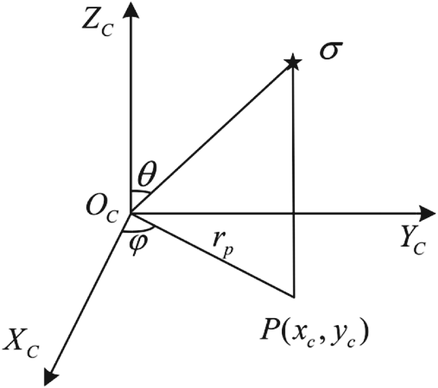
 The camera coordinate system is defined as a three-dimensional coordinate system O C-XCYCZC, its origin point O C is also the principal point of the fisheye camera, the axis X C is in parallel with X p, the axis Y C is in parallel with Y p, and the axis Z C is in parallel with the unit principal optical axis vector ![]() $\vec n$, which is shown in Figure 4.
$\vec n$, which is shown in Figure 4.

Figure 4. Camera coordinate system.
As for a point P(x c, yc) on the image plane projected by the celestial body σ, in the camera coordinate system, its corresponding argument and semiangular field are φ and θ respectively, and θ is correlative with the radius r p. According to the projection polynomial model Equation (7), θ could be expressed as
 $$\theta = 2\arcsin \left( {\displaystyle{{r_P} \over {2f}}} \right) + k_1 \left( {\arcsin \left( {\displaystyle{{r_P} \over {2f}}} \right)} \right)^2 + k_2 \left( {\arcsin \left( {\displaystyle{{r_P} \over {2f}}} \right)} \right)^3 + k_3 \left( {\arcsin \left( {\displaystyle{{r_P} \over {2f}}} \right)} \right)^4 $$
Since we have obtained the corresponding argument and semiangular field (φ, θ), we transform it into Cartesian coordinate (x c, yc, zc). Assuming that the sphere radius is one, the coordinate could be represented as
 $$\left\{ \matrix{x_c = \sin \theta \cos \varphi \cr y_c = \sin \theta \sin \varphi \cr z_c = \cos \theta } \right.$$
4.1.3. Transformation from camera coordinate system to horizontal coordinate system
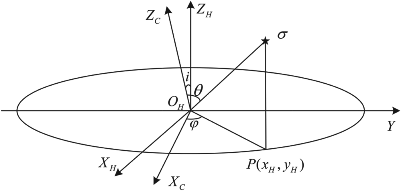
The horizontal coordinate system is defined as a three-dimensional coordinate system O H-XHYHZH, its origin point O H and Y-axis are the same as for the camera coordinate system, but the axis Z H is the local vector pointing to the opposite direction of gravity, and the axis X H correspondingly points to the orthogonal direction to establish a right-hand coordinate. Therefore, the angle between Z H and Z C is i. Now assuming that a point P(x H, yH) on the horizon line, the argument and semiangular field are respectively φ and θ. (Figure 5)

Figure 5. Camera coordinate system and horizontal coordinate system.
The transformation from the camera coordinate system to the horizontal coordinate system only has a rotation for an angle −i, and thus the two coordinate systems coincide. The rotation matrix is
 $$R_Y (i) = \left[ {\matrix{ {\cos ( - i)} & 0 & { - \sin ( - i)} \cr 0 & 1 & 0 \cr {\sin ( - i)} & 0 & {\cos ( - i)} \cr}} \right] = \left[ {\matrix{ {\cos i} & 0 & {\sin i} \cr 0 & 1 & 0 \cr { - \sin i} & 0 & {\cos i} \cr}} \right]$$
therefore
 $$\left[ {\matrix{ {x_H} \cr {y_H} \cr {z_H} \cr}} \right] = \left[ {\matrix{ {\cos i} & 0 & {\sin i} \cr 0 & 1 & 0 \cr { - \sin i} & 0 & {\cos i} \cr}} \right]\left[ {\matrix{ {x_C} \cr {y_C} \cr {z_C} \cr}} \right]$$
Then translate it into horizontal angle L H and altitude h H
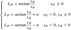 $$\left\{ {\matrix{ {L_H = \arctan \displaystyle{{y_H} \over {x_H}}} & {x_H \geqslant 0} \cr {L_H = \arctan \displaystyle{{y_H} \over {x_H}} + \pi} & {x_H \lt 0,y_H \geqslant 0} \cr {L_H = \arctan \displaystyle{{y_H} \over {x_H}} - \pi} & {x_H \lt 0,y_H \lt 0} \cr}} \right.$$
 $$h_H = \arctan \displaystyle{{z_H} \over {\sqrt {x_H ^2 + y_H ^2}}} $$
Finally, we obtain the horizontal angle L H and altitude h H of the celestial body, which will be used to determine the AVP.
4.1.4. Terrestrial refraction correction
We have calculated the horizontal angles and altitudes of celestial bodies according to the above steps, but because the light in the process of transmission will be affected by the influence of terrestrial refraction, we need to correct the altitude. The correction formula is
in which h 1 is the altitude of the celestial body after the correction for terrestrial refraction, and ρ is the correction, which may be calculated as
Here, L is a constant variable, the value of which is 1/273, t is the instantaneous Celsius temperature at the moment of observation, P is the instantaneous pressure at the moment of observation (mm Hg), and ρ 0 is the terrestrial refraction correction in the standard state. Currently the general approximate formula of ρ 0 is:
in which a=60·27″, b=−0·0669″. Furthermore, the dip of the altitudes also may be corrected, which can be calculated as
in which H is height of camera from horizontal, and the unit of dip is degree. So the altitude h after the correction can be calculated as
4.2. Solving the Astronomical Vessel Position
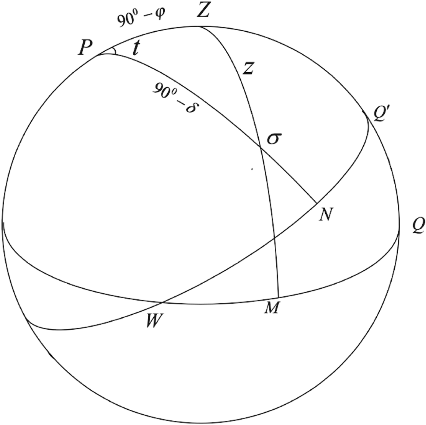
After the above steps, the celestial bodies' horizontal angle and altitude have been calculated. Additionally, with the observation time of and theoretical apparent position of celestial bodies, the vessel's astronomical longitude and latitude can be solved. On the celestial sphere, the north celestial pole P, the zenith Z, and a celestial body σ constitute a spherical positioning triangle, which is shown in Figure 6.

Figure 6. Spherical positioning triangle.
In Figure 6, WNQ′ is the celestial equator, WMQ is the horizon circle, and W is the west point. According to the side cosine formula of spherical trigonometry, we can obtain the relationship between zenith distance z, astronomical longitude λ, astronomical latitude φ, celestial body's right ascension α, declination δ, and hour angle (HA) t as
in which, the zenith distance z can be calculated from the celestial altitude
and the hour angle (HA) t can be calculated as
Here, S is the Greenwich true sidereal time at the moment of observation, which could be obtained through Universal Time Coordinated (UTC) time T. Firstly, according to the time bulletin A of the International Earth Rotation and Reference Systems Service (IERS), UTC time T adds on the time difference between UT 1 and UTC can obtain the UT 1 time T′, then transform it into mean sidereal time, and finally add on the nutation Δu (Δu=Δψcosε, Δψ is the nutation of ecliptic longitude, and ε is the obliquity of the ecliptic), we can transform it into true sidereal time S. The celestial body's right ascension α and declination δ can be calculated through an apparent position calculation program. Zenith distance z and time T (or T′) can be obtained through observation.
Thus, there are only two parameters λ and φ that remain unknown; the vessel's astronomical longitude and latitude can be solved by observing only two celestial bodies. As the terrestrial refraction cannot always be completely corrected, there is a systematic error in the zenith distance z. Therefore, a tiny parameter Δz should be added, then the zenith distance of the observation should be expressed as z+Δz, consequently, at least three celestial bodies are needed to calculate the three parameters (Li et al., Reference Li, Zheng, Li, Yu and Wang2013).
Set Δλ as the difference between vessel's longitude λ and its initial value λ 0, namely
Set Δφ as the difference between vessel's latitude φ and its initial value φ 0, namely
The equation only needs to calculate three parameters Δλ, Δφ and Δz. If there are n observations, set λ 0 and φ 0 as the initial values of longitude and latitude to linearize Equation (32), we can obtain
Here, V denotes a n dimensional residual vector, A denotes an n×t order coefficient matrix, ![]() $\delta \hat X$ denotes a n dimensional parameter vector, and L denotes a n dimensional observation vector. They can be expressed as
$\delta \hat X$ denotes a n dimensional parameter vector, and L denotes a n dimensional observation vector. They can be expressed as
 $$V = \left[ {\matrix{ {v_1} \cr {v_2} \cr \vdots \cr {v_n} \cr}} \right]\quad \delta \hat X = \left[ {\matrix{ {{\rm \Delta} \varphi} \cr {{\rm \Delta} \lambda} \cr {{\rm \Delta} z} \cr}} \right]\quad A = \left[ {\matrix{ {a_1} & {b_1} & 1 \cr {a_2} & {b_2} & 1 \cr \vdots & \vdots & 1 \cr {a_n} & {b_n} & 1 \cr}} \right]\quad L = \left[ {\matrix{ {l_1} \cr {l_2} \cr \vdots \cr {l_n} \cr}} \right]$$
in which
 $$a_i = \displaystyle{{\cos \varphi _0 \sin \delta _i - \sin \varphi _0 \cos \delta _i \cos t_i} \over {\sqrt {1 - P_{i0}^2}}} $$
 $$b_i = \displaystyle{{ - \cos \varphi _0 \cos \delta _i \sin t_i} \over {\sqrt {1 - P_{i0}^2}}} $$
The least-squares solution of Equation (37) is
The parameter vector ![]() $\delta \hat X$ can be calculated according to Equation (43), but some of the observations may have outliers, which should be detected and removed to obtain a reliable positioning solution. Therefore a robust estimation method is introduced to improve the positioning accuracy, which can assign zero weights to outliers, carrying down the weights for those large error observations, and taking full advantage of the high-precision observation information (Knight et al., Reference Knight, Wang and Rizos2010; Yang, Reference Yang1999). The robust estimation of unknown parameters is as follows
$\delta \hat X$ can be calculated according to Equation (43), but some of the observations may have outliers, which should be detected and removed to obtain a reliable positioning solution. Therefore a robust estimation method is introduced to improve the positioning accuracy, which can assign zero weights to outliers, carrying down the weights for those large error observations, and taking full advantage of the high-precision observation information (Knight et al., Reference Knight, Wang and Rizos2010; Yang, Reference Yang1999). The robust estimation of unknown parameters is as follows
Comparing Equation (44) with Equation (43), the weight matrix P is changed into equivalent weight matrix ![]() $\bar P$, which can be calculated as
$\bar P$, which can be calculated as
 $$\bar p\left( {\tilde v_i} \right) = \left\{ {\matrix{ 1 & {\left| {\tilde v_i} \right| \leqslant k_0} \cr {\displaystyle{{k_0} \over {\left| {\tilde v_i} \right|}}\left( {\displaystyle{{k_1 - \left| {\tilde v_i} \right|} \over {k_1 - k_0}}} \right)^2} & {k_0 \leqslant \left| {\tilde v_i} \right| \leqslant k_1} \cr 0 & {k_1 \leqslant \left| {\tilde v_i} \right|} \cr}} \right.$$
in which, the value of k 0 and k 1 is respectively 1·5 and 3·0, ![]() $\tilde v_i $ is for standardization residual, which is
$\tilde v_i $ is for standardization residual, which is
 $$\tilde v_i = \displaystyle{{v_i} \over {\sigma _0 \sqrt {\displaystyle{1 \over {\,p_i}} - A_i (A^T PA)^{ - 1} A_i ^T}}} $$
Here, v i is observation residual, σ 0 is unit weight and could be replaced as an empirical value, p i is the original weight of observations, A i is the i line of the matrix A.
The robust estimation of ![]() $\delta \hat X$ can be calculated according to Equations (44), (45) and (46) and the vessel's longitude λ and latitude φ can be calculated according to Equations (35) and (36).
$\delta \hat X$ can be calculated according to Equations (44), (45) and (46) and the vessel's longitude λ and latitude φ can be calculated according to Equations (35) and (36).
5. EXPERIMENTAL ANALYSIS
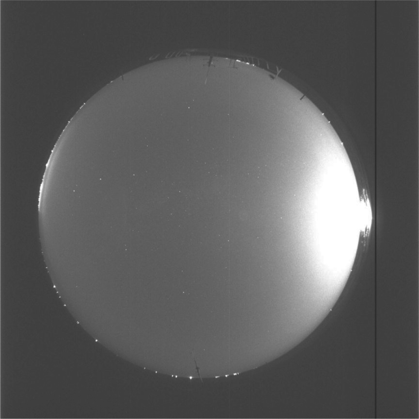
On 31 October 2012, we conducted an AVP determination experiment at Rizhao at sea by utilizing the fisheye camera. The size of the metal vessel used for the experiment was about 30 metres in length and 4 metres wide, and the displacement of the vessel was about 100 tonnes. We took the vessel about 15 nautical miles off the coast and anchored the vessel. Then we fixed the fisheye camera on the deck and connected it to a notebook PC. Finally, we set the exposure time of the fisheye camera as 0·2 seconds and to continuously shoot 30 images. Because the transit time for each image by USB 2.0 interface is approximately 12 seconds, this took a total of about 6 minutes. The first image is shown in Figure 7.

Figure 7. Image of stars and horizon.
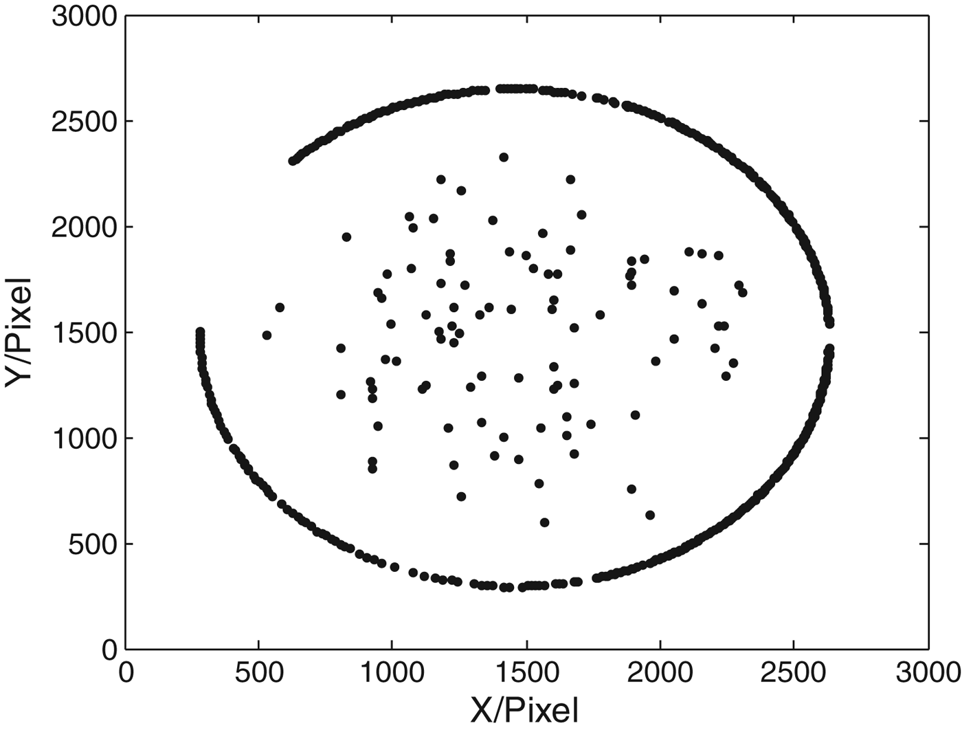
In Figure 7, the bright part of the image in the inner area is the pixels projected by the sky, and the dark part of the image in the surrounding area is a combination of the pixels projected by the seawater and the external FOV of the lens. Therefore, the intersect circle between the two parts is the horizon, and the bright points projected on it are from some lights of other ships at sea. Correspondingly, the bright pixels in the sky area are projected by the stars, and the lighter area on the right side of the image is projected by the moon and its halo. We retrieved the pixels of the stars and the horizon line from this image, which were shown in Figure 8.

Figure 8. Pixels of stars and horizon line.
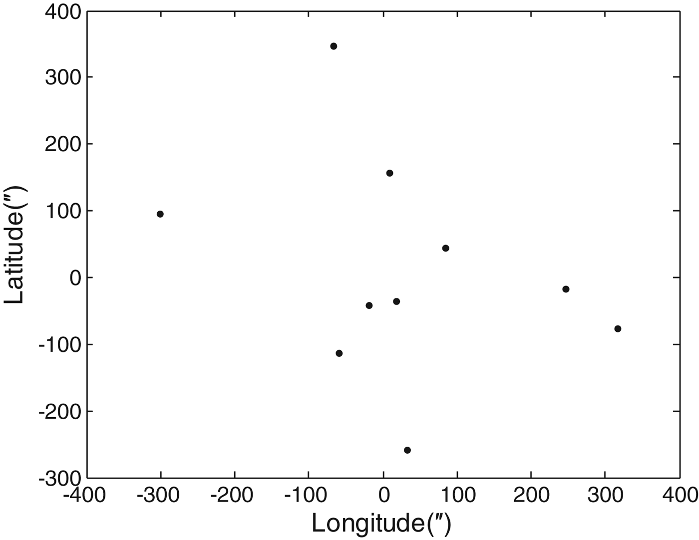
We extracted the pixels of stars and horizon line utilizing the algorithms as mentioned above in all of these 30 images, and then selected the top ten images according to the number of stars in each image to determine the AVP respectively. At the same time of shooting, we determined the vessel's longitude and latitude (λ=119·787647°E, φ=35·400817°N) by Global Positioning System (GPS) observations, and set them as the vessel's true position. Finally we compared the ten AVPs determined by the ten images with the vessel's true position, and obtained the AVP errors of each image shown in Figure 9.

Figure 9. Error of astronomical vessel position.
In Figure 9, each point represents an AVP error relative to the true position determined by GPS, and they are arranged in detail in Table 1.
Table 1. Errors of Astronomical Vessel Position.
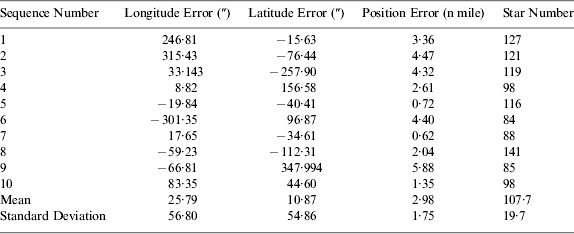
As can be seen from Figure 9 and Table 1, the numbers of stars extracted from the ten images are approximately 100, which indicated that the fisheye camera greatly increased the number of observations. Using the method described in this paper we could determine the AVP, and when comparing the average position of the ten images with the GPS position, the longitude error is only 25·79″ and the latitude error is only 10·87″; the corresponding position error is approximately 0·40 nautical miles and its standard deviation is about 1·32 nautical miles, which indicates that when using ten images to solve the average AVP, the position error is about 0·40±1·32 nautical miles. On the other hand, the average position error of the ten images is approximately 2·98 nautical miles and its standard deviation is about 1·75 nautical miles, which indicates that when using only one image to solve the AVP, the position error is about 2·98±1·75 nautical miles.
6. CONCLUSION
This paper has proposed a type of AVP determination method that utilises an optical fisheye camera to image celestial bodies and horizon simultaneously. This method firstly extracts the pixels of celestial bodies and the horizon line. It then fits the pixels projected by the horizon line to solve the obliquity of the fisheye camera's principle optical axis, calculates the altitude of the observations by the obliquity of the fisheye camera's principal optical axis and the image coordinates of celestial bodies. Finally, the spherical triangle method is used to deal with all the altitudes and the AVP is determined. The experiment results indicated that if using a single image to determine AVP, the position error is about 3 nautical miles, and if using ten images, the corresponding position error is about 0·5 nautical miles. When compared with the traditional methods, this method has the following significant advantages.
• Automated observation and processing. A sextant requires manual operation, but this method only requires the use of an optical fisheye camera to automatically shoot a single image, and then the AVP could be determined by computer algorithms automatically.
• Increased period of observation. A sextant can only be used in twilight in order to ensure that the celestial bodies and the horizon line can be seen simultaneously, but the fisheye camera has a high sensitivity, so it can be used during the whole night. Moreover, it could be used to observe the sun in the daytime and observe the moon, identified planets, and stars at night, so it has a 24-hour capability.
• High efficiency. Even a skilled navigator utilising a sextant to determine the AVP by observing 2–3 stars will generally need 15 minutes. However, when utilising the fisheye camera, it only needs 0·2 seconds of exposure time, about 11 seconds of image transmission time, and approximately 1 second of processing time; a total of less than 13 seconds. When using a USB3·0 interface to transmit images, this method to determine the AVP can be reduced to less than 2 seconds. Furthermore, it has the potential to realize real-time celestial navigation.
• System Miniaturization. This AVP determination method relies on the image of the horizon line to provide a level benchmark, so no bubble level and other external benchmark are needed. The equipment needed for this method is just a fisheye camera and a notebook PC. If a microprocessor was used instead of the notebook PC, the system could realize even further miniaturization.
In the experiment, the image sensor used is a 900-megapixel CCD sensor, and the AVP accuracy of a single image is equivalent to that of the sextant, the average AVP accuracy of ten images is significantly higher than that of the sextant. Consequently, with the development of the image sensor, its resolution will be further improved, and the positioning accuracy could also be further improved.
ACKNOWLEDGEMENTS
The authors would like to thank the Natural Science Foundation of China (NO. 41174025) for its financial support.


