Introduction
The Vibrant Soundbridge was developed as an active middle-ear implant to transmit vibration into the inner ear. It was originally coupled to the long process of the incus. However, the choice of coupling site now depends mainly upon intra-operative findings.
Three principal applications for the Vibrant Soundbridge have been described.
The first, original use of the Vibrant Soundbridge was over the oval window niche.Reference Lenarz, Weber, Mack, Battmer and Gnadeberg1 However, in order to extend its applications to include changes of the ossicular chain (e.g. interruption of the incudostapedial joint, necrosis or a gracile long process of the incus), the attachment point of the floating mass transducer component of the Vibrant Soundbridge has been modified. Different authors have described various modifications, including attachment of the floating mass transducer to the stapes suprastructure,Reference Wollenberg, Beltrame, Schonweiler, Gehrking, Nitsch and Steffen2, Reference Frenzel, Hanke, Beltrame, Steffen, Schonweiler and Wollenberg3 and interposition of cartilage between the tympanic membrane and a floating mass transducerReference Cremers, Verhaegen and Snik4 coupled to either a total ossicular replacement prosthesis (TORP) or a partial ossicular replacement prosthesis (PORP).Reference Huber, Ball, Veraguth, Dillier, Bodmer and Sequeira5, Reference Hüttenbrink, Zahnert, Bornitz and Beutner6 In the latter case, the floating mass transducer is integrated into a specially designed TORPReference Hüttenbrink, Zahnert, Bornitz and Beutner6 or PORPReference Huber, Ball, Veraguth, Dillier, Bodmer and Sequeira5 prosthesis. In some special cases of otosclerosis and mixed hearing loss, the floating mass transducer is additionally clipped onto the long process of the incus after the stapes has been substituted by a piston.Reference Venail, Lavieille, Meller, Deveze, Tardivet and Magnan7, Reference Dumon8
Secondly, the floating mass transducer may be coupled to the round window niche.Reference Wollenberg, Beltrame, Schonweiler, Gehrking, Nitsch and Steffen2, Reference Frenzel, Hanke, Beltrame, Steffen, Schonweiler and Wollenberg3, Reference Colletti, Soli, Carner and Colletti9–Reference Kiefer, Arnold and Staudenmaier13 This has been hypothesised to produce two effects: (Reference Lenarz, Weber, Mack, Battmer and Gnadeberg1) bypass of middle-ear pathology; and (Reference Wollenberg, Beltrame, Schonweiler, Gehrking, Nitsch and Steffen2) complete availability of amplification to effect basilar membrane displacement.Reference Fisch, Cremers, Lenarz, Weber, Babighian and Uziel14
A third approach has been used in a few cases: the floating mass transducer is coupled over a new, so-called third window into the cochlea.Reference Montag, Settevendemie, Helbig and Pau15 This approach is used in patients with combined obliteration of the oval and round window niches, generally due to tympanosclerosis. In contrast to the cochleostomy performed in cochlear implant surgery, the membranous inner ear remains intact. The floating mass transducer is coupled to the membrane or to a thin bone layer over the membranous inner ear.
The specific aim of this article is to demonstrate the technique and clinical application of vibroplasty in which the floating mass transducer is coupled directly to the oval window niche, in patients with a mobile stapes footplate but a malformed or destroyed stapes suprastructure.
Patients and surgical interventions
Seven patients with mixed hearing loss (five women and two men; mean age 53 ± 15 years; age range 25–69 years) underwent middle-ear surgery involving attachment of a Vibrant Soundbridge (MedEl, Innsbruck, Austria) in order to improve their hearing. All patients had undergone middle-ear surgery several years previously, as follows: open mastoid cavity without obliteration of the middle ear (n = 4); radical mastoidectomy (n = 1); and type III tympanoplasty in chronic, non-aerated middle ears with TORP (n = 5) or PORP (n = 2). However, post-operatively no patient received sufficient benefit from their surgery, and all suffered problems with conventional hearing. In addition, none of the patients received sufficient benefit from conventional hearing aids, and all rejected bone-anchored hearing aid implantation.
The seven patients' audiological data, prior to the surgery described below, are presented in Table I. Their air–bone gaps ranged from 26 to 51 dB.
Table I Pre-operative* audiometric findings for patients' implant candidate ear

Data represent hearing thresholds (dB HL) unless otherwise specified. *One day pre-operative. †Air–bone gap (ABG) for pure tone averages of 0.5, 1, 2 and 4 kHz. Pt no = patient number; BC = bone conduction; AC = air conduction
In these seven patients, it was decided to implant a Vibrant Soundbridge in the affected ears, and to couple the floating mass transducer directly to the oval window niche.
The first surgical steps were identical to those for conventional Vibrant Soundbridge implantation (i.e. involving coupling of the floating mass transducer to the long process of the incus). Depending on intra-operative findings and the effect of previous procedures (e.g. single or radical mastoidectomy changes, or residual cholesteatoma), surgery was completed to achieve a dry ear. In cases which had undergone previous mastoidectomy but with an intact canal wall, a posterior tympanotomy via the large facial recess was performed.
In three of the seven cases, the round window niche was completely exposed in order to verify efficient transmission of vibration. In all cases, a precondition of Vibrant Soundbridge implantation was visualisation of the round window reflex while touching the stapes footplate. In three cases, wider exposure was necessary for better visual control. The presence of the round window reflex was vital for the success of Vibrant Soundbridge implantation, and the procedure was abandoned if the reflex was absent.
During surgery, absence of stapes footplate fixation was apparent in all patients, while partial destruction of the stapes suprastructure was seen in four patients. In one patient, who had previously undergone tympanoplasty with PORP insertion, thinned stapes crura were found. In all patients, the facial nerve was covered by bone.
In order to achieve better coupling of the floating mass transducer to the stapes footplate, the stapes crura were dissected, using carbon dioxide laser, and the stapes suprastructure removed. A commercially available probe device was used to check that the oval window niche was wide enough to allow insertion of the floating mass transducer. In patients with a narrow oval window niche, cochlear bone needed to be removed, opposite the facial nerve, to enable correct positioning of the floating mass transducer.
We then prepared a cartilage–perichondrium graft specimen (Figure 1) taken from either the tragus or the concha. The underlying concept was to create a soft tissue casing for the floating mass transducer, while also firmly connecting the transducer to a small, solid, cartilage ‘plunger’ attached to the stapes footplate. This was realised by removing almost all the cartilage from a larger piece of cartilage–perichondrium, leaving only a tiny island about half a millimetre in diameter. This cartilage plunger was placed on the stapes footplate, between the remnants of the crura, and the attached perichondrium was spread out on the promontory or the bony facial canal. After cutting off its titanium clip, the floating mass transducer was attached to this perichondrium ‘blanket’, exactly opposite the cartilage plunger (Figure 2). The floating mass transducer was then fixed in place by wrapping it in the perichondrium and placing a piece of cartilage on top of it, thus covering the whole arrangement (Figure 3). In cases of open mastoid cavities, the cable of the implant was covered with cartilage and/or bone pâté.

Fig. 1 The prepared perichondrium specimen with cartilage island (to be placed on the stapes footplate).

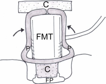
Fig. 2 Diagram showing the position of the autograft specimen (see Figure 1) on the stapes footplate (FP). The floating mass transducer (FMT) is attached to the perichondrium ‘blanket’ (P). C = cartilage

Fig. 3 Diagram showing the perichondrium (P) wrapped around the floating mass transducer (FMT), which is then covered with a piece of cartilage (C). FP = stapes footplate
Results
Figure 4 shows data for patients' mean unaided air conduction and bone conduction thresholds, and their median free field response (i.e. aided) thresholds, four months after implantation. Figure 5 shows patients' free field response air and bone conduction gains at frequencies between 250 Hz and 6 kHz. The differences between the air and bone conduction unaided thresholds and free field (aided) thresholds were compared.

Fig. 4 Comparison of the seven patients' mean unaided bone conduction (BC) and air conduction (AC) thresholds, versus their median free field response (FFR) (i.e. aided) thresholds, four months after surgery.

Fig. 5 The seven patients' bone and air conduction gain as a result of vibroplasty (subtracting median unaided threshold values from median free field response (i.e. aided) values).
The post-op discrimination of monosyllables at 65 dB was between 45–65 per cent. The post-op discrimination of polysyllables at 65 dB was between 80–100 per cent.
Discussion
Preliminary data from this study revealed that vibroplasty in which the floating mass transducer is coupled directly to the oval window niche resulted in similar audiological findings, compared with conventional coupling of the floating mass transducer to the long process of the incus. Attachment of the floating mass transducer onto the oval window niche requires the following preconditions: a mobile stapes footplate, a facial nerve covered with bone, and adequately wide access to the oval window niche. Audiological data published elsewhere by our department also indicate that post-operative results following vibroplasty involving coupling of the floating mass transducer to the oval window niche appear to be as good as those following vibroplasty involving coupling of the floating mass transducer to the round window.Reference Beltrame, Martini, Prosser, Giarbini and Streitberger11
In patients with mixed hearing loss but a mobile stapes footplate, there are some advantages to oval window niche stimulation compared with round window stimulation. Firstly, one can avoid exposure of the round window membrane, thus avoiding the associated risk of inner ear damage due to drilling close to this membrane,Reference Pau, Just, Bornitz, Lasurashvilli and Zahnert16 especially in situations where the round window opening is partially or completely covered by bone. Secondly, in patients with insufficient post-operative hearing improvement, the floating mass transducer can still be transferred to the round window. Thirdly, the oval window niche procedure involves less surgical complexity and expense, compared with the round window procedure.
• Vibromechanical stimulation of the inner ear via the oval window niche is a reliable procedure with which to improve hearing
• In patients with mixed hearing loss combined with a destroyed stapes suprastructure but a mobile stapes footplate, the authors recommend coupling of the floating mass transducer to the stapes footplate rather than the round window
• This procedure avoids the risk of inner ear damage associated with exposure of the round window membrane
Further studies are needed to assess the benefit derived from different coupling procedures (e.g. using cartilage or perichondrium on the stapes footplate); temporal bone laboratory research may be useful in this respect. In a separate paper, we will present our experimental data supporting the hypothesis that attachment of the floating mass transducer to a mobile stapes footplate yields similar results, compared with attachment to the long process of the incus.
Conclusions
Artificial vibromechanical stimulation of the inner ear via the oval window niche is a reliable procedure with which to improve hearing. In patients with mixed hearing loss combined with a destroyed stapes suprastructure but a mobile stapes footplate, we advocate attachment of the floating mass transducer component of a Vibrant Soundbridge to the stapes footplate rather than to the round window. This procedure reduces the risk of inner ear damage during exposure of the round window membrane.