


1. INTRODUCTION
Soft X-ray lasing from laser-plasmas has been a significant achievement for the application of high power infrared lasers (Tallents, Reference Tallents2003), while X-ray free-electron lasers are now an important advancement arising from electron accelerator technology (Ayvazyan, 2006). Applications for such lasers are developing (for example, Edwards et al., Reference Edwards, Whittaker, Mistry, Booth, Pert, Tallents, Rus, Mocek, Koslova, McKenna, Delserieys, Lewis, Notley and Neely2006, Reference Edwards, Whittaker, Tallents, Mistry, Pert, Rus, Mocek, Kozlová, Polan, Praeg, Stupka and Homer2007; Kuehl et al., Reference Kuehl, Ursescu, Bagnoud, Javorkova, Rosmej, Cassou, Kazamias, Klisnick, Ros, Nickles, Zielbauer, Dunn, Neumayer, Pert and Team2007; Neumayer et al., Reference Neumayer, Bock, Borneis, Brambrink, Brand, Caird, Campbell, Gaul, Goette, Haefner, Hahn, Heuck, Hoffmann, Javorkova, Kluge, Kuehl, Kunzer, Merz, Onkels, Perry, Reemts, Roth, Samek, Schaumann, Schrader, Seelig, Tauschwitz, Thiel, Ursescu, Wiewior, Wittrock and Zielbauer2005; Purvis et al., Reference Purvis, Grava, Filevich, Marconi, Dunn, Moon, Shlyaptsev, Jankowska and Rocca2007; Tallents et al., Reference Tallents, Booth, Edwards, Gartside, Whittaker, Zhai, Rus, Mocek, Koslova, Polan and Homer2009; Ziaja et al., Reference Ziaja, Weckert and Moller2007).
Plasma-based X-ray lasers and free-electron lasers operate without mirrors in amplified spontaneous emission (ASE) mode (Pert, Reference Pert1994). To improve the spatial uniformity, coherence, and irradiance of both plasma-based X-ray lasers and free-electron lasers, seeding the amplification with an injected pulse from, for example, high infrared laser harmonics has been investigated. Ditmire et al. (Reference Ditmire, Hutchinson, Key, Lewis, MacPhee, Neely, Perry, Smith, Wark and Zepf1995) originally demonstrated the injection and amplification of high harmonics with small gain at 25 nm wavelength in an extreme ultraviolet (EUV) amplifier, while Mocek et al. (Reference Mocek, Sebban, Maynard, Zeitoun, Gaivre, Hallou, Fajardo, Kazamias, Cros, Aubert, Lachèze-Murel, Rousseau and Dubau2005) used an injected seed beam to experimentally investigate the plasma gain dynamics of a gas cell plasma amplifier. Zeitoun et al. (Reference Zeitoun, Faivre, Sebban, Mocek, Hallou, Fajardo, Aubert, Balcou, Burgy, Douillet, Kazamias, De Lachèze-Murel, Lefrou, Le Pape, Mercère, Merdji, Morlens, Rousseau and Valentin2004) and Wang et al. (Reference Wang, Granados, Larotonda, Berrill, Luther, Patel, Menoni and Rocca2006) demonstrated injected harmonic amplification to saturation in plasma amplifiers at longer wavelength (33 nm). Earlier plasma-based X-ray laser experiments also showed that two plasma amplifiers could be operated in an injector amplifier arrangement (Carillon et al., Reference Carillon, Chen, Dhez, Dwivedi, Jacoby, Jaegle, Jamelot, Zhang, Key, Kidd, Klisnick, Kodama, Krishnan, Lewis, Neely, Norreys, O'Neill, Pert, Ramsden, Raucourt, Tallents and Uhomoibhi1992; Lewis et al., Reference Lewis, Neely, O'Neill, Uhomoibhi, Key, Hadithi, Tallents and Ramsden1992). Harmonic injection into a free-electron laser has now been demonstrated (Lambert et al., Reference Lambert2008).
Plasma-based X-ray lasers utilize a gain medium pumped transversely by a line focused infrared laser driver pulse (Tallents, Reference Tallents2003), pumped longitudinally by laser irradiation along a gas cell (Mocek et al., Reference Mocek, Sebban, Maynard, Zeitoun, Gaivre, Hallou, Fajardo, Kazamias, Cros, Aubert, Lachèze-Murel, Rousseau and Dubau2005), or electrically pumped by a capillary discharge (Rocca, Reference Rocca1999; Wagner et al., Reference Wagner, Eberl, Frank, Hartmann, Hoffmann and Tkotz1996). The problems of making a resonator at X-ray laser wavelengths are severe, so only single or double transit amplified spontaneous emission lasers have been employed. With transverse pumping by infrared laser, a pre-pulse is used to produce expanding plasma so that the ground state of the required Ne- or Ni-like ion is abundant in the expanding plasma. A second main pulse heats the pre-plasma causing collisional excitation and the production of a population inversion. The pre-pulse ensures that the density gradients are gentle, so that refraction of the X-ray laser beam is small. It also increases the gain medium volume and increases the pumping laser absorption. Further efficiency of X-ray laser pumping has been achieved using grazing incidence pumping (Keenan et al., Reference Keenan, Dunn, Patel, Price, Smith and Shlyaptsev2005). Here a beam is incident into preformed plasma at a grazing angle. The main advantage (Keenan et al., Reference Keenan, Dunn, Patel, Price, Smith and Shlyaptsev2005; Tűmmler et al., Reference Tűmmler, Janulewicz, Priebe and Nickles2005) of the grazing incident pumping is that the pumping geometry improves laser coupling efficiency into an optimum gain region of plasma, using refraction to turn the pumping laser at an electron density below the critical density where gain production is maximized. Plasma-based X-ray lasers have poor transverse spatial uniformity and coherence with for short duration pumping (<10 ps), a typical profile consisting of a complex speckle pattern (Guilbaud et al., Reference Guilbaud, Klisnick, Cassou, Kazamias, Ros, Jamelot, Joyeux and Phalippou2006) with each speckle associated with amplification of a single spontaneously emitted photon. The longitudinal coherence is close to the Fourier transform limit (Mistry et al., Reference Mistry, Edwards and Tallents2006). Seeding of the amplification can allow much more spatially uniform and coherent laser output as long as the amplification of the seeded beam dominates ASE (the subject of this paper). Using Maxwell-Bloch simulations, recent work by Al'miev et al. (Reference Al'miev, Larroche, Benredjem, Dubau, Kazamias, Möller and Klisnick2007) has shown that short duration, broad bandwidth harmonic radiation injected into a plasma amplifier with a narrow gain bandwidth leads to an amplified output pulse of temporal duration consistent with the gain bandwidth rather than the harmonic bandwidth.
The original concept for a free-electron laser (FEL) was proposed by Madey (Reference Madey1971). Elias (Reference Elias, Fairbank, Madey, Schwettman and Smith1976) demonstrated that light generated by an electron beam oscillation in a magnetic field can be amplified by stimulated emission. Free-electron lasers use an electron accelerator to produce an electron beam. The electrons arrange themselves into “micro-bunches” and interact with the developing laser electric field so that the laser electric field is coherently additive at each spatial point (Tallents, Reference Tallents2008). Free-electron lasing is achieved with single-pass, high-gain self-amplified spontaneous emission (SASE) (Milton et al., Reference Milton, Gluskin, Arnold, Benson, Berg, Biedron, Borland, Chae, Dejus, Hartod, Deriy, Erdmann, Eidelman, Hahne, Huang, Kim, Lewellen, Li, Lumpkin, Makarov, Moog, Nassiri, Sajaev, Soliday, Tieman, Trakhtenberg, Travish, Vasserman, Vinokurov, Wang, Wiemerslage and Yang2001; Ayvazyan et al., Reference Ayvazyan2006). FELs operated in SASE mode have a broad spectral bandwidth (ν/Δν ≤ 100) which means that very short (<1 fs) pulses can be produced, but using the beams for some experiments such as interferometry, where high longitudinal coherence is required, will be difficult. The longitudinal coherence of FELs is significantly improved by seeding the FEL amplifier with moderately spectrally narrow pulses generated by harmonics from optical lasers (Schwettman, Reference Schwettman1999; Yu et al., Reference Yu, Babzien, Ben-Zvi, Dimauro, Doyuran, Graves, Johnson, Krinsky, Malone, Pogorelsky, Skaritka, Rakowsky, Solomon, Wang, Woodle, Yakimenko, Biedron, Galayda, Jagger, Gluskin, Jagger, Sajaev and Vasserman2000, Lambert et al., Reference Lambert2008). The transverse coherence of FELs is only marginally improved by seeding, as unseeded FELs already have moderately good transverse coherence.
We consider here laser radiation transfer and gain in an amplifier following injection seeding of radiation assuming a single ray path following the ray optic treatment of Pert (Reference Pert1994). The relative strength of amplification of the injected irradiance relative to the ASE irradiance is examined so that the required irradiance of an injected pulse for an amplified injected beam to dominate ASE is estimated.
2. THEORY
When injected light is amplified, the amplifier self-emission is also amplified by ASE. ASE irradiance after integration over frequency and for a uniform amplifier of length L is given by Tallents (Reference Tallents2003)
![\eqalign{I_{ASEtot} &= \vint I_{ASE} \lpar \upsilon \rpar d \upsilon = I_0 \,f\lpar 0\rpar \vint \!\!\lcub \!\!\exp \lsqb G\lpar \upsilon \rpar L\rsqb - 1\rcub d\upsilon \cr &= I_0 \,f\lpar 0\rpar \vint \left\{\exp \left[GL {\,f\lpar \upsilon \rpar \over f\lpar 0\rpar }\right]- 1 \right\}d\upsilon\comma \; }](https://static.cambridge.org/binary/version/id/urn:cambridge.org:id:binary:20151022040714489-0722:S0263034609000500_eqn1.gif?pub-status=live)
where I 0f(0) = E(ν)/G(ν) for E(ν) the spontaneous emission per unit length, G(ν) is the gain coefficient at frequency ν and f(ν) is the small signal gain coefficient line shape function at frequency ν. We assume that ν = 0 is at the gain coefficient peak and that G represents the peak gain coefficient.
The amplified irradiance of an injected beam of peak spectral irradiance I Init into the same laser amplifier can be written as
![\eqalign{I_{Injtot} &= \vint I_{Inj} \lpar \upsilon\rpar d\upsilon = I_{Init} \vint {g\lpar \upsilon \rpar \over g\lpar 0\rpar } \exp \left[GL {\,f\lpar \upsilon \rpar \over f\lpar 0\rpar } \right]d\upsilon\cr &=I_{Init}^{tot} \vint g\lpar \upsilon\rpar \exp \left[GL {\,f\lpar \upsilon \rpar \over f\lpar 0\rpar } \right]d\upsilon\comma \; }](https://static.cambridge.org/binary/version/id/urn:cambridge.org:id:binary:20151022040714489-0722:S0263034609000500_eqn2.gif?pub-status=live)
where the initial spectrally integrated injected irradiance is given by
for g(ν) is the spectral line profile of the injected beam.
A homogeneously broadened gain profile G(ν) is related to the small signal gain coefficient at line center g 0 by
where I s is the saturation irradiance and I aν is the average irradiance. The average irradiance I aν, considering both ASE and the amplified injected beam, is given by

3. INJECTED AMPLIFICATION AND ASE
The ratio of the irradiance at output due to amplification of the injected beam to that due to ASE is given by
![R_{Inj/ASE} = {I_{Inj} \lpar \upsilon \rpar \over I_{ASE} \lpar \upsilon \rpar } = {I_{Init}^{tot} g\lpar \upsilon \rpar \exp \left[ GL \displaystyle{\,f\lpar \upsilon\rpar \over f\lpar 0\rpar} \right] \over I_0 \,f\lpar 0\rpar \exp \left[ GL \displaystyle{\,f\lpar \upsilon \rpar \over f\lpar 0\rpar} - 1 \right]}.](https://static.cambridge.org/binary/version/id/urn:cambridge.org:id:binary:20151022040714489-0722:S0263034609000500_eqn6.gif?pub-status=live)
We can approximate
for large gain length product GL. The average irradiance can thus be rewritten as
![\eqalign{I_{av} &= \vint \left\{\left[{\,f\lpar \upsilon\rpar \over \;f\lpar 0\rpar } I_{ASE} \lpar \upsilon \rpar \right]\lpar 1 + R_{Inj/ASE}\rpar \right\}d \upsilon. \cr &= I_{av}^{ASE} \lpar 1 + S\rpar \comma \; }](https://static.cambridge.org/binary/version/id/urn:cambridge.org:id:binary:20151022040714489-0722:S0263034609000500_eqn8.gif?pub-status=live)
where
![\eqalign{S &= {I_{Init}^{tot} \over I_0 \,f\lpar 0\rpar } {\vint \!g \lpar \upsilon \rpar I_{ASE} \lpar \upsilon \rpar d\upsilon \over I_{av}^{ASE}}\cr &= {I_{Init}^{tot} \over I_0 \,f\lpar 0\rpar } {\vint \left\{ \,f\lpar \upsilon\rpar g\lpar \upsilon\rpar \exp \left[ GL \displaystyle{\,f\lpar \upsilon \rpar \over f\lpar 0\rpar} - 1 \right] \right\} d\upsilon \over \vint \left\{ f\lpar \upsilon\rpar \exp \left[ GL \displaystyle{\,f \lpar \upsilon \rpar \over f\lpar 0\rpar} \right] - 1 \right\} d\upsilon}= {I_{Init}^{tot} \over I_0} S^{\prime}.}](https://static.cambridge.org/binary/version/id/urn:cambridge.org:id:binary:20151022040714489-0722:S0263034609000500_eqn9.gif?pub-status=live)
Noting the relationship between I ν and I s in Eq. (4), the effect of saturation on the amplification of the injected and ASE beams can be taken into account by adjusting the saturation irradiance in the formula determined by Pert (Reference Pert1994) and Casperson (Reference Casperson1977). We can write for the relationship between the actual gain coefficient G and the small signal gain coefficient (Pert, Reference Pert1994)
where I tot = I Injtot + I ASEtot for a single directional X-ray laser output. Here the effective saturation irradiance I′s is related to the actual saturation irradiance I s by
Eq. (10) then becomes
The ratio R out of the spectrally integrated irradiance due to the injected beam to that due to ASE is given by
![\eqalign{R_{out} &= {I_{Injtot} \over I_{ASEtot}} = {\vint \!I_{Inj} \lpar \upsilon \rpar d\upsilon \over \vint \!I_{ASE} d\upsilon}\cr &= {I_{Init}^{tot} \vint \left\{ g\lpar \upsilon\rpar \exp \left[ GL \displaystyle{\,f\lpar \upsilon \rpar \over f\lpar 0\rpar} \right] \right\} d\upsilon \over I_0 \,f\lpar 0\rpar \vint \left\{ \exp \left[ GL \displaystyle{\,f\lpar \upsilon \rpar \over f\lpar 0\rpar} \right] - 1\right\} d\upsilon}={I_{Init}^{tot} \over I_0} R_{out}^{\prime}.}](https://static.cambridge.org/binary/version/id/urn:cambridge.org:id:binary:20151022040714489-0722:S0263034609000500_eqn13.gif?pub-status=live)
Assuming Gaussian line profile shapes f(υ) and g(υ) for the gain coefficient and injected beam initial profile respectively and that the profiles f(υ) and g(υ) are centered on the same frequency, we can expand the exponentials as Taylor series in the formulae for R′out and S′ and integrate term-by-term. We obtain that
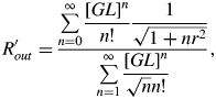
for r = ΔυInj/Δυp, the ratio of the width of the injected beam spectral profile to the gain coefficient spectral width. Values of R′out are plotted in Figure 1.

Fig. 1. (Color online) The reduced ratio of the irradiance at output due to amplification of the injected beam to that due to ASE as a function of the actual gain length product. Results are for different ratios r = 0.01, 0.1…(as labeled) of the spectral width of the injected beam to the gain coefficient.
To take account of saturation effects, we need to evaluate S′ (see Eq. (9)). As for R′out, we obtain
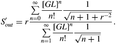
Values of S′out are plotted on Figure 2. The values of S = (I Inittot/I 0) S′out are used to account for saturation effects using Eqs (9) and (12). We see that for large r (as may be expected for harmonic injection) that saturation will occur at a lower amplified irradiance of the injected beam as S′out can be larger.

Fig. 2. (Color online) The parameter S′out relating the saturation behaviors of a plasma amplifier with and without an injected seed beam as a function of the gain length product for different values of r = 0.01, 0.1… (as labeled) of the spectral width of the injected beam to the gain coefficient width.
4. NUMERICAL RESULTS
An example of the output irradiance variation of an injected amplified pulse and ASE calculated using the above equations with I Inittot = I 0 for a relatively spectrally broad injected pulse is shown in Figure 3. The effect of the slow increase of the injected pulse irradiance at short lengths L as observed by Wang et al. (Reference Wang, Granados, Larotonda, Berrill, Luther, Patel, Menoni and Rocca2006) is clearly seen. The spectrally broad injected pulse spectrally narrows with increasing length at short lengths without significant increase of the spectrally integrated irradiance. For the example shown in Figure 3, ASE dominates the amplified injected pulse. Saturation of the ASE beam has a simultaneous saturation effect on the amplified injected beam at g 0L ≈ 15.

Fig. 3. (Color online) Relative spectrally integrated irradiance due to ASE (I ASEtot) and the amplification of an injected pulse (I Injtot) as a function of small signal gain coefficient length product. The ratio r of injected beam spectral bandwidth to the gain coefficient bandwidth is taken to be 100 here. It is also assumed for this plot that the injected pulse irradiance I Inittot = I 0 where I 0 is a measure of the irradiance of spontaneous emission (see text and figure 4). Saturation effects are modeled assuming a saturation irradiance such that I s/I 0 = 106.
The injected laser pulse normally needs to have irradiance I Inittot ≫ I 0 for the amplified injected beam to dominate ASE output (see the discussion below). The initial spontaneous emission irradiance can be written for a Gaussian shaped gain coefficient line profile as (Tallents, Reference Tallents2003)
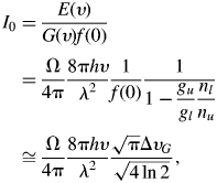
where Ω is the solid angle for which spontaneous photons can be amplified. Values of I 0 are plotted in Figure 4.

Fig. 4. (Color online) Spontaneous emission irradiance I 0 as a function of wavelength λ at particular solid angles Ω (in steradian) for emission and gain spectral bandwidth ΔυG = 10−4c/λ.
We can estimate the injected pulse energy E Init from a harmonic or other source required for amplification of the injected pulse to dominate over ASE. We require
and hence from Figure 1, require I Inittot> I 0r as R′out ≈ 1/r at large GL and large r. Assuming the amplification process is constant when present and ASE only occurs for the gain coefficient characteristic duration τ p, the injected pulse energy required for a time-integrated measurement to observe more output from the amplified injected pulse than from ASE is given by
where A is the amplifying cross-section area and τ Inj is the injected pulse duration after amplification (see Al'miev et al., Reference Al'miev, Larroche, Benredjem, Dubau, Kazamias, Möller and Klisnick2007). For typical laser-pumped plasma amplification with amplifying cross-section area A = 10−4 cm2, τ p = 10 ps, relative spectral bandwidth of the injected beam to the gain coefficient r = ΔυInj/Δυp = 100 and spontaneous emission irradiance I 0 = 103 Wcm−2 (see Fig. 4), we obtain E Init > 0.1 nJ. Harmonic output, for example, can be readily produced with E Init > 0.1 nJ (McNeil, Reference McNeil, Clarke, Dunning, Hirst, Owen, Thompson, Sheehy and Williams2007), so our results confirm that it is feasible to seed plasma amplifiers with harmonic output without a significant ASE contribution to the total laser output.
5. CONCLUSION
The relative irradiance of an amplified injected beam and ASE output from a laser amplifier has been examined. It has been shown that the spectrally integrated injected beam irradiance I Inittot needs to exceed the value of spontaneous emission irradiance I 0 (see equation (16)) by a ratio R′out. For larger gain length products G(0)L, the R′out values lie in the range 10−4 – 10 depending on the relative spectral widths r of the injected beam and amplifier gain coefficient. We can see that where the injected spectral width greatly exceeds the gain coefficient spectral bandwidth (at larger r = ΔυInj/Δυp), ![]() , while
, while ![]() , if the injected spectral width is much less than the gain coefficient bandwidth.
, if the injected spectral width is much less than the gain coefficient bandwidth.
ACKNOWLEDGEMENT
Funding has been provided by the UK Engineering and Physical Sciences Research.


