1. INTRODUCTION
Intense electron beam generation from laser plasma accelerators and conventional accelerators is a very active research topic due to numerous applications (Chen et al., Reference Chen, Unick, Vafaei-Najafabadi, Tsui, Fedosejevs, Naseri, Masson-Laborde and Rozmus2008; Kulagin et al., Reference Kulagin, Cherepenin, Hur, Lee and Suk2008; Zhang et al., Reference Zhang, Tang, Huang, Qu, Guan and Wang2008). Intense electron-beam accelerators (IEBA) based on Blumlein line (Liu et al., Reference Liu, Li, Zhang, Li and Wang2006) is widely used in a great variety of applications such as in lasers, high power microwave generators (Korovin et al., Reference Korovin, Kurkan, Logino, Pegel, Polevin, Volkov and Zherlitsyn2003), and X-ray generation (Coogan et al., Reference Coogan, Davanloo and Collins1990; Tarasenko et al., Reference Tarasenko, Shunailov, Shpak and Kostyrya2005), and so on. At present, high power is the most important development trend for applications of particle beams from accelerators (Hoffmann et al., Reference Hoffmann, Blazevic, Ni, Rosmej, Roth, Tahir, Tauschwitz, Udrea, Varentsov, Weyrich and Maron2005; Li et al., Reference Li, Yuan, Zhang, Shu and Zhang2008). However, increasing the duration of the output pulse and improving electron-beam quality is also important for the requirement of applications. Spiral PFL (Liu et al., Reference Liu, Yin, Ge, Zhan, Cheng, Feng, Shu, Zhang and Wang2007; Yatsui & Masugata, Reference Yatsui, Shimiya, Masugata, Shigeta and Shibata2005) and pulse-forming network are the common way to increase pulse width (Verson & Brion, Reference Verson and Brion2003; Lancaster et al., Reference Lancaster, Clark and Buttram1988). As early as the 1980s, the AVCO Research Laboratory of America constructed a single-pulse accelerator based on folded modified spiral PFL (Friedman et al., Reference Friedman, Limpaecher and Sirchis1988), and a pulse voltage of a megavolt was obtain in a 2Ω load for the design parameter. At the beginning of this century, the Institute of High Current Electronics of Russia combined a Tesla transformer with a spiral PFL of oil dielectric, which allowed the production of compact and reliable high-current beam accelerators (Korovin et al., Reference Korovin, Gubanov, Gunin, Pegel and Stepchenko2001). When a spark gas gap switch with forced gas circulation was utilized, at a repetition rate of 100 pulses per second, 130 ns, a 700 kV pulses were produced in a 150Ω load. Recently, an electron-beam accelerator based on strip spiral Blumlein line (SSBL) with water dielectric (Liu et al., Reference Liu, Yin, Ge, Zhan, Cheng, Feng, Shu, Zhang and Wang2007) was investigated. The field-emission diode voltage amounted to more than 500 kV, the electron beam current of the diode was about 24 kA, and the pulse duration was about 200 ns. Compared with the accelerator of traditional water Blumlein line, an electron-beam accelerator based on SSBL can increase the duration of the output pulse in the same geometrical dimension. But the disadvantage of the SSBL is the output voltage waveform on the matched load may be distorted, which influences the electron beam quality. So in this paper, according to the electromagnetic theory, formulas for calculating the main electric parameters of SSBL (inductance, capacitance, transmission time, and characteristic impedance) are deduced. The designed condition of SSBL for the output ideal voltage pulse on the matched load is obtained by theoretical analysis. In addition, the Karat code is used to simulate SSBL to get the output voltage waveform on the matched load, and the relationship between duration of the output pulse and spiral angel is obtained. At last, a couple of contrast experiments are performed on an IEBA based on SSBL with water dielectric. The experimental results accord with the theoretical and simulated results. The work in this paper is helpful to investigate and design IEBA based on SSBL.
2. THEORETICAL ANALYSES
Structure and electromagnetic field of the SSBL are more complicated than the traditional Blumlein line, so it is difficult to get the electric parameters of SSBL (inductance, capacitance, transmission time, and characteristic impedance of SSBL). Strictly speaking, the electric parameters of SSBL calculated by solving the Maxwell equations are dependent on the frequency. But for the convenience of engineering calculation, an approximate solution which does not depend on the frequency is useful. In case of the SSBL, the spiral cylinder is a structure of axial symmetry and the gap between the spiral strips is much shorter than the width of the spiral strip. Regarding the skin effect, the direction of the current on the spiral cylinder is along the spiral angle of the spiral strip. In such a designed case, we may suppose that the dispersion effect is not taken into account. The formulas for calculating inductance, capacitance, transmission time, and characteristic impedance of SSBL can be derived by the electromagnetic theory.
2.1. Calculation of Parameters of SSBL
The SSBL consists of an inner cylinder, a spiral strip middle cylinder, and an outer cylinder. r 1, r 2, and r 3 are the radii of the three cylinders, respectively, W is the width of the strip, δ is the distance between the spiral strips, φ is the spiral angle (Fig. 1).

Fig. 1. The structure of the SSBL.
In case of the designed SSBL, the PFL formed by the inner cylinder, and the strip spiral middle cylinder are usually called inner line. If the PFL are formed by the strip spiral middle cylinder and the outer cylinder, they are called outer line. Generally, W ≫ δ, so that the inner line and outer line are taken into account as mutual independent PFL (Pai & Zhang, Reference Pai and Zhang1995), and the calculation of the electric parameters of SSBL can be divided into two parts, namely, the calculation of the electric parameters of inner line, and outer line.
Let us denote the current on the strip spiral middle cylinder by I, the number of its turns by N, and the length of the strip spiral middle cylinder by l. As l ≫ r 2, according to Ampere's law, the integration of the magnetic flux density B ON around a path enclosing the strip spiral middle cylinder gives the total current NI. Thus,
where B ON is the magnetic flux density inside the strip spiral middle cylinder, φ is the spiral angle of the strip spiral middle cylinder, and µ is the permeability of the dielectric insulation inside the SSBL. So the magnetic flux inside the strip spiral middle cylinder is given by
At the same time, the induced current K 1 on the inner surface of the outer cylinder caused by B ON will generate the magnetic flux inside the strip spiral middle, and the magnetic flux is given by
Suppose the magnetic field varies slowly and the conductors are ideal ones that have no Ohmic loss, we have
M 1 and M 2 are the magnetic moments of current I and induced current K 1, respectively. Considering Eqs (2), (3), and (4), the total magnetic flux inside the strip spiral middle cylinder is

and the magnetic flux between the strip spiral middle cylinder and outer cylinder equals
The total magnetic flux in the outer line is given by

The total inductance of the outer line is

And from the electric Gauss formulas, it is
Here ε is the permittivity of the dielectric insulation of the SSBL. Designating the charge density of the strip spiral middle cylinder by η, the electric field between strip spiral middle cylinder and outer cylinder may be expressed by
The voltage between strip spiral middle cylinder and outer cylinder is
The capacity of the outer line is

From Eqs (8) and (12), the characteristic impedance of the outer line is given by

The velocity of the wave in the outer line is

The slowing coefficient for the fundamental electromagnetic wave in the outer line is (Shenggang, Reference Shenggang1985):

Here C is the velocity of light in the vacuum, εr and µr are the relative permittivity and the relative permeability of the dielectric insulation inside the SSBL, respectively.The one way traveling time of the voltage wave along the outer line is

Using the same method, the electric parameters of the inner line of SSBL can be derived:


Here Z I is the characteristic impedance of the inner line, V I is the velocity of the wave in the inner line, k I is the slowing coefficient for the fundamental electromagnetic wave in the inner line, τ1 is the traveling time of the voltage wave along the inner line. From Figure 1, the number of the strip spiral's turns is
2.2. The Slowing Coefficient for the Fundamental Electromagnetic Wave
According to the analysis above and Eqs (15) and (19), we can obtain that the slowing coefficient for the fundamental electromagnetic wave is dependent on dielectric insulation, geometry dimension, and spiral angle of SSBL. For the designed SSBL with water dielectric (Liu et al., Reference Liu, Yin, Ge, Zhan, Cheng, Feng, Shu, Zhang and Wang2007), the geometric parameters are l = 128 cm 、 r 1 = 11 cm 、 r 2 = 20 cm 、 W = 4.8 cm 、 r 3 = 27.5 cm 、 δ = 1.2 cm, and φ = 67.5°. The slowing coefficient of the outer line versus the radius of the outer cylinder is shown in Figure 2, and Figure 3 shows the slowing coefficient of the inner line versus the radius of the inner cylinder. Substituting Eq. (21) into Eqs (15) and (19), we obtain the slowing coefficients of outer line and inner line versus the spiral angle, which is shown in Figure 4.

Fig. 2. (Color online) Slowing coefficient of outer line versus radius of the outer cylinder.

Fig. 3. (Color online) Slowing coefficient of inner line versus radius of the inner cylinder.

Fig. 4. (Color online) Slowing coefficient of outer line and inner line versus spiral angle.
In Figure 2, it is clearly shown that the slowing coefficient of the outer line decreases with the increase of the radius of the outer cylinder, so in order to obtain the long pulse duration of the SSBL, the radius of the outer cylinder should be decreased as small as possible to avoid electric breakdown between outer cylinder and strip spiral middle cylinder. Figure 3 shows that the slowing coefficient of the inner line increases with the increase of the radius of the inner cylinder. So, in order to improve the pulse duration of the SSBL, the radius of the inner cylinder should be increased as large as possible. From Figure 4, it is obvious that an increase of the spiral angel occurs at enhancement of the slowing coefficient of outer line and inner line. Thus, at increase in the spiral angel, the pulse duration of the SSBL will be enhanced.
2.3. The Designed Condition for Getting Ideal Voltage Waveform
In order to obtain the ideal output waveform on the matched load, the designed condition of SSBL must be the traditional Blumlein line's one, that means
Here R is the resistance of the matched load of the Blumlein line. Substituting Eq. (22) into Eqs (13), (15), (17,) (19), the designed condition of the SSBL to obtain an ideal voltage waveform on the matched load can be given by:
Thus, when the square of the radius of the spiral middle cylinder is equal to the product of the radius of the inner cylinder and the radius of the outer cylinder, the ideal voltage waveform can be obtained at match load. Figure 5 shows the ideal output waveform on the match load of the accelerator. The vertical coordinate is U R/V, here U R is the voltage on the load, V is the charging voltage of SSBL.

Fig. 5. (Color online) Ideal output waveform on the match load.
3. SIMULATIONS
3.1. Model of the Simulation
For the designed SSBL, the Karat code is employed to simulate the voltage on the matched load and to analyze the characteristics of SSBL. Figure 6 shows the model of simulation of the SSBL. The structure of SSBL is coaxial, so a two-dimensional axial-symmetric model can be used in the simulations to reduce the calculation scale. The lines with 11 cm and 27.5 cm along the r-axis belong to the inner and outer cylinders, respectively. The line between outer and inner cylinders is the strip spiral middle cylinder, which has a radius of 20 cm and a spiral angel of 67.5°. A voltage of −600 kV is exerted on it. It is defined that the voltage on the outer and inner cylinders vanishes. The switch between middle and inner cylinders and the matched load between inner and outer cylinders are shown by V#1 and V#2, respectively. The space V#3 of SSBL is filled with water dielectric.

Fig. 6. (Color online) Model of the simulation of SSBL.
3.2. Simulation of the Output Voltage Waveform of SSBL
In the case of charging voltage of −600 kV, the output voltage waveform (Fig. 7) on the matched load can be got by simulated calculation. As can be seen from Figure 7, the peak voltage is about 580 kV, the pulse duration is about 200 ns, and the voltage waveform is approximately a square-wave pulse. But it also clearly shows that there is a step in the flat of the waveform, the reason for it is that the slowing coefficient of the outer line is not equal to the slowing coefficient of the inner line.

Fig. 7. Output voltage waveform on the matched load.
Just as analysis above, to satisfy the designed condition of SSBL for getting an ideal voltage waveform on the matched load, the geometric dimension of the strip spiral Blumlein must fit Eq. (23), the radius of the inner cylinder is increased up to 14.5 cm in Figure 6. Figure 8 shows the waveform of the output voltage on the matched load simulated by the Karat code. It clearly shows that there is no step in the flat of the waveform, and the waveform is a square-wave pulse. So one may conclude from the simulations that the main reason of the distortion of the waveform is the difference of the slowing coefficients of the outer line and inner line. This also corresponds to the theoretical analysis described above.

Fig. 8. Ideal voltage waveform on the matched load.
3.3. Simulation of Voltage Waveforms with different spiral angels
Figure 4 shows that the slowing coefficient is direct proportional to the spiral angel of the SSBL, so the spiral angel is the most important factor, which effects the pulse duration of the output voltage at the matched load. When the spiral angel is 50°, 60°, and 70°, the different voltage waveforms of the SSBL on the match load can be got by simulation. The voltage waveforms are shown in Figure 9, and the pulse duration is about 100 ns, 150 ns, and 200 ns for the spiral angel of 50°, 60°, and 70°, respectively. It is clearly shown that the pulse duration grows with the augmentation of the spiral angel. The main reason of the increase of the pulse duration is that the slowing coefficient increases when the spiral angel increases. It results in the increases of the transmission time of the voltage wave along the outer line and inner line. This conclusion corresponds with the theoretical analysis described above.

Fig. 9. Voltage waveform on the matched load for different spiral angels.
4. EXPERIMENTAL RESULTS
In order to identify the correctness of the theory and simulation, a couple of contrast experiments are performed using an electron-beam accelerator based on the SSBL with water dielectric (Liu, Reference Liu, Zhan, Zhang, Liu, Feng, Shu, Zhang and Wang2007). The construction of the accelerator is schematically shown in Figure 10. It is made up of primary storage capacitors, gas-gap switch with trigger, high voltage pulse transformer, main switch, SSBL with water dielectric, and field-emission diode. The impedance of the field-emission diode matches one of the SSBL.

Fig. 10. Diagram of the electron accelerator based on the SSBL with water dielectric (1). Primary storage capacitor (2). Gas-gap switch with trigger (3) High voltage pulse transformer (4). Main switch (5)-1(5-2). Resistant divider (6). Outer cylinder of SSBL (7). Strip spiral middle cylinder of SSBL (8). Inner cylinder of SSBL (9). Field-emission diode (10). Inducing ring for current measurement.
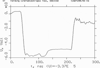
At first, the radii of the inner cylinder, the strip spiral middle cylinder, and the outer cylinder are 5 cm, 20 cm, and 27.5 cm, respectively. Obviously this does not agree with the designed condition of the SSBL for getting an ideal voltage waveform on the matched load, namely r 22 ≠ r 1r 3. The output voltage wave of the field-emission diode is shown in Figure 10.
Then, the radius of the inner cylinder is increased up to 14.5 cm. In this case, the square of radius of spiral middle cylinder is equal to the product of the radius of the inner cylinder, and the radius of the outer cylinder (r 22 ≈ r 1r 3). Figure 11 shows the output voltage wave of the field-emission diode.
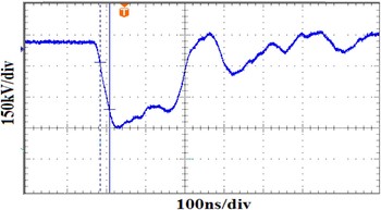
Fig. 11. Output voltage waveform of the field-emission diode at r 22 ≠ r 1r 3.
From the experiment results, it clearly follows that when the geometric dimension of SSBL do not match the condition to obtain an ideal voltage waveform at the match load, there is an obvious step on the flat of the output voltage waveform (Fig. 10), and when the geometric dimension of the SSBL satisfies the equation r 22 = r 1r 3, the output voltage wave is almost a square wave and the fluctuation of the waveform on the flat is very small (Fig. 12). So this contrast experiment confirms the correctness of the theoretical analysis and the simulation. When the square of the radius of the spiral middle cylinder is equal to the product of the radius of the inner cylinder and the radius of the outer cylinder, a good output voltage waveform can be obtained on the match load of SSBL.

Fig. 12. Output voltage waveform of the field-emission diode at r 22 = r 1r 3.
5. CONCLUSIONS
Formulas for calculating inductance, capacitance, transmission time, and characteristic impedance of the SSBL are derived and the Karat code is used for the simulation of the diode voltage to analyze characteristics of SSBL. In addition, some contrast experiments are performed using an electron-beam accelerator based on the SSBL to confirm the theoretical analysis and the simulation. Theoretical analysis, simulation, and experiments lead to the following conclusions: (1) The slowing coefficient is related to the geometrical dimensions of the SSBL, and the distortion of the output voltage wave of the SSBL is caused by the difference of the slowing coefficients of the inner line and the outer line. (2) When the square of the radius of the spiral middle cylinder is equal to the product of the radius of the inner cylinder and the radius of the outer cylinder, that means, the slowing coefficient of the outer line is equal to the slowing coefficient of the inner line, and the characteristic impedance of the outer line equals the characteristic impedance of the inner line, a good output voltage waveform can be obtained on the matched load. (3) The spiral angel is the most important factor to effect the pulse duration of the SSBL, the pulse duration increases with the increase of the spiral angle, but the fluctuation of the output voltage waveform on the flat also increases.
So, in order to get an ideal voltage waveform at the load and to improve the electron beam quality of such an accelerator, the geometric dimension of the SSBL should be designed to match the condition of the ideal voltage waveform as far as possible, namely, r 22 = r 1r 3.
ACKNOWLEDGMENTS
The authors gratefully acknowledge the support from the National Natural Science Foundation of China under Grand No. 10675168. The authors also acknowledge the generous support by J. H Yang and H. W. Yang for their encouragement and valuable suggestion, and they thank L. R. Xu, X. Zhou, Y. Liu, and J. C. Wen for their assistance in the assembly and testing of accelerator.