1 Introduction
Shock interactions with turbulent boundary layers have ubiquitous occurrence in high speed air platforms, and shock-induced boundary layer separation is the dominant cause for several undesirable phenomena like scramjet inlet unstart, premature failure of control surfaces and roll/side-force reversal in ammunitions, among others. Due to their importance, shock wave/boundary layer interactions (SBLI) and shock-induced flow separation have been extensively investigated over the last several decades. The majority of these studies have focused on planar geometries, such as compression ramps (Settles, Vas & Bogdonoff Reference Settles, Vas and Bogdonoff1976; Andreopoulos & Muck Reference Andreopoulos and Muck1987; Vanstone, Musta & Clemens Reference Vanstone, Musta and Clemens2018), sharp fins (Kubota & Strollery Reference Kubota and Strollery1982; Knight et al. Reference Knight, Horstman, Shapey and Bogdonoff1987) and impinging shock interactions (Humble et al. Reference Humble, Elsinga, Scarano and van Oudheusden2009; Piponniau et al. Reference Piponniau, Dussauge, Debieve and Dupont2009; Souverein et al. Reference Souverein, Dupont, Debiève, Dussauge, van Oudheusden and Scarano2010) etc. with canonical turbulent boundary layers. Much of the progress made over the last several decades are reviewed in many articles: Settles & Dodson (Reference Settles and Dodson1994), Dolling (Reference Dolling2001), Clemens & Narayanaswamy (Reference Clemens and Narayanaswamy2014) and Gaitonde (Reference Gaitonde2015).
Among the different geometries studied, SBLI generated by sharp fins has direct relevance to control forces and moments generated in supersonic air vehicles, projectiles and munitions. Almost all previous studies on fin SBLI were made in planar configurations where the fin is placed on a flat plate (Dolling Reference Dolling2001; Knight et al. Reference Knight, Yan, Panaras and Zheltovodov2003; Zheltovodov Reference Zheltovodov2006; Gaitonde Reference Gaitonde2015). In some of the earliest works, Bogdonoff’s group (Settles, Perkins & Bogdonoff Reference Settles, Perkins and Bogdonoff1980; Tan, Tran & Bogdonoff Reference Tan, Tran and Bogdonoff1987; Bogdonoff Reference Bogdonoff1989) made wall pressure measurements to investigate appropriate scaling parameters. They found that the incoming boundary layer displacement thickness, which is used in two-dimensional (2-D) closed separations, is not an appropriate parameter to scale ‘open’ separations: this was the first indication of the possible absence of the relevant length scale for this type of separation. Settles & Lu (Reference Settles and Lu1985) and Settles & Kimmel (Reference Settles and Kimmel1986) examined the pressure fields of the SBLI generated by sharp fins and cones, and showed that the SBLI unit exhibited quasi-conical symmetry, meaning the statistical properties of the unit are relatively constant along radial lines originating from a virtual conical origin (VCO). They also showed that the cone vertex angle (measured with respect to the free-stream direction) resulted in a good agreement in the mean and root-mean-square (r.m.s.) pressure profiles. Subsequent works by Gibson & Dolling (Reference Gibson and Dolling1991) and Schmisseur & Dolling (Reference Schmisseur and Dolling1994) showed that the power spectrum of the wall pressure fluctuations also collapsed along a given cone vertex angle.
Accurate prediction of the onset of shock-induced flow separation onset in sharp-fin SBLI has been of significant interest to the research community. Korkegi (Korkegi Reference Korkegi1973) obtained separation data over several fin- and ramp-induced SBLI, and collated his data with other separation data in the literature spanning a wide range of Mach numbers and shock strength. He showed that the shock strength (quantified by inviscid pressure ratio) that causes separation in 2-D ramp-SBLI has a Mach number dependence. In contrast, separation in the 3-D fin-SBLI occurred when the inviscid pressure jump across the shock exceeded the upstream pressure by 50 % without a Mach number dependence. While several subsequent works showed agreement with Korkegi’s separation criterion, many works also reported a Reynolds number dependence on separation onset. To address some of the dependence of the state of incoming boundary layer on separation, free interaction theory (FIT) argued that the shear forces within the boundary layer subjected to an adverse pressure gradient will help overcome the pressure forces. Using the momentum balance close to the wall, a relation between the wall pressure beneath the separation point and the inflow properties was derived. This relation was further used to determine the shock strength corresponding to separation onset. The free interaction theory was also extended to 3-D planar fin SBLI to predict separation onset and the static pressure beneath the primary separation (Babinsky & Harvey Reference Babinsky and Harvey2011). Several efforts showed that the FIT predictions work quite well at low and moderate Reynolds numbers. Subsequent efforts developed empirical relations and corrections to FIT to predict the separation onset with much better accuracy at high Reynolds numbers and in more complex geometries. Babinsky & Harvey (Reference Babinsky and Harvey2011) have compiled several of these studies and their regimes of application.
Once the flow is separated, further increase in fin shock strength is reported to produce interesting flow fields that correlate with the shock strength. Zheltovodov (Reference Zheltovodov1982) characterized different regimes of separation based on the fin shock strength and Mach number. Using his nomenclature, these regimes are classified as: (I) interaction without boundary layer separation, (II) interaction with boundary layer primary separation (and no secondary separation), (III) flow with secondary separation, (IV) secondary separation attenuation, (V) disappearance of secondary separation and (VI) reappearance of secondary separation. For a given Mach number, increasing the fin angle transitions the SBLI regimes from I through VI. Thus, post separation, further increase in the shock strength causes the generation of additional set of separation and reattachment, called secondary separation (regime III). An illustration of the flow field is shown in figure 1. This secondary separation is characterized by a secondary separation vortex that is generated by the outer flow that is recirculated from the leading edge of the primary separation vortex (close to the fin root). However, with increasing shock strength, the velocity of recirculated flow from the leading edge increases into the turbulent regime, which is more resistant to separation (Babinsky & Harvey Reference Babinsky and Harvey2011). This was suggested to cause the suppression and disappearance of the secondary separation (regimes IV and V), which was corroborated by Zheltovodov, Maksimov & Shilein (Reference Zheltovodov, Maksimov and Shilein1987). Subsequently, the investigation done by Baldwin et al. (Reference Baldwin, Arora, Kumar and Alvi2016) on the effect of Reynolds number on the sharp-fin SBLI resulted in flow patterns largely consistent with the regimes demarcated by Zheltovodov. The only exception is the case for a free-stream Mach number of 3 and a fin deflection angle of
![]() $22^{\circ }$
where Baldwin et al. (Reference Baldwin, Arora, Kumar and Alvi2016) noticed the presence of secondary separation, despite this test case falling within regime V. Interestingly, the experimental results modelled by Horstman deviate in the same way for a free-stream Mach number of 3.95 and a
$22^{\circ }$
where Baldwin et al. (Reference Baldwin, Arora, Kumar and Alvi2016) noticed the presence of secondary separation, despite this test case falling within regime V. Interestingly, the experimental results modelled by Horstman deviate in the same way for a free-stream Mach number of 3.95 and a
![]() $20^{\circ }$
sharp fin (Horstman Reference Horstman1989). With further increase in shock strength, recirculating flow velocity exceeds sonic conditions and a normal shock forms at the recirculating flow that causes the re-emergence of the secondary separation (regime VI).
$20^{\circ }$
sharp fin (Horstman Reference Horstman1989). With further increase in shock strength, recirculating flow velocity exceeds sonic conditions and a normal shock forms at the recirculating flow that causes the re-emergence of the secondary separation (regime VI).

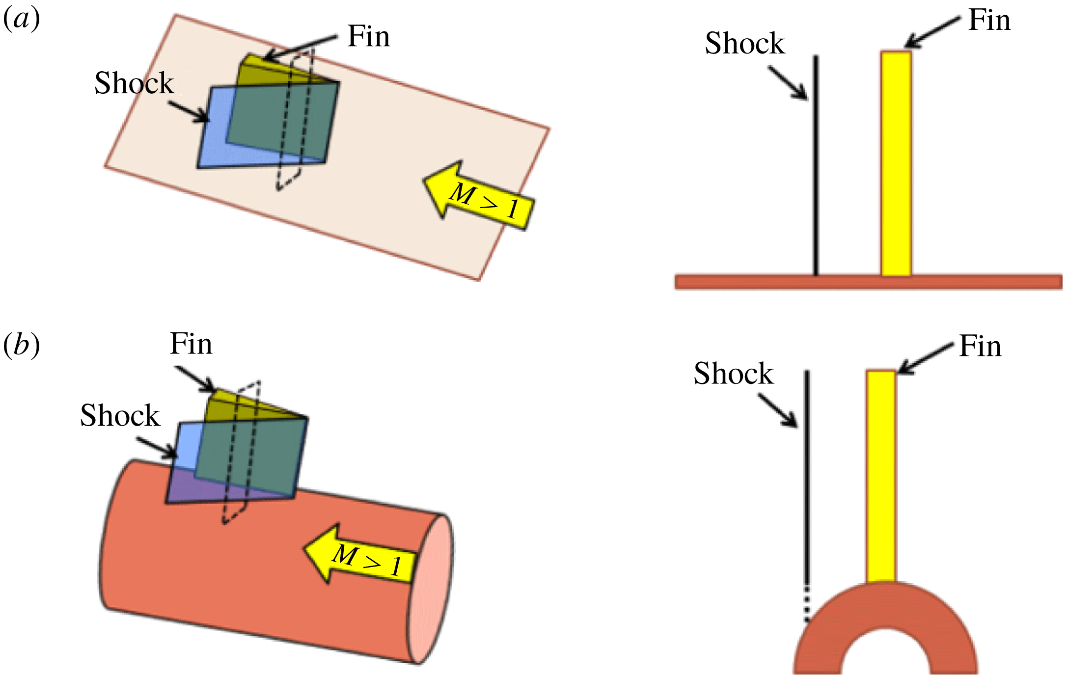
Figure 1. Sketch of
![]() $\unicode[STIX]{x1D706}$
-shock structure: (a) streamwise and (b) top views, based on Alvi & Settles (Reference Alvi and Settles1992).
$\unicode[STIX]{x1D706}$
-shock structure: (a) streamwise and (b) top views, based on Alvi & Settles (Reference Alvi and Settles1992).
Alvi & Settles (Reference Alvi and Settles1992) provided excellent qualitative visualization of the off-body flow/ shock structures associated with open separation generated in regime III using conical shadowgraphy and planar laser scattering. A schematic of the separation unit based on their findings is illustrated in figure 1. It can be observed from figure 1 that the inviscid shock bifurcates into a
![]() $\unicode[STIX]{x1D706}$
-shape when it interacts with the boundary layer. The boundary layer separates behind the upstream stem of the
$\unicode[STIX]{x1D706}$
-shape when it interacts with the boundary layer. The boundary layer separates behind the upstream stem of the
![]() $\unicode[STIX]{x1D706}$
-shock to form a primary separation vortex and subsequently reattaches behind the downstream stem of the
$\unicode[STIX]{x1D706}$
-shock to form a primary separation vortex and subsequently reattaches behind the downstream stem of the
![]() $\unicode[STIX]{x1D706}$
-shock, and the size of this open separation scales with the shock strength (i.e. fin angle and incoming Mach number). Furthermore, the primary streamwise vortex extends from the line of primary separation S1 to primary reattachment R1. A slip stream emanating from the triple point of the
$\unicode[STIX]{x1D706}$
-shock, and the size of this open separation scales with the shock strength (i.e. fin angle and incoming Mach number). Furthermore, the primary streamwise vortex extends from the line of primary separation S1 to primary reattachment R1. A slip stream emanating from the triple point of the
![]() $\unicode[STIX]{x1D706}$
-shock impinges upon the plate near the root of the fin that causes a sharp rise in the unsteady pressure loading near this impingement location. A sufficiently high velocity reverse flow was also created underneath the primary separation vortex, which results in a region of secondary separation, bounded by the separation and reattachment points S2 and R2, respectively. The experimental findings were also corroborated by Reynolds-averaged Navier–Stokes (RANS) simulations and large-eddy simulations (LES) employing different turbulence models (Knight et al.
Reference Knight, Horstman, Shapey and Bogdonoff1987) and using more advanced measurement approaches (Arora, Alvi & Ali Reference Arora, Alvi and Ali2016).
$\unicode[STIX]{x1D706}$
-shock impinges upon the plate near the root of the fin that causes a sharp rise in the unsteady pressure loading near this impingement location. A sufficiently high velocity reverse flow was also created underneath the primary separation vortex, which results in a region of secondary separation, bounded by the separation and reattachment points S2 and R2, respectively. The experimental findings were also corroborated by Reynolds-averaged Navier–Stokes (RANS) simulations and large-eddy simulations (LES) employing different turbulence models (Knight et al.
Reference Knight, Horstman, Shapey and Bogdonoff1987) and using more advanced measurement approaches (Arora, Alvi & Ali Reference Arora, Alvi and Ali2016).
Significant computational efforts were also undertaken by several researchers to predict the complex flow structure and surface pressure patterns under various conditions. These include the RANS simulations by several different groups, as reviewed by Thivet (Reference Thivet2002), Knight et al. (Reference Knight, Yan, Panaras and Zheltovodov2003) and more recently by Gaitonde (Reference Gaitonde2015) and LES simulations of Loginov, Adams & Zheltovodov (Reference Loginov, Adams and Zheltovodov2006), Touber & Sandham (Reference Touber and Sandham2009) and Fang et al. (Reference Fang, Lu, Yao and Zheltovodov2017). While most turbulence models used for the RANS simulations provided a reasonably accurate prediction of the onset of primary separation, they showed severe discrepancy with experiments for predicting the onset of secondary separation (regime III). Remarkably, none of the standard turbulence models could predict the secondary separation that were experimentally observed. A weakly nonlinear extension of the
![]() $k-\unicode[STIX]{x1D714}$
model (Wilcox Reference Wilcox1988) due to Durbin (Reference Durbin1996) predicted the secondary separation with significantly better fidelity compared to the standard models (Zheltovodov Reference Zheltovodov2006). Upon closer investigation, it was shown that the success of the revised model in predicting the secondary separation onset coincided with a smaller turbulence kinetic energy within the primary separation vortex and the shear layer above the vortex. Thus, the secondary separation is determined by the turbulence features of the primary separation vortex, and, perhaps, the entrainment characteristics of the shear layer.
$k-\unicode[STIX]{x1D714}$
model (Wilcox Reference Wilcox1988) due to Durbin (Reference Durbin1996) predicted the secondary separation with significantly better fidelity compared to the standard models (Zheltovodov Reference Zheltovodov2006). Upon closer investigation, it was shown that the success of the revised model in predicting the secondary separation onset coincided with a smaller turbulence kinetic energy within the primary separation vortex and the shear layer above the vortex. Thus, the secondary separation is determined by the turbulence features of the primary separation vortex, and, perhaps, the entrainment characteristics of the shear layer.
Compared to planar fin SBLI, only a few studies exist for axisymmetric configurations. Axisymmetric fin SBLI studies like those of Blair Jr, Allen & Hernandez (Reference Blair, Allen and Hernandez1983) focused on determining the integrated forces on missile-like models (Sahu Reference Sahu1990; Fresconi, Celmins & Fairfax Reference Fresconi, Celmins and Fairfax2011; Bhagwandin & Sahu Reference Bhagwandin and Sahu2014; Silton & Fresconi Reference Silton and Fresconi2015). The phenomena of pitch and roll reversals were reported in these studies when the fin angles exceed stall angles, wherein further increases in fin angles result in diminished forces and moments. Most subsequent efforts focused on canard and tail fin interactions to predict and control the pitch and roll reversal phenomena (e.g. DeSpirito, Vaughn Jr & Washington Reference DeSpirito, Vaughn and Washington2002; Sahu Reference Sahu2017) without emphasizing the shock-induced flow separation. The works of Hooseria and Skews (Hooseria & Skews Reference Hooseria and Skews2015, Reference Hooseria and Skews2017) have provided deeper insight into 3-D diffraction of shock waves on curved surfaces when two slender bodies are placed in close proximity in supersonic flow. These works show the retention of primary and secondary boundary layer separation on the curved surface, suggesting the planar regimes set forth by Zheltovodov may be retained for curved geometries. Bhagwandin (Reference Bhagwandin2015) performed the only available investigations into the fundamental features of SBLI generated by an incident oblique shock on a cylindrical surface. The author showed a complex separated flow field between the locations where the shock wave made a direct incidence on the cylindrical surface versus the circumferential locations where the shock wave made a grazing incidence like a fin shock. While Bhagwandin’s and Hooseria and Skews’ studies show the rich flow physics associated with an impinging shock on a cylinder surface, it is not directly extendable to the SBLI generated by a sharp fin placed on the cylindrical surface as the impinging inviscid shock structure is substantially different from that generated by a fin mounted on a cylinder surface.
Recently, the current authors made some of the first direct investigations into the SBLI generated by a sharp fin placed on the cylindrical surface (Pickles, Mettu, Subbareddy & Narayanaswamy Reference Pickles, Mettu, Subbareddy and Narayanaswamy2017; Pickles et al. Reference Pickles, Mettu, Subbareddy and Narayanaswamy2018). The current paper seeks to quantitatively and qualitatively describe the underlying physics of shock wave/turbulent boundary layers interactions generated by a sharp fin mounted on a cylindrical surface, building upon the authors previous investigations (Pickles et al. Reference Pickles, Mettu, Subbareddy and Narayanaswamy2017). Specifically, the authors investigate: (i) the global separated flow regimes at different fin/Mach number combinations and their correspondence to planar fin SBLI; (ii) the off-body flow features that correspond to surface streakline visualizations; (iii) mean surface pressure fields of the fin SBLI on the cylindrical surface; and (iv) mechanisms that drive the mean separation features of fin-on-cylinder SBLI.
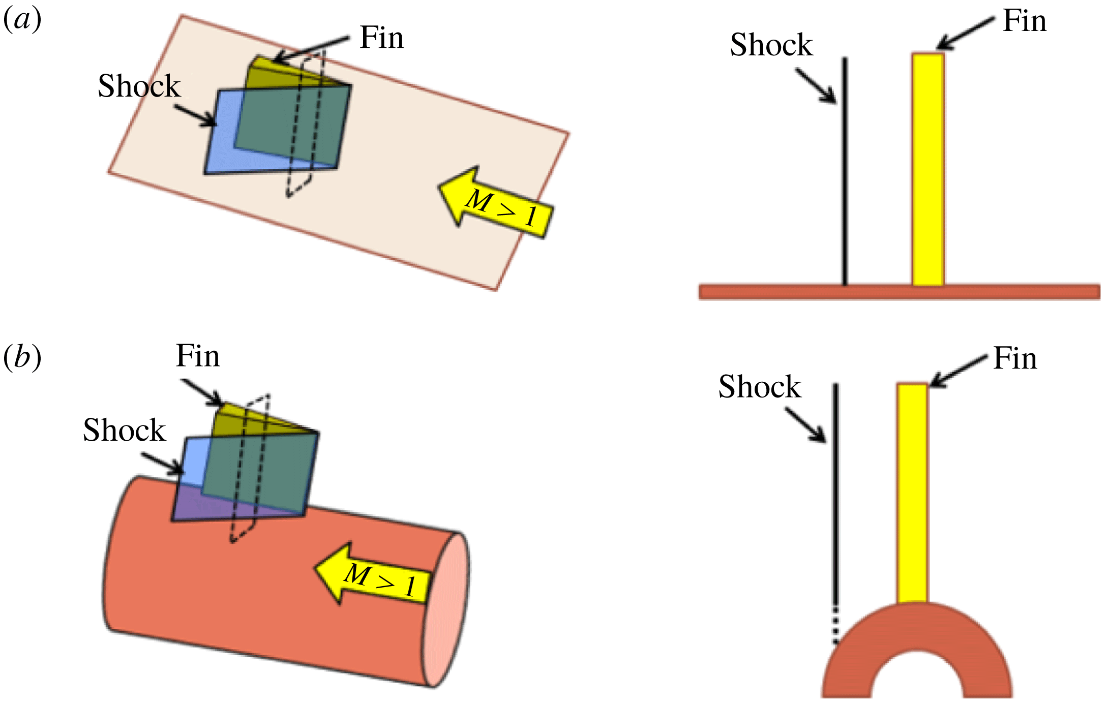
Figure 2. Illustration of fundamental modifications to the inviscid shock structure generated in a fin-on-cylinder configuration.
2 Problem context
Before discussing the details of the experiments, it is important to illustrate the uniqueness of the flow configuration studied to show that fin SBLI over a cylindrical surface (or any curved surface) is not a simple extension of planar fin SBLI. Figure 2 considers an inviscid supersonic flow over an infinitely tall fin placed on a flat plate (figure 2 a) and on a cylindrical surface (figure 2 b). A cross-section of the shock wave at a downstream distance for the two cases (shown as a dashed rectangle) is compared for the two cases. It can be observed that for the planar case, the inviscid shock wave retains its strength and shape across the fin height all the way to the plate surface. In contrast, for the case of fin mounted on a cylindrical surface, the inviscid shock of a constant strength will extend across the fin height; however, the shock strength cannot be supported in the region close to the cylindrical surface (shown as dashed line) as there is no compression surface. This modifies the inviscid shock structure and features in the region close to the cylindrical surface. The details of the inviscid shock system and the resulting inviscid pressure fields are discussed in greater depth subsequently. For now, it is important to note that even the inviscid shock system generated by the fin mounted on a cylindrical surface is quite different from the planar case. The incoming boundary layer reacts to the adverse pressure gradient caused by the modified inviscid shock, resulting in interesting outcomes to the SBLI flow field that are different from the planar fin SBLI.
The 3-D relief offered by the cylindrical surface can also influence the shock structure and the SBLI unit. The 3-D relief of the cylindrical surface described in this paper denotes the additional room along the azimuthal direction offered to the flow due to the curvature of the cylinder surface. This additional room for flow migration also results in interesting outcomes on the mean separation features and the shock structure of the fin-on-cylinder SBLI unit. The mean features of the fin-on-cylinder SBLI unit and the resulting separated flow form the subject of this paper.
3 Experimental and computational set-up
3.1 Experimental approach
All experiments were performed in the supersonic wind tunnel facility at North Carolina State University at a Mach number of 2.5. This is a blowdown tunnel and has a constant-area test section measuring
![]() $150~\text{mm}\times 150~\text{mm}\times 650~\text{mm}$
. Each run lasted 6 s with a constant stagnation pressure and temperature of 450 kPa and
$150~\text{mm}\times 150~\text{mm}\times 650~\text{mm}$
. Each run lasted 6 s with a constant stagnation pressure and temperature of 450 kPa and
![]() $300\,\text{K}$
, respectively. These conditions resulted in a free-stream unit Reynolds number of approximately
$300\,\text{K}$
, respectively. These conditions resulted in a free-stream unit Reynolds number of approximately
![]() $5.3\times 10^{7}~\text{m}^{-1}$
and a free-stream temperature of
$5.3\times 10^{7}~\text{m}^{-1}$
and a free-stream temperature of
![]() $130\,\text{K}$
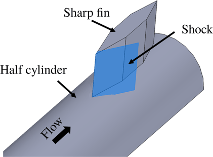
. A half-cylinder model, 430 mm long, was placed facing the free stream at nominally zero yaw and pitch angle with respect to the incoming flow, as shown in figure 3. The leading edge of the model was machined to a sharp edge with a linear internal chamfer of
$130\,\text{K}$
. A half-cylinder model, 430 mm long, was placed facing the free stream at nominally zero yaw and pitch angle with respect to the incoming flow, as shown in figure 3. The leading edge of the model was machined to a sharp edge with a linear internal chamfer of
![]() $9.5^{\circ }$
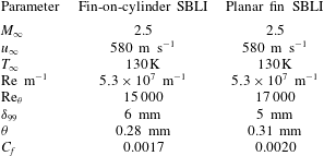
. Its mounting struts recessed the entire section away from the wind tunnel wall boundary layer. A boundary layer developed over the cylindrical surface that naturally transitioned to a fully developed equilibrium turbulent boundary layer, as verified with a van Driest II transform of the boundary layer velocity profile (Hopkins Reference Hopkins1972). A sharp fin was mounted on the cylinder surface at a downstream distance of 340 mm; the boundary layer thickness measured 65 mm upstream of the fin leading edge was 6 mm. A summary of the incoming boundary layer parameters is in table 1.
$9.5^{\circ }$
. Its mounting struts recessed the entire section away from the wind tunnel wall boundary layer. A boundary layer developed over the cylindrical surface that naturally transitioned to a fully developed equilibrium turbulent boundary layer, as verified with a van Driest II transform of the boundary layer velocity profile (Hopkins Reference Hopkins1972). A sharp fin was mounted on the cylinder surface at a downstream distance of 340 mm; the boundary layer thickness measured 65 mm upstream of the fin leading edge was 6 mm. A summary of the incoming boundary layer parameters is in table 1.
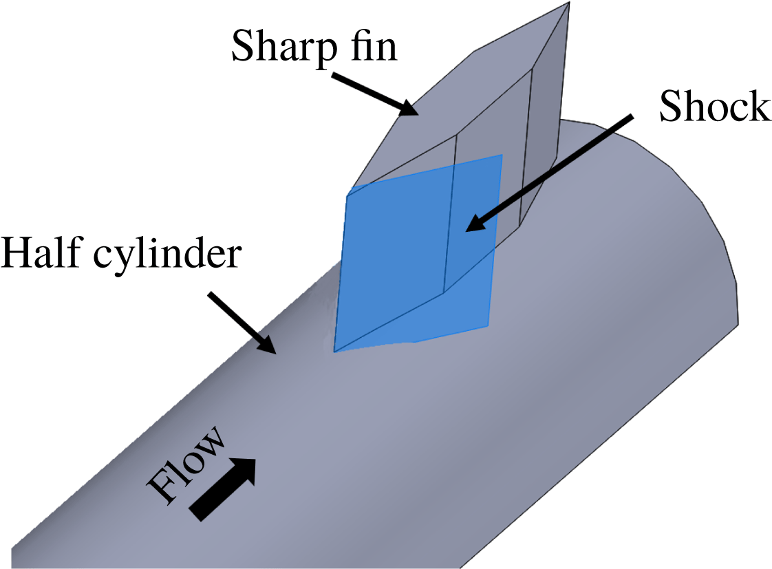
Figure 3. Schematic of the test article used for the studies.
For most experiments presented in this work, the fins were 25 mm in height, which was approximately a factor of four taller than the incoming boundary layer thickness. However, isolated studies were made using another 50 mm tall fin for certain fin angles to explore the effect of fin height on the SBLI. Two half-cylinder models with outer diameter of 50 mm and 76 mm were employed for this study, and fin half-angles of
![]() $\unicode[STIX]{x1D6FC}=5^{\circ }$
,
$\unicode[STIX]{x1D6FC}=5^{\circ }$
,
![]() $10^{\circ }$
,
$10^{\circ }$
,
![]() $12^{\circ }$
,
$12^{\circ }$
,
![]() $14^{\circ }$
and
$14^{\circ }$
and
![]() $20^{\circ }$
were used. The maximum thickness of each fin was approximately 9.5 mm, which was a factor of 2.7 to 4 smaller than the different half-cylinder model radius. The fins made a line contact with the cylinder surface, and the maximum gap between the fin root and the cylinder surface was less than 1 mm. The swept shock that emanated from the fin interacted with the incoming boundary layer to result in the SBLI unit, as shown in figure 3. Two free-stream Mach numbers of 2.5 and 3 were employed for the 76 mm diameter case for all fin angles.
$20^{\circ }$
were used. The maximum thickness of each fin was approximately 9.5 mm, which was a factor of 2.7 to 4 smaller than the different half-cylinder model radius. The fins made a line contact with the cylinder surface, and the maximum gap between the fin root and the cylinder surface was less than 1 mm. The swept shock that emanated from the fin interacted with the incoming boundary layer to result in the SBLI unit, as shown in figure 3. Two free-stream Mach numbers of 2.5 and 3 were employed for the 76 mm diameter case for all fin angles.
Table 1. Incoming flow and boundary layer characteristics.
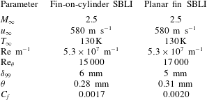
Complementary investigations were also performed in a planar fin SBLI configuration with a selected fin angle to learn how the mean features of fin-on-cylinder SBLI contrast with those of a canonical planar fin SBLI. The planar fin SBLI was generated by a
![]() $20^{\circ }$
sharp fin that was mounted to a 370 mm long flat plate in Mach 2.5 flow. A boundary layer developed over the plate surface and transitioned naturally to fully developed turbulent boundary layer. The fin was mounted such that its leading edge was located approximately 270 mm downstream of the plate leading edge, and the plate’s mounting struts recessed the unit away from the wind tunnel wall boundary layer. A summary of the incoming boundary layer characteristics is shown in table 1. Comparison of the entries in table 1 shows that the boundary layer parameters are quite similar between the fin-on-cylinder and planar fin SBLI geometries, allowing for direct comparison between the two configurations.
$20^{\circ }$
sharp fin that was mounted to a 370 mm long flat plate in Mach 2.5 flow. A boundary layer developed over the plate surface and transitioned naturally to fully developed turbulent boundary layer. The fin was mounted such that its leading edge was located approximately 270 mm downstream of the plate leading edge, and the plate’s mounting struts recessed the unit away from the wind tunnel wall boundary layer. A summary of the incoming boundary layer characteristics is shown in table 1. Comparison of the entries in table 1 shows that the boundary layer parameters are quite similar between the fin-on-cylinder and planar fin SBLI geometries, allowing for direct comparison between the two configurations.
3.2 Surface streakline visualization
Surface streakline visualizations (SSV) of the separated flow caused by the fin SBLI were performed for all experimental configurations. To perform the visualization, the test model was painted with a mixture of UV-fluorescent pigment and mineral oil before the experimental run. As the wind tunnel stream flowed over the model during the test run, the dye mixture was driven by the flow shear to result in streakline patterns that provided a qualitative picture of the local shear stress. Furthermore, the dye mixture accumulated at the regions of low shear stress because of the lack of a driving shear force, allowing for the identification of separation and reattachment loci. While the streaklines appear to converge at the (primary and secondary) separation loci, a distinct line from which the streaklines diverge identifies the reattachment loci. In this manner, a qualitative view of the separated flow topology can be obtained. The convergence and divergence of the streaklines were determined by obtaining a movie of the dye flow during the experimental run at 60 fps. The visualization quality was enhanced by illuminating the measurement region using an 18 W UV lamp, which yielded stark fluorescence signals from the dye that contrasted well with the black cylinder surface.
3.3 Planar laser scattering
Planar laser scattering (PLS) was performed for the
![]() $20^{\circ }$
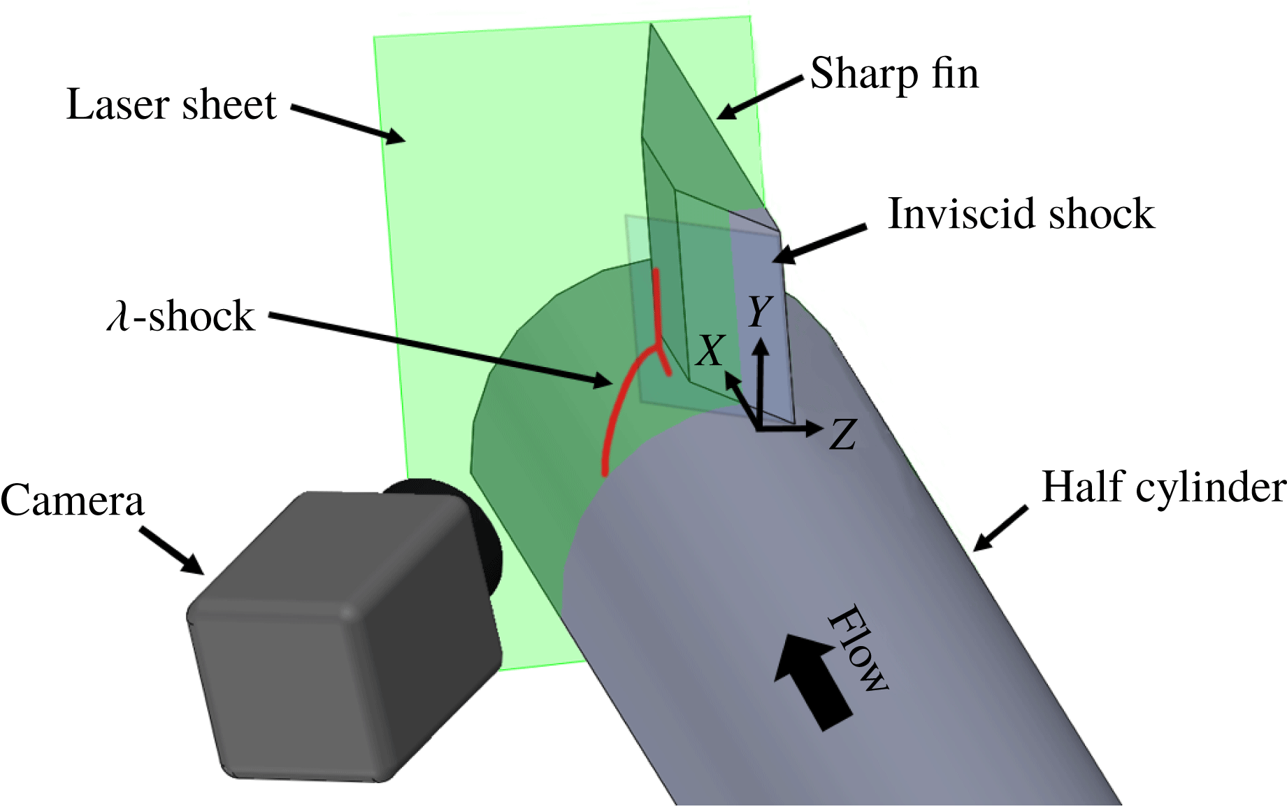
half-angle fin mounted on a 50 mm diameter cylinder at Mach 2.5 to unravel the streamwise evolution of the off-body flow and shock features in the SBLI. A schematic of this set-up is shown in figure 4. Water vapour was introduced into the wind tunnel stream at the storage tanks by controlling the dew point of the dryer unit. The water vapour condensed to a droplet fog in the regions of low temperature such as the wind tunnel free stream, across the inviscid and separation shock etc., which provides large scattering signals to help visualize these features. Regions of higher density (such as downstream of a shock) result in brighter intensity due to larger seeding density, whereas the viscous regions such as the lower part of the incoming boundary layer and separated flow appear dark due to their elevated temperatures that causes the fog to evaporate. The water fog was illuminated using Nd-YAG lasers operating at 10 Hz and an output energy of approximately 80 mJ per pulse. The resulting scattering signals were imaged using an interline CCD camera (PCO Tech, Model: Pixelfly) fitted with a 532 nm filter and 105 mm f/4.0 lens. The measurement region spanned
$20^{\circ }$
half-angle fin mounted on a 50 mm diameter cylinder at Mach 2.5 to unravel the streamwise evolution of the off-body flow and shock features in the SBLI. A schematic of this set-up is shown in figure 4. Water vapour was introduced into the wind tunnel stream at the storage tanks by controlling the dew point of the dryer unit. The water vapour condensed to a droplet fog in the regions of low temperature such as the wind tunnel free stream, across the inviscid and separation shock etc., which provides large scattering signals to help visualize these features. Regions of higher density (such as downstream of a shock) result in brighter intensity due to larger seeding density, whereas the viscous regions such as the lower part of the incoming boundary layer and separated flow appear dark due to their elevated temperatures that causes the fog to evaporate. The water fog was illuminated using Nd-YAG lasers operating at 10 Hz and an output energy of approximately 80 mJ per pulse. The resulting scattering signals were imaged using an interline CCD camera (PCO Tech, Model: Pixelfly) fitted with a 532 nm filter and 105 mm f/4.0 lens. The measurement region spanned
![]() $50~\text{mm}\times 50~\text{mm}$
with a resulting pixel resolution of
$50~\text{mm}\times 50~\text{mm}$
with a resulting pixel resolution of
![]() $77~\unicode[STIX]{x03BC}\text{m}~\text{pxl}^{-1}$
.
$77~\unicode[STIX]{x03BC}\text{m}~\text{pxl}^{-1}$
.

Figure 4. Schematic of the PLS set-up used for the experiments.
The background scattering was first subtracted from the raw PLS images, and subsequently laser sheet variations were corrected for by normalizing each row of the images with the corresponding free-stream signals. The injection of the water vapour in the storage tanks resulted in a homogeneous seeding distribution within the test section, which enabled the determination of quantitative gas densities across the SBLI from the free-stream-normalized PLS images. Many of the details about this technique and the figures of merit like measurement uncertainty are described elsewhere (Pickles et al. Reference Pickles, Mettu, Subbareddy and Narayanaswamy2018), with a similar technique using nanoparticles having been performed by Tian et al. (Reference Tian, Yi, Zhao, He and Cheng2009). Briefly, a mapping was generated between the free-stream-normalized PLS ratio and the corresponding gas density ratio by obtaining the PLS ratio across several known shock strengths generated by 2-D wedges. This mapping accounts for the physical process that the ice/fog particulates undergo across the shock wave, which causes changes in the particulate size distribution and consequently impacts the PLS signals. Our measurements provided mean gas densities in fin-on-cylinder SBLI within 3 % uncertainty across the measurement domain limited to regions away from viscous dominated regions. Further statistical information such as the ensemble average and r.m.s. of the normalized PLS images were computed using 120 PLS fields obtained across two different experimental runs.
3.4 Mean pressure imaging
Mean wall pressure over a region spanning the SBLI was measured to quantify and correlate the pressure field to streakline and off-body shock features. For the present study, a specific case of SBLI generated by a
![]() $20^{\circ }$
fin placed over a 50 mm cylinder in Mach 2.5 flow was employed. A high frequency response pressure sensitive paint (ISSI Inc.) was used for pressure imaging. The said paint was specified to be sensitive down to 5 Pa with a response time of
$20^{\circ }$
fin placed over a 50 mm cylinder in Mach 2.5 flow was employed. A high frequency response pressure sensitive paint (ISSI Inc.) was used for pressure imaging. The said paint was specified to be sensitive down to 5 Pa with a response time of
![]() ${<}1~\text{ms}$
. The paint was illuminated using a water-cooled LED lamp with an output power of 20 W, and the fluorescence of the paint was captured at 60 Hz using a 12-bit CMOS camera (Photron, Model: FASTCAM SA-X2) fitted with a 600 nm longpass optical filter. The fluorescence signals were then mapped to pressure data using an in-house calibration performed with a vacuum cell. Approximately 200 images were averaged that spanned 6 seconds of steady operation to generate the mean pressure field that was used in the current work. The resulting spatial resolution of the pressure field was
${<}1~\text{ms}$
. The paint was illuminated using a water-cooled LED lamp with an output power of 20 W, and the fluorescence of the paint was captured at 60 Hz using a 12-bit CMOS camera (Photron, Model: FASTCAM SA-X2) fitted with a 600 nm longpass optical filter. The fluorescence signals were then mapped to pressure data using an in-house calibration performed with a vacuum cell. Approximately 200 images were averaged that spanned 6 seconds of steady operation to generate the mean pressure field that was used in the current work. The resulting spatial resolution of the pressure field was
![]() $250~\unicode[STIX]{x03BC}\text{m}~\text{pxl}^{-1}$
.
$250~\unicode[STIX]{x03BC}\text{m}~\text{pxl}^{-1}$
.
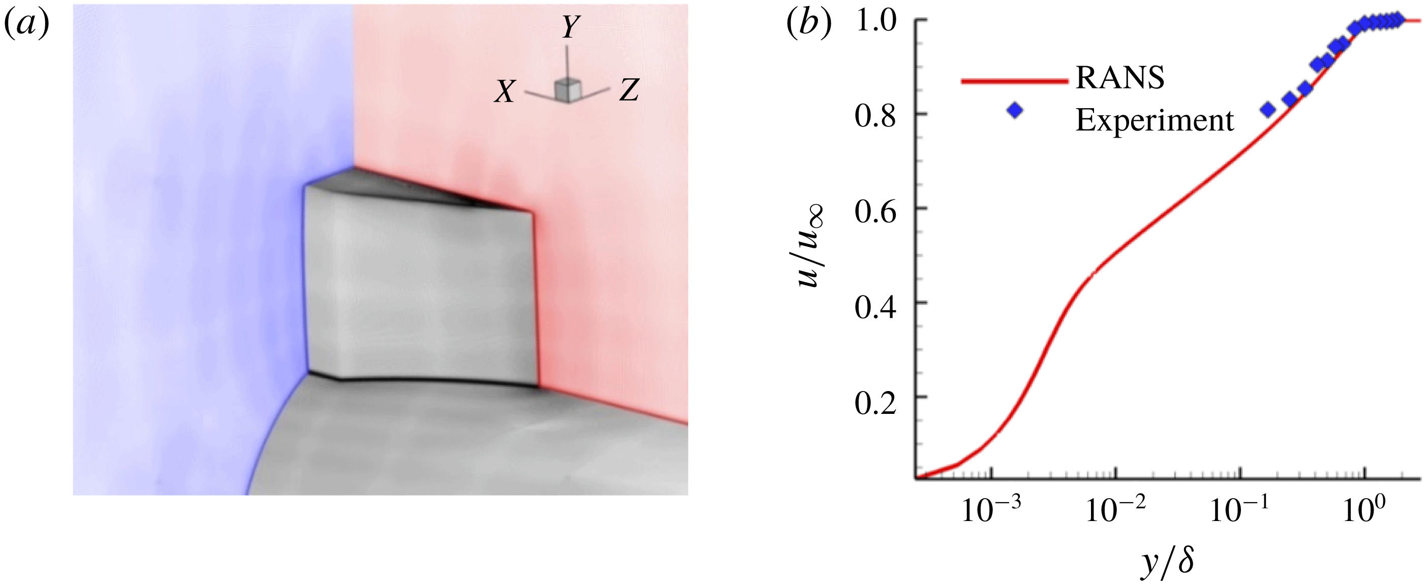
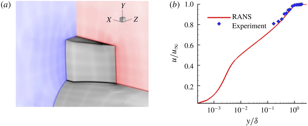
Figure 5. (a) Illustration of the grid generated for the Euler and RANS simulations used in this study. (b) Boundary layer profile comparison between the RANS and the experiment.
3.5 Computational approach
Complementary computations were performed to provide a theoretical understanding of the influence of the cylindrical surface on the inviscid shock structure (using Euler and RANS simulations) and to analyse the influence of wind tunnel boundary layer on the separated flow topology (using RANS). We used an unstructured finite-volume Navier–Stokes solver (US3D) that was developed at the University of Minnesota (Nompelis, Drayna & Candler Reference Nompelis, Drayna and Candler2004, Reference Nompelis, Drayna and Candler2005; Subbareddy & Candler Reference Subbareddy and Candler2009). Fluxes were computed using the upwind, modified Steger–Warming flux due to MacCormack & Candler (Reference MacCormack and Candler1989). Viscous fluxes were formed using a central, second-order accurate method. For time integration, we used the implicit data parallel line relaxation (DPLR) scheme (Wright, Candler & Bose Reference Wright, Candler and Bose1998). Turbulence closure was obtained via the one-equation Spalart–Allmaras eddy-viscosity model (Spalart & Allmaras Reference Spalart and Allmaras1992) in its RANS form.
The RANS simulation was performed on a truncated version of the experimental model, as shown in figure 5. A highly refined grid (around 88 million cells) was used for this in order to capture the shocks cleanly. The simulation was done for the fin with a half-angle of
![]() $20^{\circ }$
on a cylinder with a diameter of approximately 50 mm. The geometry was cut in half along the
$20^{\circ }$
on a cylinder with a diameter of approximately 50 mm. The geometry was cut in half along the
![]() $XY$
symmetry plane and the inflow plane was placed 65 mm upstream of the fin leading edge. This distance of approximately 10.5
$XY$
symmetry plane and the inflow plane was placed 65 mm upstream of the fin leading edge. This distance of approximately 10.5
![]() $\unicode[STIX]{x1D6FF}_{0}$
, where
$\unicode[STIX]{x1D6FF}_{0}$
, where
![]() $\unicode[STIX]{x1D6FF}_{0}$
, the inflow plane boundary layer thickness, was chosen to allow enough distance for the boundary layer to develop before it interacts with the fin. The grid for this fin–cylinder geometry was generated using GridPro, a commercial grid generation software for creating multi-block hexahedral element grids. The domain had dimensions of
$\unicode[STIX]{x1D6FF}_{0}$
, the inflow plane boundary layer thickness, was chosen to allow enough distance for the boundary layer to develop before it interacts with the fin. The grid for this fin–cylinder geometry was generated using GridPro, a commercial grid generation software for creating multi-block hexahedral element grids. The domain had dimensions of
![]() $150~\text{mm}\times 76~\text{mm}\times 150~\text{mm}$
$150~\text{mm}\times 76~\text{mm}\times 150~\text{mm}$
![]() $(L\times W\times H)$
to match those of the wind tunnel’s test section and the experimental model. Clustering and nesting of the cells near the cylinder and fin surfaces on the grid was performed using GridPro with a stretch ratio of 1.1 to resolve the boundary layer, and the first wall spacing was set to ensure a
$(L\times W\times H)$
to match those of the wind tunnel’s test section and the experimental model. Clustering and nesting of the cells near the cylinder and fin surfaces on the grid was performed using GridPro with a stretch ratio of 1.1 to resolve the boundary layer, and the first wall spacing was set to ensure a
![]() $y^{+}$
of less than unity.
$y^{+}$
of less than unity.
The steady RANS inflow conditions were generated using a separate 2-D axisymmetric grid. The boundary layer data extracted from the RANS axisymmetric grid simulation are compared with the experimental boundary layer data acquired with Pitot probe measurements in figure 5(b). A free-stream Mach number of 2.5 was prescribed and the boundary layer thickness measured at the inflow plane was approximately 6 mm, consistent with the experimental findings. Isothermal wall boundary conditions were prescribed for the cylinder and fin surfaces with the wall temperature set to
![]() $300\,\text{K}$
. The similarity of the off-body simulated results presented herein and those described in Pickles et al. (Reference Pickles, Mettu, Subbareddy and Narayanaswamy2018) provide confidence in the application of RANS for the scope of this investigation.
$300\,\text{K}$
. The similarity of the off-body simulated results presented herein and those described in Pickles et al. (Reference Pickles, Mettu, Subbareddy and Narayanaswamy2018) provide confidence in the application of RANS for the scope of this investigation.
4 Results
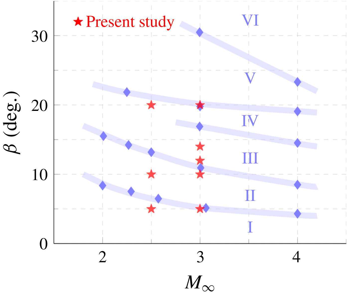
The first part of this study investigates how the global separated flow features change due to the 3-D relief offered by the cylindrical surface. Specifically, we seek to answer: (i) if a fin shock of given inviscid shock strength retains the same separation and reattachment entities when placed on a cylindrical surface versus a flat plate; and (ii) if the separation and reattachment loci evolve in the same (or different) manner along a cylindrical surface versus a flat plate. To answer these questions, surface streakline visualizations of the current fin SBLI over the cylindrical surface spanning different configurations were compared to the planar fin SBLI streaklines of Zheltovodov (Reference Zheltovodov1982) to identify the correspondence between the different separation regimes between fin-on-cylinder SBLI and planar fin SBLI. Figure 6 shows the regimes predicted in Zheltovodov’s original work for planar fin SBLI and the various Mach number/fin angle combinations used in the present study (as symbols). As shown in figure 6, the configurations of this investigation span regimes I–IV. The possible effects of variations in cylinder diameter changes were not considered while plotting this figure.
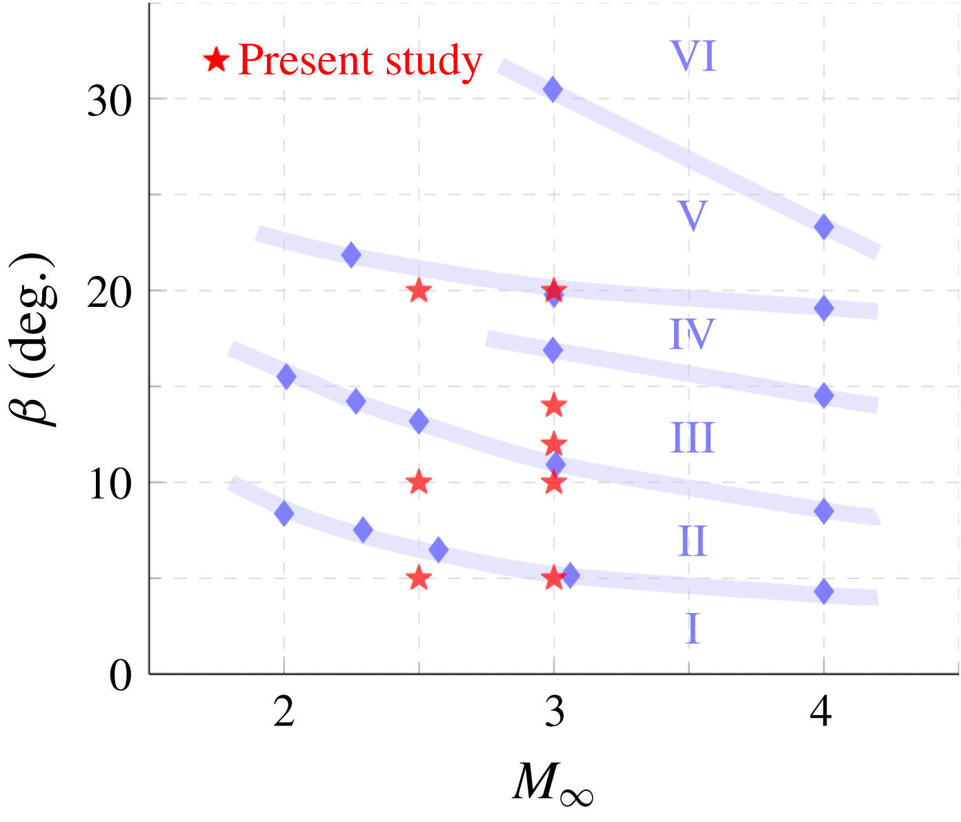
Figure 6. Regime map of primary and secondary separation of planar fin SBLI based on Zheltovodov (Reference Zheltovodov1982) and the projected regimes of the different fin-on-cylinder SBLI configurations used in the current work.
4.1 Identification of flow regimes
The mean surface streaklines from SSV with different fin angles, cylinder diameters and Mach numbers were analysed to answer if the flow field with fin-on-cylinder SBLI does correspond to the planar SBLI regimes shown in figure 6. SSV fields shown in figure 7 encompass fin half-angles
![]() $\unicode[STIX]{x1D6FC}=5^{\circ }$
,
$\unicode[STIX]{x1D6FC}=5^{\circ }$
,
![]() $10^{\circ }$
,
$10^{\circ }$
,
![]() $12^{\circ }$
,
$12^{\circ }$
,
![]() $14^{\circ }$
and
$14^{\circ }$
and
![]() $20^{\circ }$
, cylinder diameters 50 mm and 76 mm and free-stream Mach numbers of 2.5 and 3. All the SSV images are plotted with respect to the cylinder azimuth (
$20^{\circ }$
, cylinder diameters 50 mm and 76 mm and free-stream Mach numbers of 2.5 and 3. All the SSV images are plotted with respect to the cylinder azimuth (
![]() $\unicode[STIX]{x1D703}$
) along the
$\unicode[STIX]{x1D703}$
) along the
![]() $y$
-axis; the
$y$
-axis; the
![]() $x$
-axis corresponds to the streamwise distance. The origin was set at fin leading edge on the cylinder surface and the flow is from right to left (see figure 4).
$x$
-axis corresponds to the streamwise distance. The origin was set at fin leading edge on the cylinder surface and the flow is from right to left (see figure 4).
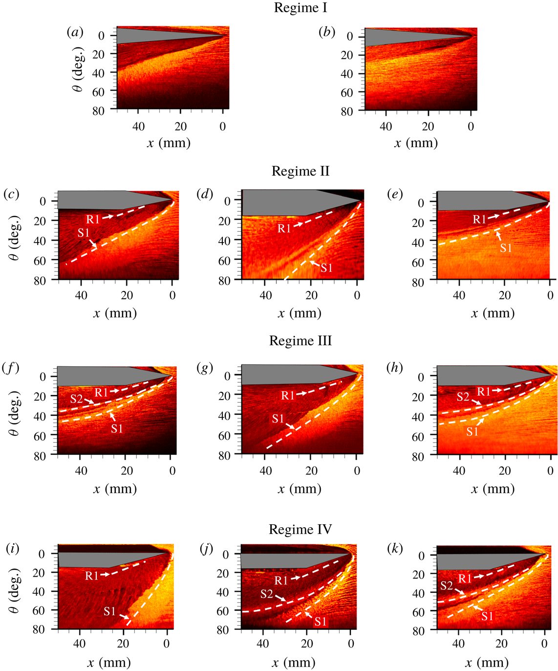
First, the fin SBLI predicted to lie in regime I of Zheltovodov is studied. Two flow configurations corresponding to fin angle/cylinder diameter/Mach number combinations of
![]() $\unicode[STIX]{x1D6FC}/D/M=5^{\circ }$
/76 mm/2.5 and
$\unicode[STIX]{x1D6FC}/D/M=5^{\circ }$
/76 mm/2.5 and
![]() $5^{\circ }$
/76 mm/3 were studied and their corresponding streakline visualizations are shown in figure 7(a,b). Notably, the
$5^{\circ }$
/76 mm/3 were studied and their corresponding streakline visualizations are shown in figure 7(a,b). Notably, the
![]() $5^{\circ }$
/76 mm/3 configuration lies at the boundary between regimes I and II. It can be observed that the streamlines are parallel and nominally straight upstream of the primary line of separation. Consistent with regime I, both configurations did not exhibit separation (no observable streaklines converging along a locus); there is only a deflection of the oil patterns because of the oblique shock. This correspondence to regime I shows that if the strength of the shock is not enough to cause separation in the planar case, the 3-D relief from the cylinder surface does not alter the outcome.
$5^{\circ }$
/76 mm/3 configuration lies at the boundary between regimes I and II. It can be observed that the streamlines are parallel and nominally straight upstream of the primary line of separation. Consistent with regime I, both configurations did not exhibit separation (no observable streaklines converging along a locus); there is only a deflection of the oil patterns because of the oblique shock. This correspondence to regime I shows that if the strength of the shock is not enough to cause separation in the planar case, the 3-D relief from the cylinder surface does not alter the outcome.
As the fin half-angle increases to
![]() $\unicode[STIX]{x1D6FC}=10^{\circ }$
, a clear separation line, labelled S1, can be observed for both Mach numbers and half-cylinder diameters in figure 7(c–e), whose locus is identified using oil accumulation and the convergence of surrounding streaklines at the locus. The presence of flow separation shows that these fin angle/Mach number/half-cylinder diameter combinations belong to regime II. Interestingly, no identifiable secondary separation locus could be observed in figure 7(c), which is once again consistent with Zheltovodov’s description of regime II. In figure 7(d,e), a faint trace of a secondary separation locus can be seen, further establishing these configurations of being on the intersection of regimes II and III. The fact that the regime II was not altered by the cylinder diameter suggests that the presence of 3-D relief from the cylinder does not appear to alter the boundary of regime II over the configurations tested.
$\unicode[STIX]{x1D6FC}=10^{\circ }$
, a clear separation line, labelled S1, can be observed for both Mach numbers and half-cylinder diameters in figure 7(c–e), whose locus is identified using oil accumulation and the convergence of surrounding streaklines at the locus. The presence of flow separation shows that these fin angle/Mach number/half-cylinder diameter combinations belong to regime II. Interestingly, no identifiable secondary separation locus could be observed in figure 7(c), which is once again consistent with Zheltovodov’s description of regime II. In figure 7(d,e), a faint trace of a secondary separation locus can be seen, further establishing these configurations of being on the intersection of regimes II and III. The fact that the regime II was not altered by the cylinder diameter suggests that the presence of 3-D relief from the cylinder does not appear to alter the boundary of regime II over the configurations tested.
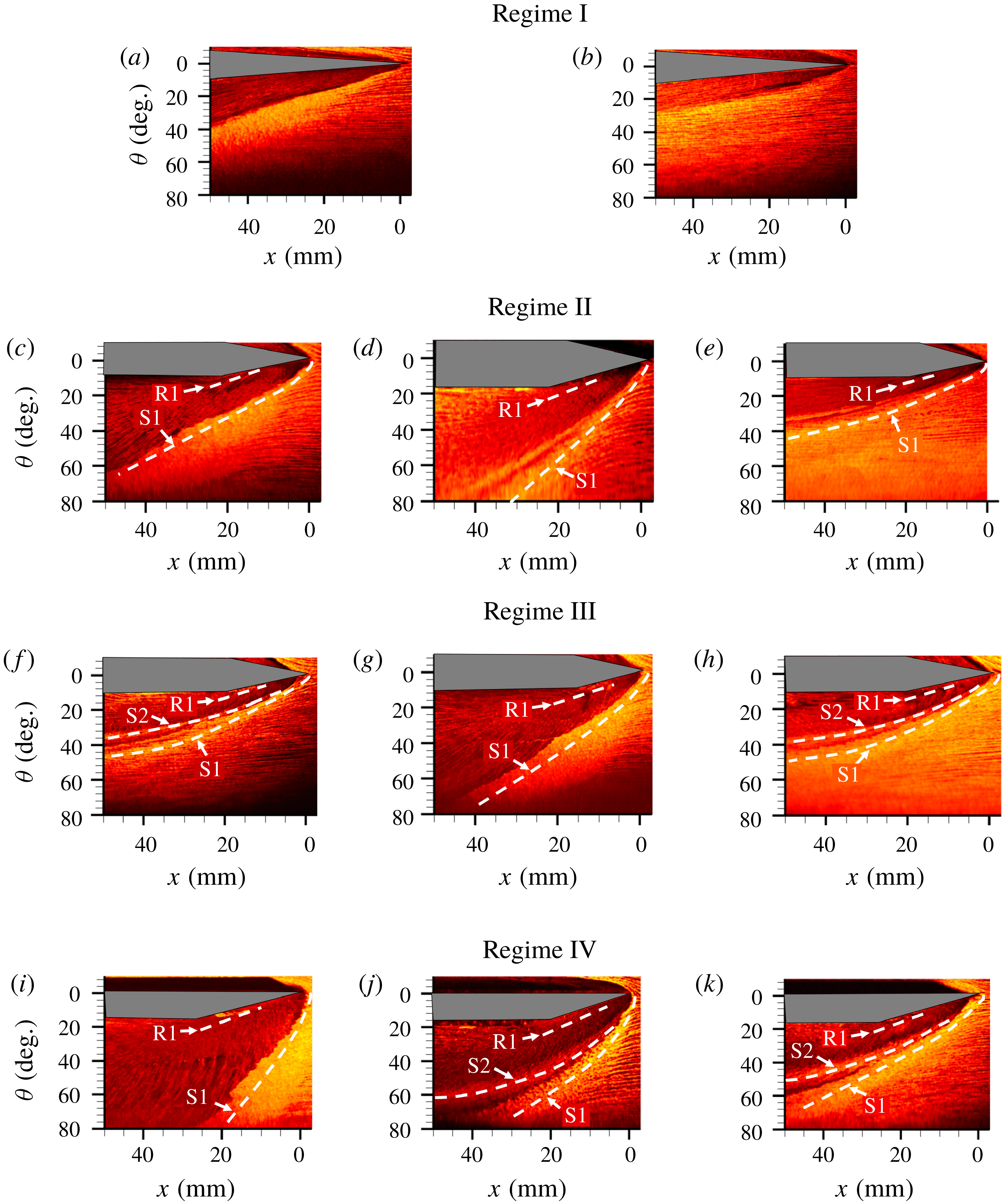
Figure 7. Flow visualizations for each fin angle. This figure contains the flow visualizations for the following configurations (fin half-angle/cylinder diameter/free-stream Mach number): (a)
![]() $5^{\circ }$
/76 mm/M2.5; (b)
$5^{\circ }$
/76 mm/M2.5; (b)
![]() $5^{\circ }$
/76 mm/M3; (c)
$5^{\circ }$
/76 mm/M3; (c)
![]() $10^{\circ }$
/76 mm/M2.5; (d)
$10^{\circ }$
/76 mm/M2.5; (d)
![]() $10^{\circ }$
/50 mm/M3; (e)
$10^{\circ }$
/50 mm/M3; (e)
![]() $10^{\circ }$
/76 mm/M3; (f)
$10^{\circ }$
/76 mm/M3; (f)
![]() $12^{\circ }$
/76 mm/M3; (g)
$12^{\circ }$
/76 mm/M3; (g)
![]() $14^{\circ }$
/76 mm/M2.5; (h)
$14^{\circ }$
/76 mm/M2.5; (h)
![]() $14^{\circ }$
/76 mm/M3; (i)
$14^{\circ }$
/76 mm/M3; (i)
![]() $20^{\circ }$
/76 mm/M2.5; (j)
$20^{\circ }$
/76 mm/M2.5; (j)
![]() $20^{\circ }$
/50 mm/M3; (k)
$20^{\circ }$
/50 mm/M3; (k)
![]() $20^{\circ }$
/76 mm/M3. Flow is from right to left.
$20^{\circ }$
/76 mm/M3. Flow is from right to left.
Fin angles
![]() $12^{\circ }$
(figure 7
f) and
$12^{\circ }$
(figure 7
f) and
![]() $14^{\circ }$
(figure 7
g–h) for the test Mach numbers used in this study are predicted to lie well within the bounds of regime III based on planar SBLI. This should mean the separated flow consists of primary and secondary separation and reattachment. It can be observed from figures 7(f) and 7(h) that while both primary separation (S1) and secondary separation (S2) are clearly visible, there is no clear indication of secondary reattachment that was observed in planar configurations. Not noticing the secondary reattachment could be due to its highly unsteady nature that causes it to get smeared in the streakline visualization or because the secondary reattachment line could be so close to the secondary or primary separation that the reattachment locus gets masked by the separation locus. The latter argument is also supported in planar fin SBLI literature in regime III (Zheltovodov Reference Zheltovodov1982), which shows that the secondary reattachment is extremely close to primary separation, making it hardly identifiable.
$14^{\circ }$
(figure 7
g–h) for the test Mach numbers used in this study are predicted to lie well within the bounds of regime III based on planar SBLI. This should mean the separated flow consists of primary and secondary separation and reattachment. It can be observed from figures 7(f) and 7(h) that while both primary separation (S1) and secondary separation (S2) are clearly visible, there is no clear indication of secondary reattachment that was observed in planar configurations. Not noticing the secondary reattachment could be due to its highly unsteady nature that causes it to get smeared in the streakline visualization or because the secondary reattachment line could be so close to the secondary or primary separation that the reattachment locus gets masked by the separation locus. The latter argument is also supported in planar fin SBLI literature in regime III (Zheltovodov Reference Zheltovodov1982), which shows that the secondary reattachment is extremely close to primary separation, making it hardly identifiable.
The streakline visualization results are shown figure 7(i–k) for the axisymmetric configuration corresponding to
![]() $\unicode[STIX]{x1D6FC}/D/M$
combinations of
$\unicode[STIX]{x1D6FC}/D/M$
combinations of
![]() $20^{\circ }$
/76 mm/2.5,
$20^{\circ }$
/76 mm/2.5,
![]() $20^{\circ }$
/50 mm/3 and
$20^{\circ }$
/50 mm/3 and
![]() $20^{\circ }$
/76 mm/3, respectively. While the first case lies well within the bounds of regime IV, the second and third lie at the boundary between regimes IV and V, which should correspond to the diminishing of secondary separation and reattachment. It can be observed from figure 7(j,k) that both primary and secondary separation can be observed in all cases. Although significant attenuation of the secondary separation was predicted in figure 7(j,k) based on Zheltovodov, no such attenuation was observed in the figures. Similar to figure 7(f–h), the
$20^{\circ }$
/76 mm/3, respectively. While the first case lies well within the bounds of regime IV, the second and third lie at the boundary between regimes IV and V, which should correspond to the diminishing of secondary separation and reattachment. It can be observed from figure 7(j,k) that both primary and secondary separation can be observed in all cases. Although significant attenuation of the secondary separation was predicted in figure 7(j,k) based on Zheltovodov, no such attenuation was observed in the figures. Similar to figure 7(f–h), the
![]() $20^{\circ }$
fin SBLIs at all the combinations of Mach number and cylinder diameters lack a secondary reattachment line. Overall, it is clear that the 3-D relief from the cylindrical surface does not have a large influence on the characteristics of the global flow regimes. Barring some minor discrepancies at the intersection of regimes IV and V, the flow fields for both cylinder diameters are consistent with the existing regime maps based on planar SBLI.
$20^{\circ }$
fin SBLIs at all the combinations of Mach number and cylinder diameters lack a secondary reattachment line. Overall, it is clear that the 3-D relief from the cylindrical surface does not have a large influence on the characteristics of the global flow regimes. Barring some minor discrepancies at the intersection of regimes IV and V, the flow fields for both cylinder diameters are consistent with the existing regime maps based on planar SBLI.
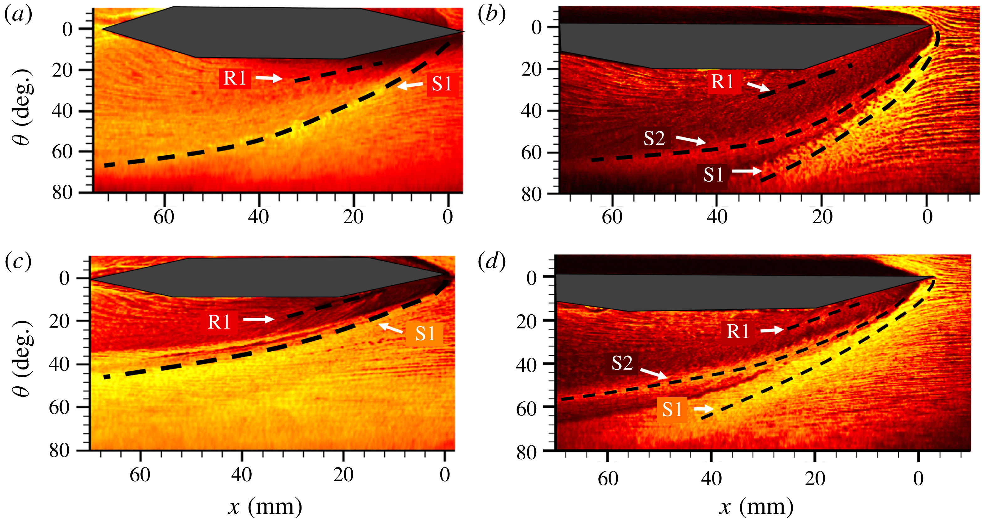
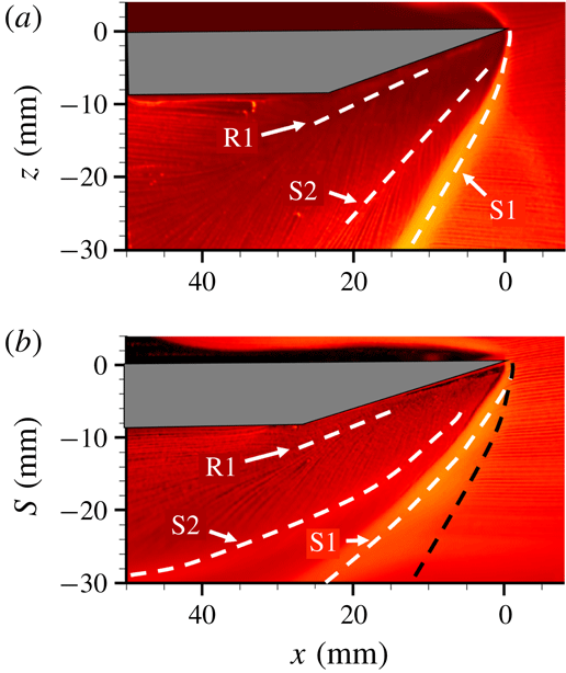
Figure 8. Unwrapped top view surface streakline visualization images of primary separation (S1), primary reattachment (R1) and secondary separation (S2) loci for combinations of: (a)
![]() $10^{\circ }$
/50 mm/3, (b)
$10^{\circ }$
/50 mm/3, (b)
![]() $20^{\circ }$
/50 mm/3, (c)
$20^{\circ }$
/50 mm/3, (c)
![]() $10^{\circ }$
/76 mm/3 and (d)
$10^{\circ }$
/76 mm/3 and (d)
![]() $20^{\circ }$
/76 mm/3.
$20^{\circ }$
/76 mm/3.
4.2 Separation locus evolution of fin-on-cylinder SBLI
The separation and reattachment loci of figure 7 reveal interesting features in the fin-on-cylinder SBLI with increasing shock strength and 3-D relief magnitude. Figure 8 shows the streakline images of the separated flow generated by two different fin angles (
![]() $\unicode[STIX]{x1D6FC}=10^{\circ }$
and
$\unicode[STIX]{x1D6FC}=10^{\circ }$
and
![]() $20^{\circ }$
) and two different cylindrical diameter (50 mm, 76 mm) that impose different 3-D relief magnitudes; the Mach number was held constant for all cases. Comparing figure 8(a,b) or (c,d), it can be observed that the primary and secondary separation loci are curved along their entirety, bending towards the streamwise direction for both fin angles. Furthermore, the curvature is more pronounced at the larger fin angle, and the curved separation loci include the entire region upstream of the expansion fan created by the fin elbow. Similarly, comparing figure 8(a,c) or (b,d), it can be observed that the curvature is more pronounced at smaller cylinder diameters (which offer greater 3-D relief). The curved nature of the primary separation loci is in stark contrast to the straight loci seen in the planar fin SBLI (Alvi & Settles Reference Alvi and Settles1992; Baldwin et al.
Reference Baldwin, Arora, Kumar and Alvi2016). In contrast to the curved separation loci, the primary reattachment loci remain largely straight across all the configurations considered, suggesting the surface curvature magnitudes used in this work have only a modest effect on the reattachment loci. As a result, the rate of growth of the separation vortex for fin SBLI on a cylindrical surface continuously decreases with downstream distance, in contrast to the near-constant growth rate in planar fin SBLI. Once the separated flow/shock system gets processed by the expansion wave from the elbow, further turning of the separation loci towards the flow direction could be observed, resulting in slower separated flow growth.
$20^{\circ }$
) and two different cylindrical diameter (50 mm, 76 mm) that impose different 3-D relief magnitudes; the Mach number was held constant for all cases. Comparing figure 8(a,b) or (c,d), it can be observed that the primary and secondary separation loci are curved along their entirety, bending towards the streamwise direction for both fin angles. Furthermore, the curvature is more pronounced at the larger fin angle, and the curved separation loci include the entire region upstream of the expansion fan created by the fin elbow. Similarly, comparing figure 8(a,c) or (b,d), it can be observed that the curvature is more pronounced at smaller cylinder diameters (which offer greater 3-D relief). The curved nature of the primary separation loci is in stark contrast to the straight loci seen in the planar fin SBLI (Alvi & Settles Reference Alvi and Settles1992; Baldwin et al.
Reference Baldwin, Arora, Kumar and Alvi2016). In contrast to the curved separation loci, the primary reattachment loci remain largely straight across all the configurations considered, suggesting the surface curvature magnitudes used in this work have only a modest effect on the reattachment loci. As a result, the rate of growth of the separation vortex for fin SBLI on a cylindrical surface continuously decreases with downstream distance, in contrast to the near-constant growth rate in planar fin SBLI. Once the separated flow/shock system gets processed by the expansion wave from the elbow, further turning of the separation loci towards the flow direction could be observed, resulting in slower separated flow growth.
It should be noted that the observed separation loci curvature is not unlike the features seen in supersonic flow past a circular cylinder (Sykes Reference Sykes1962; Voitenko, Zubkov & Panov Reference Voitenko, Zubkov and Panov1966; Ozawa & Laurence Reference Ozawa and Laurence2018) or blunt fin (Dolling & Bogdonoff Reference Dolling and Bogdonoff1982; Hung & Buning Reference Hung and Buning1985; Barnhart & Greber Reference Barnhart and Greber1997) mounted on a flat plate. The bluff bodies of the circular cylinder and blunt fin result in bow shocks that curve and weaken with increasing downstream distance as they interact with the expansion fans. Thus, the curved separation loci observed in bluff body configurations are due to the presence of expansion fans and has as nothing to do with a 3-D relief observed in a fin-on-cylinder SBLI configuration. These geometries are most similar to the region downstream of the fin elbow where the influence of the expansion fan takes over, contributing to the further inboard sweeping of the separation loci and weakening of the shock structure. In the vicinity of the compression surface of the fin, however, the curved separation loci are due to the azimuthal relief offered to the flow from the cylindrical surface curvature (referred to as 3-D relief in the text) rather than the action of expansion waves.
To further expand and quantify the separated flow modification caused by the 3-D relief effects, a direct comparison is made between a planar fin SBLI and fin-on-cylinder SBLI at identical conditions. Figure 9 compares the surface streaklines of the shock-induced separated flow obtained using a
![]() $20^{\circ }$
fin placed on a flat plate (planar fin SBLI; figure 9
a) and the same fin mounted on a 50 mm diameter half-cylinder model. The
$20^{\circ }$
fin placed on a flat plate (planar fin SBLI; figure 9
a) and the same fin mounted on a 50 mm diameter half-cylinder model. The
![]() $y$
-axis of the fin-on-cylinder SBLI configuration (figure 9
b) corresponds to the circumferential distance along the cylinder surface measured from the fin root
$y$
-axis of the fin-on-cylinder SBLI configuration (figure 9
b) corresponds to the circumferential distance along the cylinder surface measured from the fin root
![]() $(z=0)$
. The free-stream Mach number was set at 2.5 for both cases, and the incoming boundary layer thickness and
$(z=0)$
. The free-stream Mach number was set at 2.5 for both cases, and the incoming boundary layer thickness and
![]() $C_{f}$
were verified to be very similar. It can be observed that the primary separation locus in the planar SBLI case starts with a curvature in the ‘inception’ region and very shortly downstream straightens to have a linear trajectory, which is consistent with previous literature (Garg & Settles Reference Garg and Settles1996). The primary reattachment locus also exhibits a straight trajectory, though its path close to the fin leading edge is harder to delineate. Figure 9(b) shows the corresponding streakline visualization of the fin-on-cylinder SBLI overlaid with the primary separation (S1) locus of the planar case (black line). It can be observed that the S1 locus of fin-on-cylinder SBLI is always located at a shorter circumferential distance from the fin root for any streamwise location compared to the planar SBLI. This shows that for the same inviscid shock strength, the fin-on-cylinder SBLI has a smaller separated flow compared to the planar case. This difference in the S1 locus increases with downstream distance as the separation locus of the fin-on-cylinder SBLI get progressively swept towards the fin surface. Given the same fin geometry was used in the both the planar and cylindrical configurations in figure 9, the remarkable difference in the separation loci is attributed to the 3-D relief offered by the curvature of the surface rather than the expansion fan effects close to the fin elbow. Although it is difficult to delineate the contributions from the expansion fan off the fin elbow from the 3-D relief effect at downstream distances past the fin elbow
$C_{f}$
were verified to be very similar. It can be observed that the primary separation locus in the planar SBLI case starts with a curvature in the ‘inception’ region and very shortly downstream straightens to have a linear trajectory, which is consistent with previous literature (Garg & Settles Reference Garg and Settles1996). The primary reattachment locus also exhibits a straight trajectory, though its path close to the fin leading edge is harder to delineate. Figure 9(b) shows the corresponding streakline visualization of the fin-on-cylinder SBLI overlaid with the primary separation (S1) locus of the planar case (black line). It can be observed that the S1 locus of fin-on-cylinder SBLI is always located at a shorter circumferential distance from the fin root for any streamwise location compared to the planar SBLI. This shows that for the same inviscid shock strength, the fin-on-cylinder SBLI has a smaller separated flow compared to the planar case. This difference in the S1 locus increases with downstream distance as the separation locus of the fin-on-cylinder SBLI get progressively swept towards the fin surface. Given the same fin geometry was used in the both the planar and cylindrical configurations in figure 9, the remarkable difference in the separation loci is attributed to the 3-D relief offered by the curvature of the surface rather than the expansion fan effects close to the fin elbow. Although it is difficult to delineate the contributions from the expansion fan off the fin elbow from the 3-D relief effect at downstream distances past the fin elbow
![]() $(x>25~\text{mm})$
the streaklines at
$(x>25~\text{mm})$
the streaklines at
![]() $x\leqslant 25~\text{mm}$
are expected to be dominated by the 3-D relief effects. This shrinkage of the separated flow in fin-on-cylinder SBLI, compared to planar SBLI, with downstream distance is another stark manifestation of the 3-D relief from the cylindrical surface.
$x\leqslant 25~\text{mm}$
are expected to be dominated by the 3-D relief effects. This shrinkage of the separated flow in fin-on-cylinder SBLI, compared to planar SBLI, with downstream distance is another stark manifestation of the 3-D relief from the cylindrical surface.
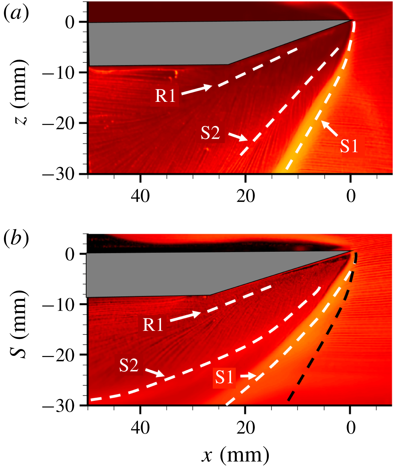
Figure 9. Top view surface streakline visualization of primary separation (S1), primary reattachment (R1) and secondary separation (S2) loci for a 25 mm tall fin on (a) flat plate, and (b) 50 mm diameter cylinder at Mach 2.5.
4.3 Mean surface pressure field
The mean surface pressure field was obtained for the specific configuration of a
![]() $20^{\circ }$
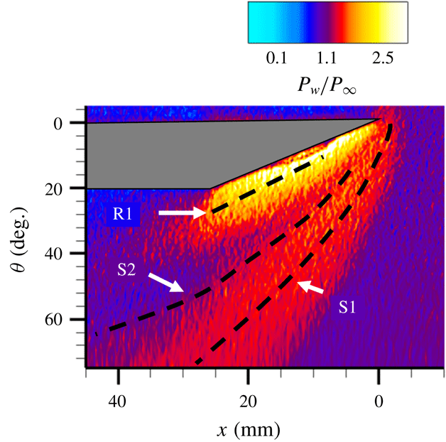
fin mounted on a 50 mm half-cylinder placed in a Mach 2.5 flow to investigate if similar manifestations of the 3-D relief are also present in the surface pressure field. This particular fin/flow configuration has been used in the majority of subsequent discussions as this correspond to regime IV, which has one of the most complex separated flow structure involving both primary and secondary separations. Figure 10 shows the mean surface pressure field, normalized by the free-stream pressure, over which the separation and reattachment loci from surface streakline images from figure 9(b) are overlaid. It can be observed that the pressure isocontours also follow curved loci, similar to the streakline patterns. A sharp pressure gradient can be observed as a blue/red interface corresponding to the upstream influence region. The primary separation locus (S1) is roughly parallel to the blue/red interface (upstream influence region), which is very similar to planar SBLI. Traversing in the azimuthal direction towards fin root (
$20^{\circ }$
fin mounted on a 50 mm half-cylinder placed in a Mach 2.5 flow to investigate if similar manifestations of the 3-D relief are also present in the surface pressure field. This particular fin/flow configuration has been used in the majority of subsequent discussions as this correspond to regime IV, which has one of the most complex separated flow structure involving both primary and secondary separations. Figure 10 shows the mean surface pressure field, normalized by the free-stream pressure, over which the separation and reattachment loci from surface streakline images from figure 9(b) are overlaid. It can be observed that the pressure isocontours also follow curved loci, similar to the streakline patterns. A sharp pressure gradient can be observed as a blue/red interface corresponding to the upstream influence region. The primary separation locus (S1) is roughly parallel to the blue/red interface (upstream influence region), which is very similar to planar SBLI. Traversing in the azimuthal direction towards fin root (
![]() $\unicode[STIX]{x1D703}=0^{\circ }$
), it can be observed that the surface pressure approximately plateaus in the primary separated flow, which is consistent with the fact that the separated flows cannot sustain a large pressure gradient. In between the secondary separation and primary reattachment, a distinct low pressure region can be observed. This low pressure region is followed by a rapid rise in pressure near reattachment and towards the fin root. Interestingly, some amount of straightening of the pressure isocontours may be observed near the reattachment locus close to the fin root. This is similar to the relatively straight reattachment locus observed in the streakline visualization imaging.
$\unicode[STIX]{x1D703}=0^{\circ }$
), it can be observed that the surface pressure approximately plateaus in the primary separated flow, which is consistent with the fact that the separated flows cannot sustain a large pressure gradient. In between the secondary separation and primary reattachment, a distinct low pressure region can be observed. This low pressure region is followed by a rapid rise in pressure near reattachment and towards the fin root. Interestingly, some amount of straightening of the pressure isocontours may be observed near the reattachment locus close to the fin root. This is similar to the relatively straight reattachment locus observed in the streakline visualization imaging.
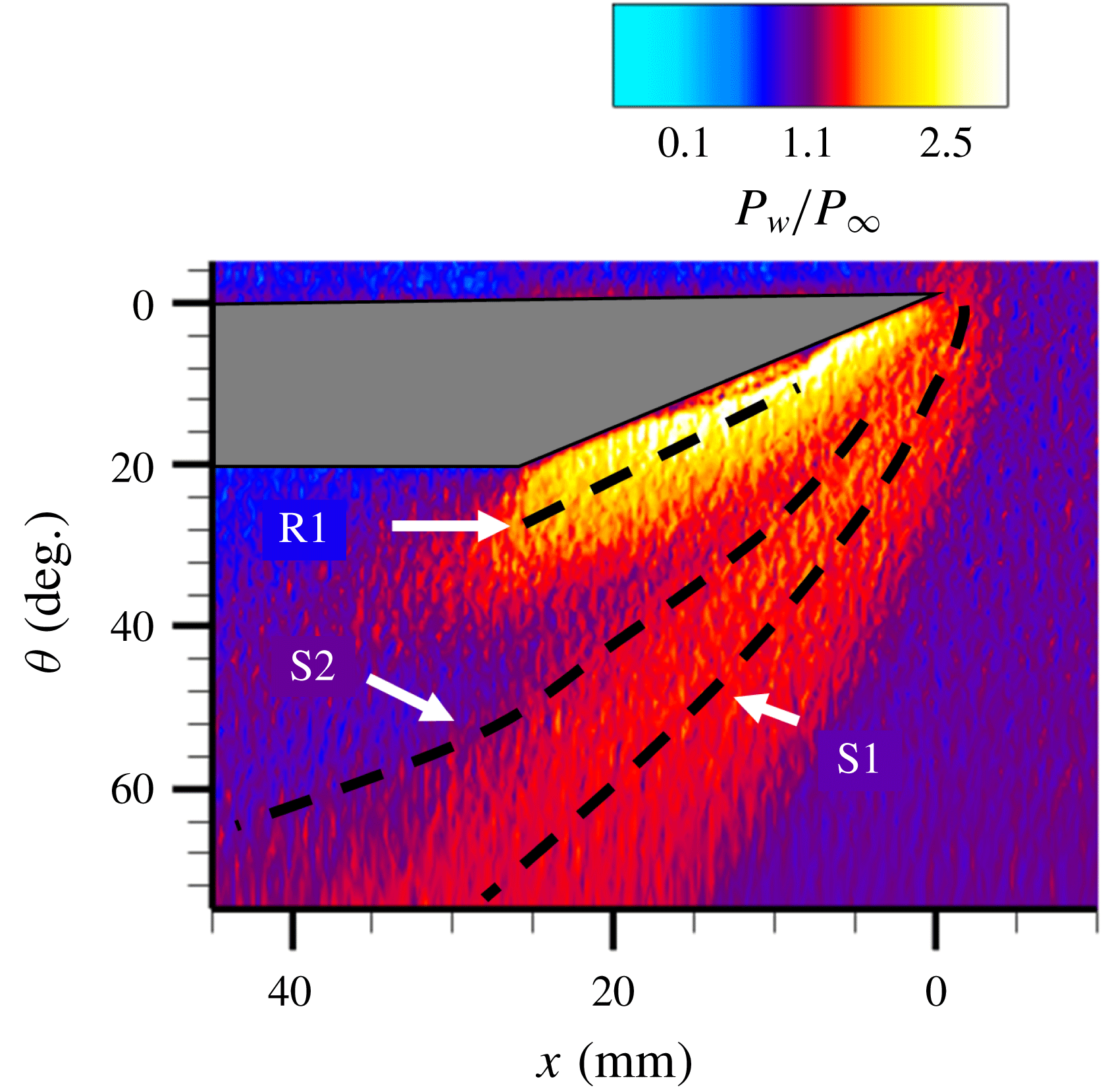
Figure 10. Unwrapped surface mean wall static pressure fields of the fin-on-cylinder SBLI. The separation and reattachment loci are overlaid from figure 9(b).
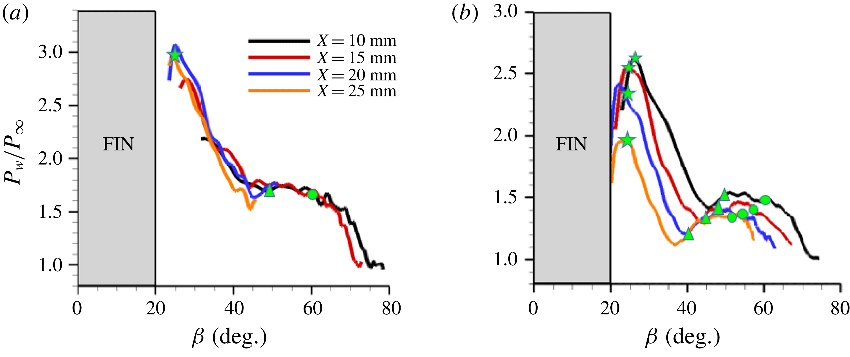
The pressure profiles along different streamwise locations downstream of the fin are plotted in the conical coordinates with respect to the polar angle
![]() $\unicode[STIX]{x1D6FD}$
to quantify how the pressure profiles evolve with downstream distance. For the fin-on-cylinder SBLI, the polar angle was defined from the unwrapped images using
$\unicode[STIX]{x1D6FD}$
to quantify how the pressure profiles evolve with downstream distance. For the fin-on-cylinder SBLI, the polar angle was defined from the unwrapped images using
where
![]() $s$
is the circumferential distance measured from
$s$
is the circumferential distance measured from
![]() $z=0$
. Figure 11 shows the comparison between wall pressure profiles for the planar SBLI configuration (figure 11
a) and the corresponding pressure profiles from fin-on-cylinder SBLI (figure 11
b) obtained at identical fin configuration and Mach number
$z=0$
. Figure 11 shows the comparison between wall pressure profiles for the planar SBLI configuration (figure 11
a) and the corresponding pressure profiles from fin-on-cylinder SBLI (figure 11
b) obtained at identical fin configuration and Mach number
![]() $(M=2.5)$
. Broadly, the pressure profiles of fin-on-cylinder and planar SBLI look qualitatively similar in terms of their evolution along the azimuthal direction: an initial pressure rise was observed close to primary separation S1 (marked by
$(M=2.5)$
. Broadly, the pressure profiles of fin-on-cylinder and planar SBLI look qualitatively similar in terms of their evolution along the azimuthal direction: an initial pressure rise was observed close to primary separation S1 (marked by
![]() $o$
), followed by a plateau within the primary separation through secondary separation S2 (marked by
$o$
), followed by a plateau within the primary separation through secondary separation S2 (marked by
![]() $\unicode[STIX]{x0394}$
), and a dip, and subsequent steep increase near reattachment R1 (marked by
$\unicode[STIX]{x0394}$
), and a dip, and subsequent steep increase near reattachment R1 (marked by
![]() $\star$
) and close to the fin root. The important difference, however, is that whereas all the profiles for the planar SBLI collapse into a single curve with respect to
$\star$
) and close to the fin root. The important difference, however, is that whereas all the profiles for the planar SBLI collapse into a single curve with respect to
![]() $\unicode[STIX]{x1D6FD}$
, owing to the quasi-conical symmetry of the SBLI, such a collapse was not observed in the fin-on-cylinder SBLI. It should be remarked that the authors also tried a different definition of
$\unicode[STIX]{x1D6FD}$
, owing to the quasi-conical symmetry of the SBLI, such a collapse was not observed in the fin-on-cylinder SBLI. It should be remarked that the authors also tried a different definition of
![]() $\unicode[STIX]{x1D6FD}$
using the top view images without unwrapping as well as a modified definition used by Arora et al. (Reference Arora, Alvi and Ali2016) and Baldwin et al. (Reference Baldwin, Arora, Kumar and Alvi2016), but there was no collapse in those profiles as well. This shows that the quasi-conical symmetry is lost for the fin-on-cylinder SBLI configuration in the region encompassing the primary and secondary separations. Interestingly, moving closer to the fin root, it can be observed that the maximum in the pressure that occurs towards the fin root shows a lot of consistency in
$\unicode[STIX]{x1D6FD}$
using the top view images without unwrapping as well as a modified definition used by Arora et al. (Reference Arora, Alvi and Ali2016) and Baldwin et al. (Reference Baldwin, Arora, Kumar and Alvi2016), but there was no collapse in those profiles as well. This shows that the quasi-conical symmetry is lost for the fin-on-cylinder SBLI configuration in the region encompassing the primary and secondary separations. Interestingly, moving closer to the fin root, it can be observed that the maximum in the pressure that occurs towards the fin root shows a lot of consistency in
![]() $\unicode[STIX]{x1D6FD}$
with increasing streamwise distance. This suggests that the quasi-conical symmetry that was lost in the bulk of the separated flow region was partly recovered closer to the fin root. This observation is also corroborated by a near-linear reattachment locus observed in figure 9. Due to the curved nature of the separation loci, the downstream distance
$\unicode[STIX]{x1D6FD}$
with increasing streamwise distance. This suggests that the quasi-conical symmetry that was lost in the bulk of the separated flow region was partly recovered closer to the fin root. This observation is also corroborated by a near-linear reattachment locus observed in figure 9. Due to the curved nature of the separation loci, the downstream distance
![]() $x$
for the fin-on-cylinder SBLI was measured from the fin leading edge since a VCO that is typically used in planar fin SBLI could not be easily identified. This definition, however, does not alter the conclusions made.
$x$
for the fin-on-cylinder SBLI was measured from the fin leading edge since a VCO that is typically used in planar fin SBLI could not be easily identified. This definition, however, does not alter the conclusions made.
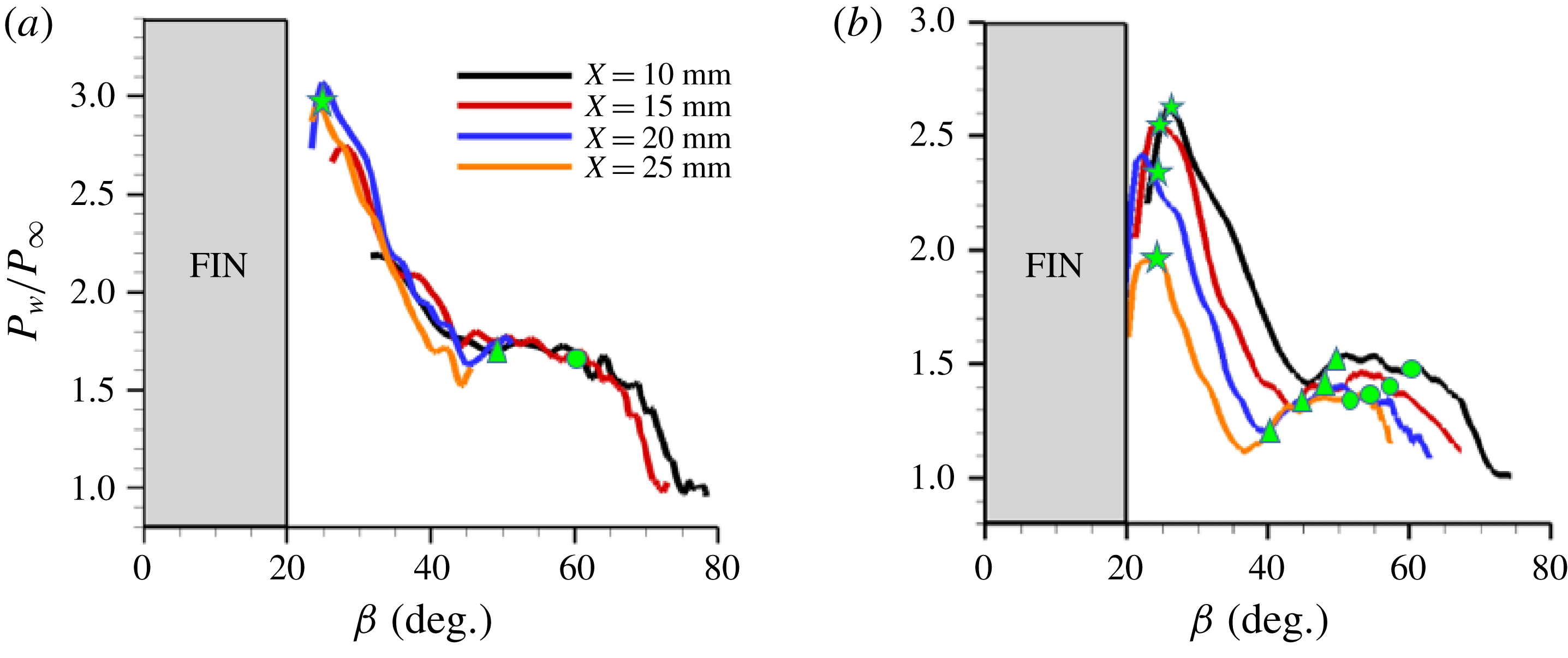
Figure 11. Mean wall static pressure profiles along spanwise (for planar fin SBLI) and azimuthal (for fin-on-cylinder SBLI) direction at different streamwise locations. (a) Planar fin SBLI wall pressure profiles, and (b) fin-on-cylinder SBLI wall pressure profiles. The values are normalized by free-stream pressure.
Quantitative examination of the pressure profiles of the planar SBLI in figure 11(a) shows that the pressure profiles at different streamwise locations collapse very well in the conical coordinates, which means that the magnitude of the pressure rise remains unaltered with downstream distance. This shows that the separation and reattachment shock systems maintain their strengths with downstream distance, which is also evident from the identical
![]() $\unicode[STIX]{x1D6FD}$
locations of the S1, S2 and R1 with downstream distance. However, the pressure values across the fin-on-cylinder SBLI monotonically decrease with downstream distance suggesting a decrease in the separation/reattachment shock strength with downstream distance. For example, the relative plateau between S1 and S2 decreases from 1.5
$\unicode[STIX]{x1D6FD}$
locations of the S1, S2 and R1 with downstream distance. However, the pressure values across the fin-on-cylinder SBLI monotonically decrease with downstream distance suggesting a decrease in the separation/reattachment shock strength with downstream distance. For example, the relative plateau between S1 and S2 decreases from 1.5
![]() $p_{\infty }$
to 1.35
$p_{\infty }$
to 1.35
![]() $p_{\infty }$
between
$p_{\infty }$
between
![]() $x=10~\text{mm}$
and
$x=10~\text{mm}$
and
![]() $x=20~\text{mm}$
. Correspondingly, the peak pressure after R1 (
$x=20~\text{mm}$
. Correspondingly, the peak pressure after R1 (
![]() $\unicode[STIX]{x1D6FD}\approx 26^{\circ }$
) close to the fin root decreases from 2.65
$\unicode[STIX]{x1D6FD}\approx 26^{\circ }$
) close to the fin root decreases from 2.65
![]() $p_{\infty }$
to 2.4
$p_{\infty }$
to 2.4
![]() $p_{\infty }$
. The steep pressure dip between
$p_{\infty }$
. The steep pressure dip between
![]() $x=20~\text{mm}$
and
$x=20~\text{mm}$
and
![]() $x=25~\text{mm}$
at
$x=25~\text{mm}$
at
![]() $\unicode[STIX]{x1D6FD}\approx 26^{\circ }$
is believed to be due to viscous interactions that can advance the start of the expansion fan close to the fin root. More interestingly, the minima in pressure between S2 and R1 exhibit larger dips with respect to the plateau value with increasing downstream distance. For example, the minima are only mildly distinguishable from the plateau pressure (similar to planar SBLI) at
$\unicode[STIX]{x1D6FD}\approx 26^{\circ }$
is believed to be due to viscous interactions that can advance the start of the expansion fan close to the fin root. More interestingly, the minima in pressure between S2 and R1 exhibit larger dips with respect to the plateau value with increasing downstream distance. For example, the minima are only mildly distinguishable from the plateau pressure (similar to planar SBLI) at
![]() $x=10~\text{mm}$
; the dip is very pronounced at
$x=10~\text{mm}$
; the dip is very pronounced at
![]() $x=25~\text{mm}$
where the value is 20 % lower than the plateau value between S1 and S2. Subsequent sections will discuss the off-body physical features causing the pressure dip and the significance of the large magnitude of the dip with downstream distance.
$x=25~\text{mm}$
where the value is 20 % lower than the plateau value between S1 and S2. Subsequent sections will discuss the off-body physical features causing the pressure dip and the significance of the large magnitude of the dip with downstream distance.
Figure 11(a) also shows that the loci of the separation and reattachment occur at the same
![]() $\unicode[STIX]{x1D6FD}$
locations with downstream distance in planar SBLI owing to their quasi-conical symmetry. This also means that the S1, S2 and R1 occur at the same respective wall pressures at all streamwise locations. Furthermore, the pressure beneath S1 of 1.65
$\unicode[STIX]{x1D6FD}$
locations with downstream distance in planar SBLI owing to their quasi-conical symmetry. This also means that the S1, S2 and R1 occur at the same respective wall pressures at all streamwise locations. Furthermore, the pressure beneath S1 of 1.65
![]() $p_{\infty }$
is highly consistent with that predicted by the free interaction theory (1.62
$p_{\infty }$
is highly consistent with that predicted by the free interaction theory (1.62
![]() $p_{\infty }$
) using the constant
$p_{\infty }$
) using the constant
![]() $F=4.2$
as suggested by previous researchers (Babinsky & Harvey Reference Babinsky and Harvey2011). In contrast, the mean wall pressure at S1, S2 and R1 for the fin-on-cylinder SBLI (figure 11
b) continuously decreases with downstream distance. Furthermore, while the variation in the pressure beneath the S1 locus between
$F=4.2$
as suggested by previous researchers (Babinsky & Harvey Reference Babinsky and Harvey2011). In contrast, the mean wall pressure at S1, S2 and R1 for the fin-on-cylinder SBLI (figure 11
b) continuously decreases with downstream distance. Furthermore, while the variation in the pressure beneath the S1 locus between
![]() $x=10~\text{mm}$
to 20 mm was
$x=10~\text{mm}$
to 20 mm was
![]() ${\approx}8\,\%$
, the corresponding variation in S2 was much higher
${\approx}8\,\%$
, the corresponding variation in S2 was much higher
![]() $({\approx}23\,\%)$
. Correspondingly, the wall pressure decreased by approximately 9 % beneath R1 between the same streamwise locations.
$({\approx}23\,\%)$
. Correspondingly, the wall pressure decreased by approximately 9 % beneath R1 between the same streamwise locations.
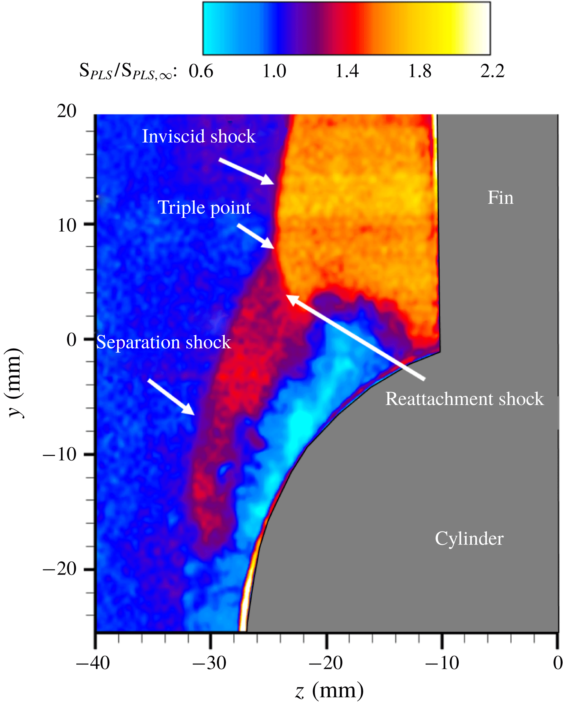
Figure 12. A representative instantaneous PLS field after background subtraction and laser sheet correction obtained at
![]() $x=25~\text{mm}$
. The flow direction is into the page.
$x=25~\text{mm}$
. The flow direction is into the page.
4.4 Off-body SBLI shock/flow field structure
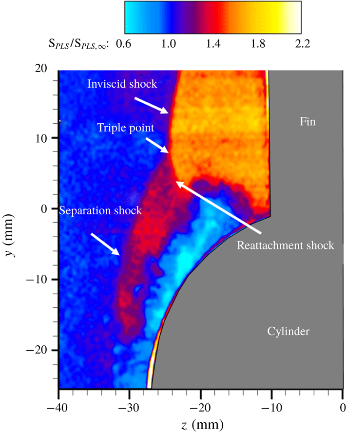
The objectives of the PLS study are to delineate the off-body flow features and the shock structure of the fin interactions and their evolution with downstream distance. PLS imaging was performed in spanwise–wall-normal planes to provide a cross-sectional view of the shock wave and the separated flow. Figure 12 shows an instantaneous snapshot of a PLS image off the cylinder surface, obtained at
![]() $x=25~\text{mm}$
and a free-stream Mach number of 2.5. A clear presence of a
$x=25~\text{mm}$
and a free-stream Mach number of 2.5. A clear presence of a
![]() $\unicode[STIX]{x1D706}$
-shock can be observed in figure 12, indicated by the distinct regions of free-stream-normalized PLS ratio. The inviscid shock is identified by the interface with strongest signal jump because of the largest density downstream of the shock. There is a noticeable triple point in the flow from which the separation and reattachment legs of the
$\unicode[STIX]{x1D706}$
-shock can be observed in figure 12, indicated by the distinct regions of free-stream-normalized PLS ratio. The inviscid shock is identified by the interface with strongest signal jump because of the largest density downstream of the shock. There is a noticeable triple point in the flow from which the separation and reattachment legs of the
![]() $\unicode[STIX]{x1D706}$
-shock emanate. Since the shock strength in these portions is smaller, there is a smaller density jump across them resulting in weaker PLS signals compared to downstream of the inviscid shock. It should be noted that the density jump across the separation and reattachment shock is still large enough to establish their instantaneous and mean locations in all images. A slip stream also emanates from the triple point and is incident on the cylinder surface close to the fin root. Because of the very small gas density difference between the slip stream and the surrounding, it is not very clear in the PLS images. Between the separation and reattachment shocks is a large region of turbulent flow with substantially low signals, which corresponds to the separated flow. All these flow features exhibit a tremendous similarity with those of a canonical planar fin SBLI that was discussed in § 1 (figure 1). This shows that there are no qualitative global changes in the shock/separated flow units that develop over the cylindrical surface due to fin SBLI.
$\unicode[STIX]{x1D706}$
-shock emanate. Since the shock strength in these portions is smaller, there is a smaller density jump across them resulting in weaker PLS signals compared to downstream of the inviscid shock. It should be noted that the density jump across the separation and reattachment shock is still large enough to establish their instantaneous and mean locations in all images. A slip stream also emanates from the triple point and is incident on the cylinder surface close to the fin root. Because of the very small gas density difference between the slip stream and the surrounding, it is not very clear in the PLS images. Between the separation and reattachment shocks is a large region of turbulent flow with substantially low signals, which corresponds to the separated flow. All these flow features exhibit a tremendous similarity with those of a canonical planar fin SBLI that was discussed in § 1 (figure 1). This shows that there are no qualitative global changes in the shock/separated flow units that develop over the cylindrical surface due to fin SBLI.
The evolution of the mean SBLI shock/flow features with downstream distance are studied through the ensemble-mean and r.m.s. free-stream-normalized PLS images, shown in figures 13 and 14, respectively. By comparing figure 13(a–d), it can be observed that the inviscid shock moves progressively away from the fin face (negative
![]() $z$
-direction) with downstream distance. Close to the fin leading edge (figures 13
a,b and 14
a,b), the shape of the inviscid shock evolves from being straight along the bulk of the fin height to being increasingly curved especially towards the fin top edge. This curvature towards the fin top edge is due to the dissipation of shock strength caused by the finite height of the fin. The effect of the finite fin height also contributes to weakening the bulk of inviscid shock at more downstream locations, as visually observed from the colour gradients across the inviscid shock, and render an increasing curvature to the inviscid shock with downstream distance. Alongside the lateral displacement of the inviscid shock with downstream distance, the location of the triple point moves laterally without appreciable wall-normal displacement. For instance, the triple point (visualized better from figure 14) is at
$z$
-direction) with downstream distance. Close to the fin leading edge (figures 13
a,b and 14
a,b), the shape of the inviscid shock evolves from being straight along the bulk of the fin height to being increasingly curved especially towards the fin top edge. This curvature towards the fin top edge is due to the dissipation of shock strength caused by the finite height of the fin. The effect of the finite fin height also contributes to weakening the bulk of inviscid shock at more downstream locations, as visually observed from the colour gradients across the inviscid shock, and render an increasing curvature to the inviscid shock with downstream distance. Alongside the lateral displacement of the inviscid shock with downstream distance, the location of the triple point moves laterally without appreciable wall-normal displacement. For instance, the triple point (visualized better from figure 14) is at
![]() $(y,z)=(3~\text{mm},-7~\text{mm})$
at
$(y,z)=(3~\text{mm},-7~\text{mm})$
at
![]() $x=10~\text{mm}$
and
$x=10~\text{mm}$
and
![]() $(y,z)=(7~\text{mm},-18~\text{mm})$
at
$(y,z)=(7~\text{mm},-18~\text{mm})$
at
![]() $x=20~\text{mm}$
and with hardly any change in
$x=20~\text{mm}$
and with hardly any change in
![]() $y$
-location between
$y$
-location between
![]() $x=20~\text{mm}$
and
$x=20~\text{mm}$
and
![]() $x=25~\text{mm}$
. It is interesting to note that region near the surface of the cylinder is beginning to capture the canonical airfoil shape of the primary separation, especially seen in figure 13(c,d). The secondary separation vortex is not visible in figure 13(c,d) as it is masked by the laser reflection from the model surface and also cannot be distinguished from the primary separation vortex due to the lack of PLS signals in these viscous regions. Figure 13(c,d) also shows that the S1 lies close to the trailing edge of the primary separation vortex, and S2 lies close to the middle of the primary separation vortex, which is consistent with the planar SBLI literature. The reattachment location R1 lies where the leading edge of the primary separation vortex meets the cylinder surface, which is also consistent with the planar SBLI literature.
$x=25~\text{mm}$
. It is interesting to note that region near the surface of the cylinder is beginning to capture the canonical airfoil shape of the primary separation, especially seen in figure 13(c,d). The secondary separation vortex is not visible in figure 13(c,d) as it is masked by the laser reflection from the model surface and also cannot be distinguished from the primary separation vortex due to the lack of PLS signals in these viscous regions. Figure 13(c,d) also shows that the S1 lies close to the trailing edge of the primary separation vortex, and S2 lies close to the middle of the primary separation vortex, which is consistent with the planar SBLI literature. The reattachment location R1 lies where the leading edge of the primary separation vortex meets the cylinder surface, which is also consistent with the planar SBLI literature.
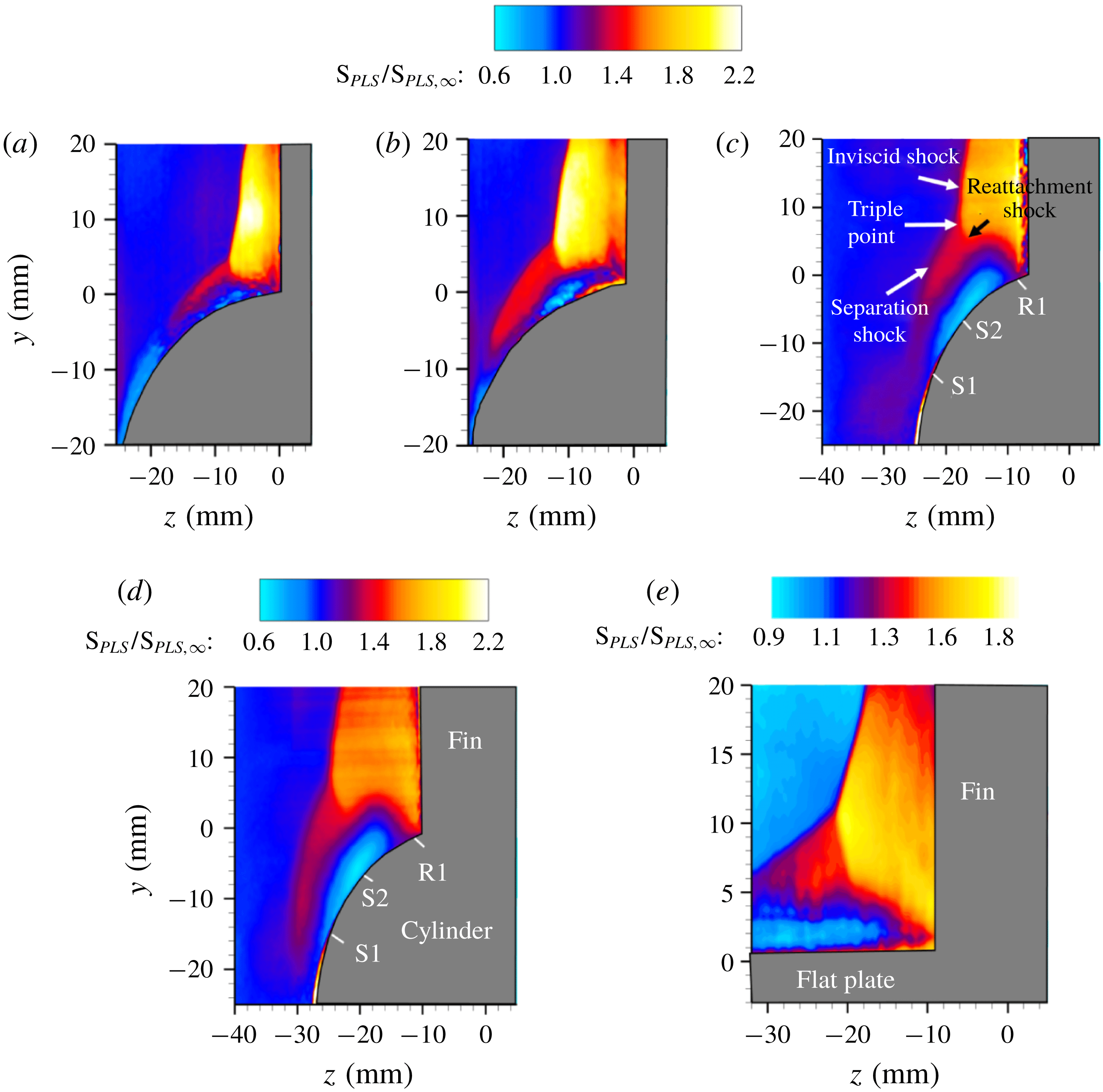
Figure 13. Ensemble averaged free-stream-normalized PLS images at different streamwise locations: (a)
![]() $x=10~\text{mm}$
; (b)
$x=10~\text{mm}$
; (b)
![]() $x=15~\text{mm}$
; (c)
$x=15~\text{mm}$
; (c)
![]() $x=20~\text{mm}$
; (d)
$x=20~\text{mm}$
; (d)
![]() $x=25~\text{mm}$
; and (e)
$x=25~\text{mm}$
; and (e)
![]() $x=25~\text{mm}$
, planar fin SBLI. Flow is into the page.
$x=25~\text{mm}$
, planar fin SBLI. Flow is into the page.
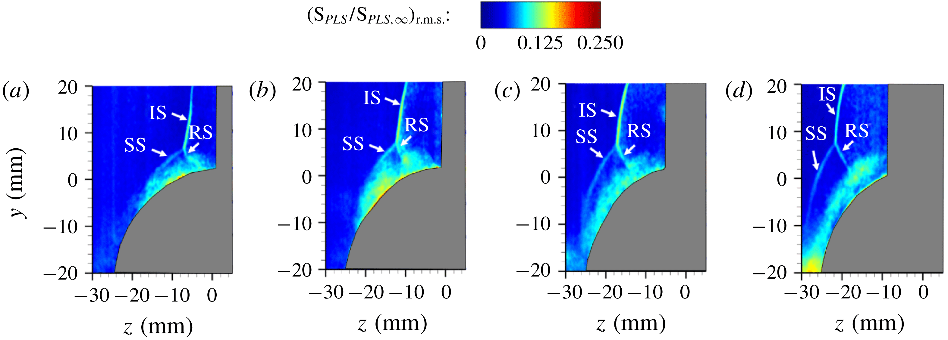
Figure 14. Normalized PLS r.m.s. images at different streamwise locations: (a)
![]() $x=10~\text{mm}$
; (b)
$x=10~\text{mm}$
; (b)
![]() $x=15~\text{mm}$
; (c)
$x=15~\text{mm}$
; (c)
![]() $x=20~\text{mm}$
; (d)
$x=20~\text{mm}$
; (d)
![]() $x=25~\text{mm}$
. The abbreviations IS, SS and RS refer to incident shock, separation shock, and reattachment shock, respectively. Flow is into the page.
$x=25~\text{mm}$
. The abbreviations IS, SS and RS refer to incident shock, separation shock, and reattachment shock, respectively. Flow is into the page.
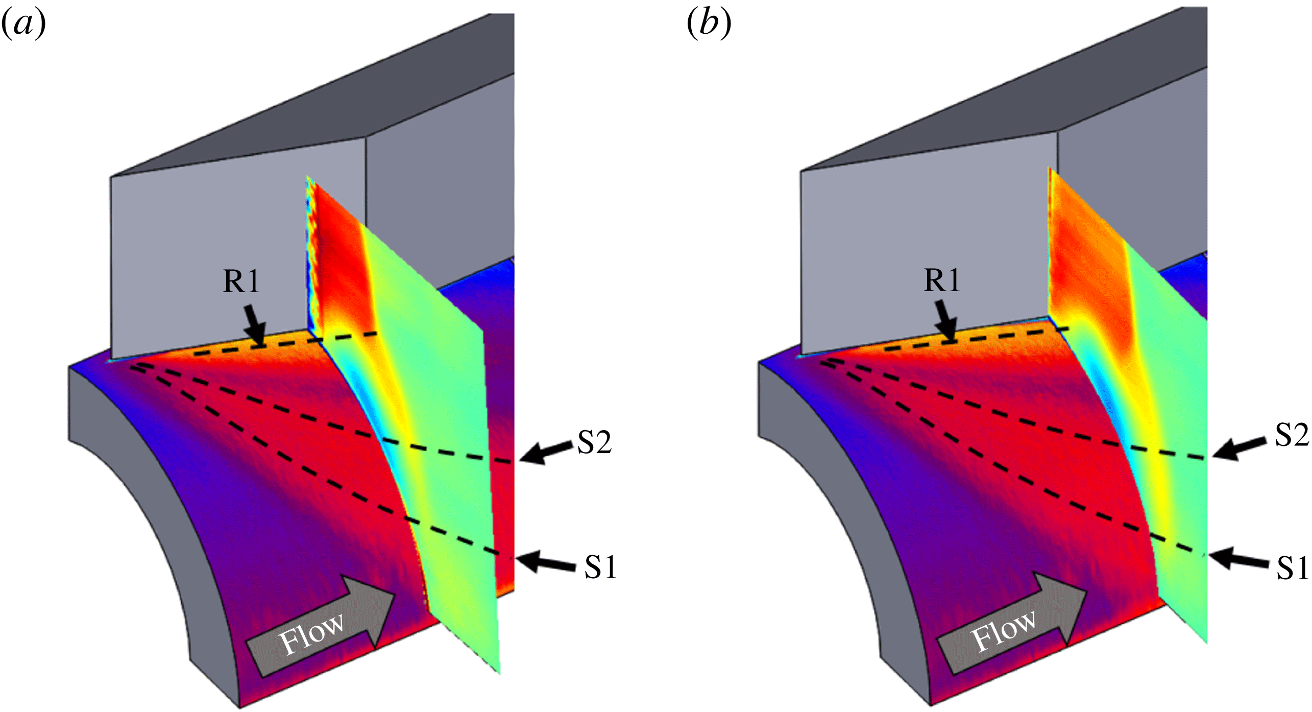
Figure 15. Simultaneous visualization of surface pressure field and off-body features of the fin-on-cylinder SBLI at: (a)
![]() $x=20~\text{mm}$
, and (b)
$x=20~\text{mm}$
, and (b)
![]() $x=25~\text{mm}$
.
$x=25~\text{mm}$
.
The separation shock, as observed from the mean and r.m.s. images in figures 13 and 14, exhibits several interesting trends with downstream distance. At locations close to the fin leading edge where the triple point is close to the fin surface, the separation shock appears with a well-defined boundary and the separation shock foot appears to reach the cylinder surface. With increasing downstream distance, the separation shock appears to wrap around the cylinder surface over larger circumferential distances. For instance, visually extrapolating the separation shock in figures 13(c) and 14(c) shows the separation shock tangentially grazing the cylinder surface at
![]() $x=20~\text{mm}$
. Farther downstream, in figures 13(d) and 14(d), the separation shock foot appears to skip the cylindrical surface almost entirely. Concomitant with the lateral motion of the separation shock foot, the separation shock also becomes increasingly steeper with downstream distance. Such large-scale changes in the separation shock structure was not observed in the planar fin SBLI, where the cross-sectional PLS image at
$x=20~\text{mm}$
. Farther downstream, in figures 13(d) and 14(d), the separation shock foot appears to skip the cylindrical surface almost entirely. Concomitant with the lateral motion of the separation shock foot, the separation shock also becomes increasingly steeper with downstream distance. Such large-scale changes in the separation shock structure was not observed in the planar fin SBLI, where the cross-sectional PLS image at
![]() $x=25~\text{mm}$
shows that the separation shock is straight (figure 13
e). It should be noted that all these streamwise locations are upstream of the fin elbow, which ensures that none of these locations are processed by expansion waves. Thus, the steepening and other modifications to the separation shock (discussed subsequently) at large downstream distances are due to the 3-D relief offered by the cylindrical surface to the separation shock.
$x=25~\text{mm}$
shows that the separation shock is straight (figure 13
e). It should be noted that all these streamwise locations are upstream of the fin elbow, which ensures that none of these locations are processed by expansion waves. Thus, the steepening and other modifications to the separation shock (discussed subsequently) at large downstream distances are due to the 3-D relief offered by the cylindrical surface to the separation shock.
The mean PLS images were overlaid on the mean wall pressure fields to discern the correspondence of the off-body SBLI structure and the surface pressure signatures. Of interest in this study are the streamwise locations
![]() $x=20~\text{mm}$
and
$x=20~\text{mm}$
and
![]() $x=25~\text{mm}$
, where the separation shocks wrap around the cylinder and exhibit the large curvature. Figure 15(a,b) shows the overlaid fields of PLS and pressure fields, at
$x=25~\text{mm}$
, where the separation shocks wrap around the cylinder and exhibit the large curvature. Figure 15(a,b) shows the overlaid fields of PLS and pressure fields, at
![]() $x=20~\text{mm}$
and
$x=20~\text{mm}$
and
![]() $x=25~\text{mm}$
, respectively. It can be observed from figure 15(a,b) that the primary separation line S1 originates after some azimuthal distance away from the shock foot. The pressure rise from the separation shock, however, occurs immediately downstream of the separation shock foot, as shown in figure 15. The shear layer over the primary separation approximately corresponds to the yellow band of the PLS overlays, and the location where it meets the cylinder surface is very close to the reattachment location, which also coincides with the high pressure region next to the fin root. The primary separation vortex is the blue/green airfoil in the PLS overlays of figure 15(a,b). The pressure dip between S2 and R1 lies beneath the core of the primary separation vortex, which is also consistent with the primary separation vortex core as reported in planar SBLI studies (Hung Reference Hung1985; Alvi & Settles Reference Alvi and Settles1992; Fang et al.
Reference Fang, Lu, Yao and Zheltovodov2017). The increasingly larger dip in pressure with downstream distance suggests that the primary separation vortex possibly gains strength or become increasingly more coherent with downstream distance in fin-on-cylinder SBLI, unlike a near constant strength in planar SBLI.
$x=25~\text{mm}$
, respectively. It can be observed from figure 15(a,b) that the primary separation line S1 originates after some azimuthal distance away from the shock foot. The pressure rise from the separation shock, however, occurs immediately downstream of the separation shock foot, as shown in figure 15. The shear layer over the primary separation approximately corresponds to the yellow band of the PLS overlays, and the location where it meets the cylinder surface is very close to the reattachment location, which also coincides with the high pressure region next to the fin root. The primary separation vortex is the blue/green airfoil in the PLS overlays of figure 15(a,b). The pressure dip between S2 and R1 lies beneath the core of the primary separation vortex, which is also consistent with the primary separation vortex core as reported in planar SBLI studies (Hung Reference Hung1985; Alvi & Settles Reference Alvi and Settles1992; Fang et al.
Reference Fang, Lu, Yao and Zheltovodov2017). The increasingly larger dip in pressure with downstream distance suggests that the primary separation vortex possibly gains strength or become increasingly more coherent with downstream distance in fin-on-cylinder SBLI, unlike a near constant strength in planar SBLI.
5 Discussion
The results described above show several global similarities between fin-on-cylinder and planar fin SBLI in terms of preserving the separation regimes and SBLI layout, and strong differences in the structure of the SBLI and separation topology between the two cases. While the primary feature of the fin-on-cylinder SBLI is the 3-D relief (additional room along azimuthal direction) offered by the curved surface, the mechanisms that cause the observed similarities and differences are unknown. The outstanding questions include: (i) Why do the separation regimes remain the same between fin-on-cylinder and planar SBLI configurations? (ii) Why does the separated flow growth rate diminish with downstream distance for fin-on-cylinder configuration? And why is the overall separated flow extent considerably smaller than planar fin SBLI? (iii) What is the role of the finite fin height in determining the separated flow topology and shock structure? (iv) How would the SBLI unit evolve with changing geometric and flow parameters? (v) How does the separated flow evolve downstream of the locations where the separation shock wraps around the cylinder and completely skips striking the cylinder surface? The answers to these questions are addressed in the following.
Separation regimes in fin-on-cylinder SBLI
First, the consistency in the separation regime between planar fin SBLI and fin-on-cylinder SBLI is addressed. To explain the consistency, it should be noted that the flow separation and reattachment are primarily controlled by the inflow parameters and shock strength, and are initiated close to the leading edge of the fin. Hence, the separated flow regime is essentially fixed by the flow interactions close to fin leading edge. Close to the leading edge, the spanwise distance of the inviscid shock and separation line from the fin is significantly smaller than the radius of curvature of the cylinder. Hence, the cylindrical surface presents essentially a ‘flat surface’ to the incoming flow at these small distances from the leading edge, which makes the interactions almost identical to those in planar fin SBLI. This preserves the separation regimes between the fin-on-cylinder and planar fin SBLIs, as observed in figure 6. Support for this argument comes from the similarity of the pressure profiles and separation/reattachment
![]() $\unicode[STIX]{x1D6FD}$
-locations of fin-on-cylinder SBLI at
$\unicode[STIX]{x1D6FD}$
-locations of fin-on-cylinder SBLI at
![]() $x=10~\text{mm}$
and the planar SBLI, as observed in figure 11, suggesting that the cylinder curvature does not influence the separated flow topology near the fin leading edge.
$x=10~\text{mm}$
and the planar SBLI, as observed in figure 11, suggesting that the cylinder curvature does not influence the separated flow topology near the fin leading edge.
Inviscid fin-on-cylinder shock structure
The second issue to address is the mechanisms that cause the separated flow growth rate to diminish with downstream distance. First the mechanisms from the 3-D relief (extra room along the azimuthal direction) offered by the cylindrical surface are expounded. We hypothesize that the 3-D relief impacts the fin-on-cylinder SBLI unit in two ways: one due to the modification of the inviscid shock strength/structure (as discussed in § 2), and the other from the viscous interactions that are impacted by the inviscid shock and cylinder curvature. Hence, the 3-D relief effect is analysed by investigating the changes introduced to the inviscid shock and the viscous response generated by the shock interactions with the boundary layer in the presence of cylinder curvature.
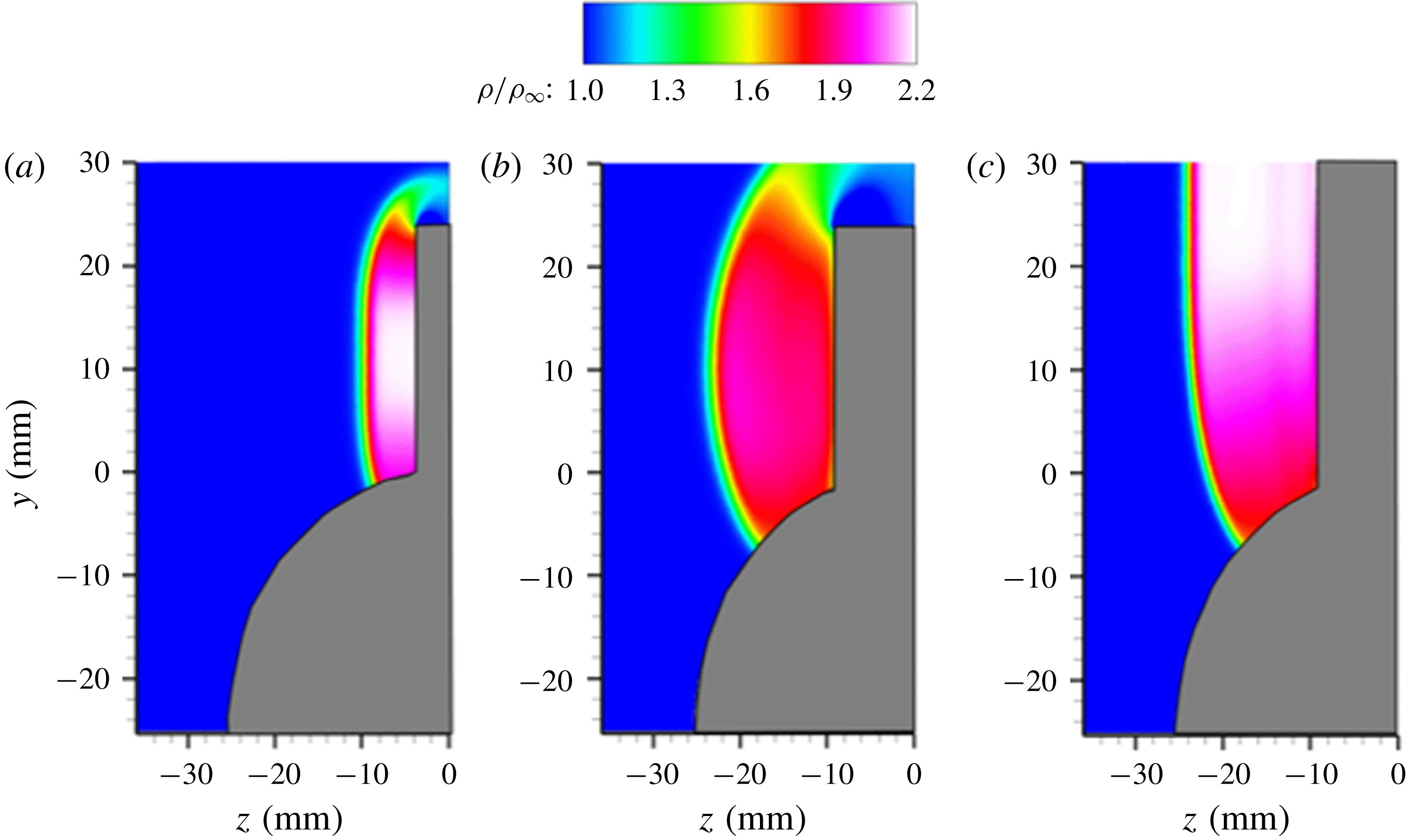
Figure 16. Density fields illustrating the fin-on-cylinder shock structure from Euler simulations: (a) 25 mm tall fin at
![]() $x=10~\text{mm}$
; (b) 25 mm tall fin at
$x=10~\text{mm}$
; (b) 25 mm tall fin at
![]() $x=25~\text{mm}$
; (c) infinitely tall fin at
$x=25~\text{mm}$
; (c) infinitely tall fin at
![]() $x=25~\text{mm}$
.
$x=25~\text{mm}$
.
Inviscid (Euler) solutions were obtained on the mean inviscid shock structure generated by the 25 mm tall fin placed on a 50 mm diameter cylinder to illustrate the differences introduced to the inviscid flow field. These solutions are physically exact, but for the error introduced by the numerics, as no modelling was needed to solve the inviscid fluid dynamic equations. Figure 16 shows the cross-sectional density fields at
![]() $x=10~\text{mm}$
(figure 16
a) and
$x=10~\text{mm}$
(figure 16
a) and
![]() $x=25~\text{mm}$
(figure 16
b). It can be observed in figure 16(a) that the inviscid shock develops a sharp curvature close to the fin height and close to cylinder surface. Whereas the curvature of the inviscid shock close to the fin height comes from the shock strength dissipation due to finite fin height, the shock curvature close to the cylinder surface is the result of imposing a zero wall-normal velocity boundary condition over the cylindrical surface. Investigating the streamwise evolution in figure 16(a,b), it is clear that the curvature from these two sources penetrates deeper into the inviscid shock at the more downstream locations resulting in overall curvature and weakening of the shock. To further investigate if the shock curvature and weakening close to the cylinder surface has a non-trivial contribution from the finite fin height, Euler simulations were performed with an infinitely tall fin under identical inflow conditions. The shock structure of infinite fin obtained from Euler simulations (figure 16
c) also shows a similar curvature and near-identical weakening of the shock close to the cylinder surface, and the shock progressively recovers to a straight structure with 2-D density ratios across the shock higher up because of the absence of finite fin height effect. This shows that the shock curvature/weakening close to the cylinder surface is caused predominantly by the 3-D relief from the cylinder surface.
$x=25~\text{mm}$
(figure 16
b). It can be observed in figure 16(a) that the inviscid shock develops a sharp curvature close to the fin height and close to cylinder surface. Whereas the curvature of the inviscid shock close to the fin height comes from the shock strength dissipation due to finite fin height, the shock curvature close to the cylinder surface is the result of imposing a zero wall-normal velocity boundary condition over the cylindrical surface. Investigating the streamwise evolution in figure 16(a,b), it is clear that the curvature from these two sources penetrates deeper into the inviscid shock at the more downstream locations resulting in overall curvature and weakening of the shock. To further investigate if the shock curvature and weakening close to the cylinder surface has a non-trivial contribution from the finite fin height, Euler simulations were performed with an infinitely tall fin under identical inflow conditions. The shock structure of infinite fin obtained from Euler simulations (figure 16
c) also shows a similar curvature and near-identical weakening of the shock close to the cylinder surface, and the shock progressively recovers to a straight structure with 2-D density ratios across the shock higher up because of the absence of finite fin height effect. This shows that the shock curvature/weakening close to the cylinder surface is caused predominantly by the 3-D relief from the cylinder surface.

Figure 17. Comparisons of inviscid shock density jumps at different streamwise locations: (a) at
![]() $y=12.5~\text{mm}$
corresponding to the half-height of the 25 mm tall fin; (b) corresponding to the triple point location at different streamwise distances; and (c) a comparison between experimental and computed density jumps at
$y=12.5~\text{mm}$
corresponding to the half-height of the 25 mm tall fin; (b) corresponding to the triple point location at different streamwise distances; and (c) a comparison between experimental and computed density jumps at
![]() $y=12.5~\text{mm}$
for the 25 mm fin.
$y=12.5~\text{mm}$
for the 25 mm fin.
Further investigations were made to quantify the contribution of the finite fin height and 3-D relief from cylinder surface towards shock weakening at different wall-normal heights. Streamwise evolution of the inviscid shock strength (quantified by the density ratio) at different wall-normal heights in the fin-on-cylinder SBLI are quantified for 25 mm tall and infinitely tall fins placed on a 50 mm diameter cylinder. Figure 17 shows the computed density profiles along the
![]() $z$
-direction at different streamwise locations, corresponding to 25 mm tall fin’s half-height (
$z$
-direction at different streamwise locations, corresponding to 25 mm tall fin’s half-height (
![]() $y=12.5~\text{mm}$
, figure 17
a) and the
$y=12.5~\text{mm}$
, figure 17
a) and the
![]() $y$
-locations corresponding to the experimental triple point of the 25 mm tall fin (figure 17
b). It can be observed that from figure 17(a) that the inviscid shock strength at
$y$
-locations corresponding to the experimental triple point of the 25 mm tall fin (figure 17
b). It can be observed that from figure 17(a) that the inviscid shock strength at
![]() $y=12.5~\text{mm}$
for the 25 mm tall fin-on-cylinder SBLI decreases with downstream distance, which contrasts with the infinitely tall fin-on-cylinder SBLI that has a near-constant shock strength across the different streamwise locations. This weakening of the inviscid shock at
$y=12.5~\text{mm}$
for the 25 mm tall fin-on-cylinder SBLI decreases with downstream distance, which contrasts with the infinitely tall fin-on-cylinder SBLI that has a near-constant shock strength across the different streamwise locations. This weakening of the inviscid shock at
![]() $y=12.5~\text{mm}$
with a 25 mm tall fin is also in excellent quantitative agreement with the experimental density jumps across the inviscid shock, as shown in figure 17(c). Considering the relief from cylinder surface is nearly equally present for both finite and infinite fin heights, the isolated weakening of the inviscid shock at
$y=12.5~\text{mm}$
with a 25 mm tall fin is also in excellent quantitative agreement with the experimental density jumps across the inviscid shock, as shown in figure 17(c). Considering the relief from cylinder surface is nearly equally present for both finite and infinite fin heights, the isolated weakening of the inviscid shock at
![]() $y=12.5~\text{mm}$
for the 25 mm tall fin suggests that the shock weakening at
$y=12.5~\text{mm}$
for the 25 mm tall fin suggests that the shock weakening at
![]() $y=12.5~\text{mm}$
is primarily due to the finite fin height effect for the range of streamwise locations considered here.
$y=12.5~\text{mm}$
is primarily due to the finite fin height effect for the range of streamwise locations considered here.
Figure 17(b) shows that the inviscid shock strength close to the experimental triple point weakens with increasing streamwise distance for both the finite and infinite fins. It can also be observed that the density ratios across the inviscid shock at the triple point of different streamwise locations are nearly identical between the finite and infinite fin heights. This shows that the weakening of the inviscid shock at wall-normal heights close to the triple point is primarily driven by the 3-D relief offered by the cylinder surface. Figure 17(b) also shows the measured density jump just above the triple point of the SBLI generated by a 25 mm tall fin at the respective streamwise locations. It can be observed that the experimental density jumps exhibit excellent quantitative agreement with the simulations, which strengthens the validity of the observations. Thus, the 3-D relief from the cylinder surface causes increasingly weaker inviscid shock at the triple point with downstream distance.
Given that the inviscid shock progressively weakens with downstream distance, the question becomes if the weakening shock strength has a direct correlation to the primary/secondary separation and reattachment. To address this, the wall plateau pressure between the primary and separation location is compared between the experimental values and the theoretical predictions based on the several works that extended the free interaction theory to 3-D SBLIs. Many of these works recommend using the inviscid shock-normal Mach number to correlate the trends in plateau pressures beneath planar fin SBLIs (see Babinsky & Harvey Reference Babinsky and Harvey2011 for an extensive discussion). In this study, the shock-normal Mach number was determined from the density ratio across the inviscid shock just above the triple point. The choice of this
![]() $y$
-location is because of the nearly same shock strength across the
$y$
-location is because of the nearly same shock strength across the
![]() $y$
-locations spanning the triple point through 80 % fin height. Furthermore, the separation/reattachment/inviscid shock intersection forms an Edney type VI interaction (Babinsky & Harvey Reference Babinsky and Harvey2011), and the jump conditions downstream of the separation and reattachment shock is determined by the conditions downstream of the inviscid shock at the triple point. Table 2 lists the comparison between the experimental and theoretical wall plateau pressure beneath the separation location. It can be observed that the experimental values are in good agreement with the free interaction theory, and the theory captures the decline in the wall pressure beneath the primary separation reasonably well. This agreement shows that the weakening inviscid shock results in smaller pressure gradients across the SBLI with increasing streamwise distances from the fin leading edge. However, the lower shock-normal Mach number with downstream distance results in a smaller shear force to help overcome the pressure forces. The competition between these two forces results in a smaller pressure beneath the primary separation with increasing downstream distance. The secondary separation and reattachment, however, have a more complex relationship on the state of the separated flow and perhaps the turbulent kinetic energy of the shear layer above the primary separation vortex, as observed in planar SBLI literature.
$y$
-locations spanning the triple point through 80 % fin height. Furthermore, the separation/reattachment/inviscid shock intersection forms an Edney type VI interaction (Babinsky & Harvey Reference Babinsky and Harvey2011), and the jump conditions downstream of the separation and reattachment shock is determined by the conditions downstream of the inviscid shock at the triple point. Table 2 lists the comparison between the experimental and theoretical wall plateau pressure beneath the separation location. It can be observed that the experimental values are in good agreement with the free interaction theory, and the theory captures the decline in the wall pressure beneath the primary separation reasonably well. This agreement shows that the weakening inviscid shock results in smaller pressure gradients across the SBLI with increasing streamwise distances from the fin leading edge. However, the lower shock-normal Mach number with downstream distance results in a smaller shear force to help overcome the pressure forces. The competition between these two forces results in a smaller pressure beneath the primary separation with increasing downstream distance. The secondary separation and reattachment, however, have a more complex relationship on the state of the separated flow and perhaps the turbulent kinetic energy of the shear layer above the primary separation vortex, as observed in planar SBLI literature.
Table 2. Comparison of the theoretical predictions of the plateau wall pressure between S1 and S2 with experimental values at different streamwise locations of fin-on-cylinder SBLI.

Boundary layer response to the modified inviscid shock
The response of the viscous boundary layer to the inviscid shock is analysed by delineating how the separation and reattachment shocks respond to a progressively weakening inviscid shock with downstream distance. Figure 18 shows the free-stream-normalized gas density profiles across the separation and reattachment shocks at a
![]() $y$
-location 1 mm below the triple point at
$y$
-location 1 mm below the triple point at
![]() $x=15~\text{mm}$
, 20 mm, 25 mm and the planar fin SBLI at
$x=15~\text{mm}$
, 20 mm, 25 mm and the planar fin SBLI at
![]() $x=25~\text{mm}$
. The
$x=25~\text{mm}$
. The
![]() $y$
-location considered is sufficiently above the separated flow that there is no contamination from the viscous region to the density jump. It can be observed from figure 18 that all the density jump profiles show a double deck structure wherein an initial jump in the density was observed from separation shock, which is followed by a relative plateau in density, and a subsequent density jump caused by the reattachment shock. Furthermore, the separation shock density jump monotonically decreases with downstream distance between
$y$
-location considered is sufficiently above the separated flow that there is no contamination from the viscous region to the density jump. It can be observed from figure 18 that all the density jump profiles show a double deck structure wherein an initial jump in the density was observed from separation shock, which is followed by a relative plateau in density, and a subsequent density jump caused by the reattachment shock. Furthermore, the separation shock density jump monotonically decreases with downstream distance between
![]() $x=15~\text{mm}$
and 25 mm from a value of 1.43 to 1.3. This shows that the weaker inviscid shock at more downstream locations emanates a weaker separation shock close to the triple point, which may be intuitive considering the pressure match conditions across the separation and reattachment shocks just below the triple point is dictated by the pressure jump of the inviscid shock just above the triple point. The corresponding separation shock density jump in planar fin SBLI remains constant with downstream distance at 1.47, which is very similar to the values observed close to the leading edge of fin-on-cylinder SBLI.
$x=15~\text{mm}$
and 25 mm from a value of 1.43 to 1.3. This shows that the weaker inviscid shock at more downstream locations emanates a weaker separation shock close to the triple point, which may be intuitive considering the pressure match conditions across the separation and reattachment shocks just below the triple point is dictated by the pressure jump of the inviscid shock just above the triple point. The corresponding separation shock density jump in planar fin SBLI remains constant with downstream distance at 1.47, which is very similar to the values observed close to the leading edge of fin-on-cylinder SBLI.
The reattachment shock jump density ratios for fin-on-cylinder SBLI, however, show a smaller variation with downstream distance (by less than 5 %) for the chosen
![]() $y$
-locations. This may be understood by noting that the separation shock close to the fin leading edge would generate a larger turning angle and a lower Mach number to the inflow. In contrast, that downstream would generate a smaller turning angle and a higher downstream Mach number owing to its smaller strength. Since the reattachment shock turns the flow parallel to the fin face at
$y$
-locations. This may be understood by noting that the separation shock close to the fin leading edge would generate a larger turning angle and a lower Mach number to the inflow. In contrast, that downstream would generate a smaller turning angle and a higher downstream Mach number owing to its smaller strength. Since the reattachment shock turns the flow parallel to the fin face at
![]() $y$
-locations close to the triple point, the complementary effects of the turning angle and Mach number downstream of the separation shock result in very similar reattachment shock strengths close to the triple point.
$y$
-locations close to the triple point, the complementary effects of the turning angle and Mach number downstream of the separation shock result in very similar reattachment shock strengths close to the triple point.
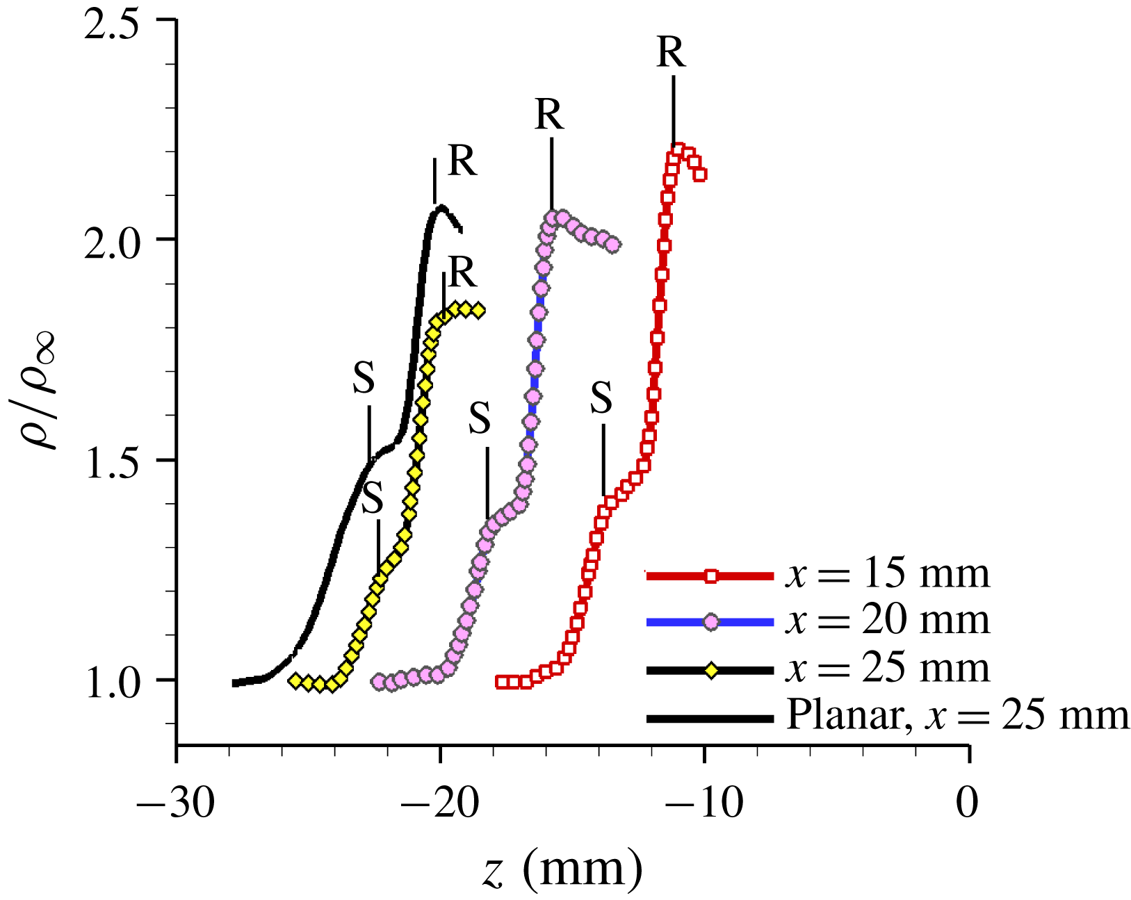
Figure 18. PLS-based density profiles at different streamwise locations at 1 mm below the triple point. ‘S’ and ‘R’ denote the locations of separation and reattachment shocks identified from r.m.s. fields.
In addition to separation shock weakening close to the triple point with downstream distance, the curvature of the separation shock due to the 3-D relief may have implications on the separated flow growth rate. To address this issue, density jumps across the separation shock along its height were determined from the PLS fields for different streamwise locations. The wall-normal locations were restricted to above the turbulent boundary layer (identified by threshold r.m.s. densities) to avoid error due to contamination of PLS signals from the viscous region. The lowest
![]() $y$
-location was chosen such that there was at least 20 pixels of very small
$y$
-location was chosen such that there was at least 20 pixels of very small
![]() $\unicode[STIX]{x1D70C}^{\prime }$
along the
$\unicode[STIX]{x1D70C}^{\prime }$
along the
![]() $z$
-axis following the separation shock before the boundary of high
$z$
-axis following the separation shock before the boundary of high
![]() $\unicode[STIX]{x1D70C}^{\prime }$
values of the shear layer was encountered.
$\unicode[STIX]{x1D70C}^{\prime }$
values of the shear layer was encountered.
Figure 19(a) shows the density jump profile along the separation shock height for the
![]() $x=20~\text{mm}$
location along with the corresponding 2-D
$x=20~\text{mm}$
location along with the corresponding 2-D
![]() $\unicode[STIX]{x1D70C}^{\prime }$
field. Each data point of the density jump at a given
$\unicode[STIX]{x1D70C}^{\prime }$
field. Each data point of the density jump at a given
![]() $y$
-location is an average over 10 rows (0.64 mm) along the
$y$
-location is an average over 10 rows (0.64 mm) along the
![]() $y$
-direction. The separation shock appears as a distinct band of high
$y$
-direction. The separation shock appears as a distinct band of high
![]() $\unicode[STIX]{x1D70C}^{\prime }$
values in the 2-D
$\unicode[STIX]{x1D70C}^{\prime }$
values in the 2-D
![]() $\unicode[STIX]{x1D70C}^{\prime }$
field in figure 19(a). It can be observed from figure 19(a) that the separation shock strength shows a sharp decrease with increasing distance from the triple point over a short distance below the triple point. Further below, the separation shock strength exhibits a plateau region that covers a fraction of the separation shock stem. This plateau is followed by another monotonic decrease in shock strength further below along the remaining length of the separation shock. Figure 19(b) shows the corresponding separation shock density jump profiles for the
$\unicode[STIX]{x1D70C}^{\prime }$
field in figure 19(a). It can be observed from figure 19(a) that the separation shock strength shows a sharp decrease with increasing distance from the triple point over a short distance below the triple point. Further below, the separation shock strength exhibits a plateau region that covers a fraction of the separation shock stem. This plateau is followed by another monotonic decrease in shock strength further below along the remaining length of the separation shock. Figure 19(b) shows the corresponding separation shock density jump profiles for the
![]() $x=15~\text{mm}$
and
$x=15~\text{mm}$
and
![]() $x=25~\text{mm}$
locations. Whereas the plateau in density ratio is very clear in the
$x=25~\text{mm}$
locations. Whereas the plateau in density ratio is very clear in the
![]() $x=25~\text{mm}$
profile, it is not identifiable at
$x=25~\text{mm}$
profile, it is not identifiable at
![]() $x=15~\text{mm}$
, possibly due to a shorter separation shock height than what could be resolved adequately. This variation of the separation shock strength along its height in fin-on-cylinder SBLI is very different from the planar SBLI (figure 19
c), where the density jumps across the separation shock height exhibit almost a constant value illustrating a constant separation shock strength.
$x=15~\text{mm}$
, possibly due to a shorter separation shock height than what could be resolved adequately. This variation of the separation shock strength along its height in fin-on-cylinder SBLI is very different from the planar SBLI (figure 19
c), where the density jumps across the separation shock height exhibit almost a constant value illustrating a constant separation shock strength.
The variation of the separation shock strength along its height in the fin-on-cylinder SBLI shows that the outer flow processed by the separation shock (above the viscous regions) is rotational, contrasting with the irrotational flow above the viscous regions of planar fin SBLI. It is hypothesized that the rotational nature of the outer flow can modulate the entrainment characteristics of the shear layer above the primary separation vortex. This can, in turn, modify the local size and strength of the primary separation vortex, similar to the separation bubble size modulations caused by shear layer entrainment variations proposed by (Piponniau et al. Reference Piponniau, Dussauge, Debieve and Dupont2009). Thus, as the shock curvature increases with downstream distance, the outer flow becomes increasingly rotational and causes strong modifications to the primary separation vortex with downstream distance, and consequently impact the separated flow growth rate. This hypothesis is supported by the steep reduction in the pressure minima between S2 and R1 with increasing downstream distance (figure 11), which suggests that the primary separation vortex strength intensifies with downstream distance.

Figure 19. PLS-based density jump at various
![]() $y$
-distances along the separation shock: (a) density ratio variation at
$y$
-distances along the separation shock: (a) density ratio variation at
![]() $x=20~\text{mm}$
along with the corresponding field that illustrates the separation shock structure; (b)
$x=20~\text{mm}$
along with the corresponding field that illustrates the separation shock structure; (b)
![]() $y$
variation of the separation shock strength at different streamwise locations; (c) corresponding density jump in planar fin SBLI at different streamwise locations.
$y$
variation of the separation shock strength at different streamwise locations; (c) corresponding density jump in planar fin SBLI at different streamwise locations.
Influence of finite fin height
Figure 18 reveals that the inviscid shock at
![]() $x=25~\text{mm}$
displays a critical difference between finite and infinite height fins – whereas the maximum strength of the inviscid shock is
$x=25~\text{mm}$
displays a critical difference between finite and infinite height fins – whereas the maximum strength of the inviscid shock is
![]() $\unicode[STIX]{x1D70C}_{2}/\unicode[STIX]{x1D70C}_{\infty }=1.9$
with the finite fin, the shock strength approaches the theoretical 2-D value (
$\unicode[STIX]{x1D70C}_{2}/\unicode[STIX]{x1D70C}_{\infty }=1.9$
with the finite fin, the shock strength approaches the theoretical 2-D value (
![]() $\unicode[STIX]{x1D70C}_{2}/\unicode[STIX]{x1D70C}_{\infty }=2.2$
) for the infinite fin case. Further comparisons of density profiles made in figure 17(b) show that the shock strength for the two fin heights was approximately the same at the location corresponding to the triple point observed from PLS images. This leads to the question, ‘how much of the SBLI modifications observed in the fin-on-cylinder configuration are due to finite fin height?’
$\unicode[STIX]{x1D70C}_{2}/\unicode[STIX]{x1D70C}_{\infty }=2.2$
) for the infinite fin case. Further comparisons of density profiles made in figure 17(b) show that the shock strength for the two fin heights was approximately the same at the location corresponding to the triple point observed from PLS images. This leads to the question, ‘how much of the SBLI modifications observed in the fin-on-cylinder configuration are due to finite fin height?’
To elucidate the finite fin height effect, SSV and PLS imaging were performed with a 50 mm tall fin at the same flow conditions as the 25 mm tall fin discussed so far. Figure 20 shows the PLS image of the shock structure generated by the 50 mm fin obtained at
![]() $x=25~\text{mm}$
, where the 25 mm fin showed significant attenuation of the inviscid shock strength (figure 17
a). It can be observed from figure 20(a) that the inviscid shock straightens out above
$x=25~\text{mm}$
, where the 25 mm fin showed significant attenuation of the inviscid shock strength (figure 17
a). It can be observed from figure 20(a) that the inviscid shock straightens out above
![]() $y=8~\text{mm}$
. In fact, the density jump values show that the density ratio across the shock between
$y=8~\text{mm}$
. In fact, the density jump values show that the density ratio across the shock between
![]() $y=8~\text{mm}$
to 30 mm is equal to the 2-D inviscid density ratio. The separation shock structure of the 50 mm tall fin retains many similarities with the 25 mm fin case in terms of having a steep curvature that wraps around the cylinder. Comparison of the density jump across the separation shock at select heights below the triple point is shown in figure 20(b). It can be observed that density jump profiles between the 50 mm and 25 mm tall fins are almost identical to one another. More importantly, there is less than 5 % difference in the density jump at the outer boundary of the turbulent boundary layer where the separation shock meets the boundary layer. These analyses show that the separation and reattachment shock structures are qualitatively and quantitatively identical between the 50 mm and 25 mm tall fins, and the boundary layer experiences almost identical separation shock strength.
$y=8~\text{mm}$
to 30 mm is equal to the 2-D inviscid density ratio. The separation shock structure of the 50 mm tall fin retains many similarities with the 25 mm fin case in terms of having a steep curvature that wraps around the cylinder. Comparison of the density jump across the separation shock at select heights below the triple point is shown in figure 20(b). It can be observed that density jump profiles between the 50 mm and 25 mm tall fins are almost identical to one another. More importantly, there is less than 5 % difference in the density jump at the outer boundary of the turbulent boundary layer where the separation shock meets the boundary layer. These analyses show that the separation and reattachment shock structures are qualitatively and quantitatively identical between the 50 mm and 25 mm tall fins, and the boundary layer experiences almost identical separation shock strength.
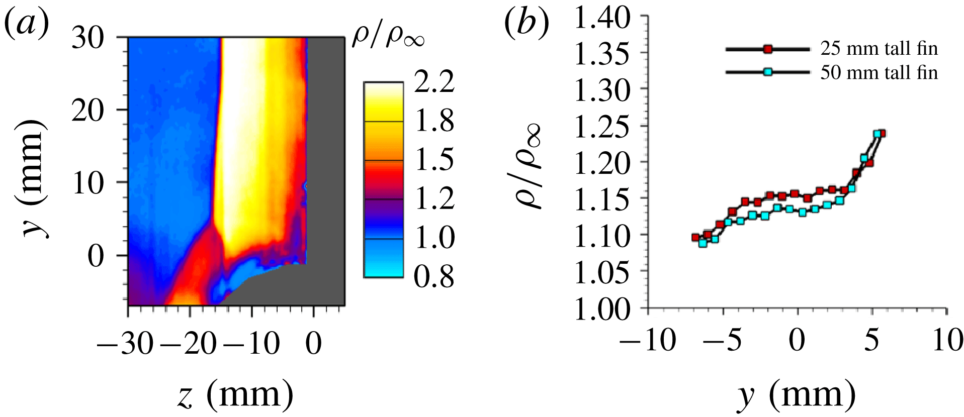
Figure 20. (a) Off-body PLS-based density field at
![]() $x=25~\text{mm}$
; and (b) comparison of the variation of density jump across the separation shock at various heights between 25 and 50 mm tall fins.
$x=25~\text{mm}$
; and (b) comparison of the variation of density jump across the separation shock at various heights between 25 and 50 mm tall fins.
Figure 21(a) shows the corresponding surface streakline visualization image and (b) the mean surface pressure field over the cylinder surface with the 50 mm tall fin-on-cylinder SBLI. It can be observed that all the qualitative features of the separation loci, which include the reduction in separated flow growth rate with streamwise distance, loss of quasi-conical symmetry of primary and secondary separation loci and near linear locus of the primary reattachment, are also present in the 50 mm tall fin case. Figure 21(c) compares the mean surface pressure profiles at different streamwise locations between the 50 mm and 25 mm tall fins to make a quantitative comparison. The locations of the separation and reattachment are marked in the figure (circle: primary separation, delta: secondary separation, star: primary reattachment). It can be observed that the pressure profiles are quantitatively agreeable between the two configurations at all streamwise locations. Discrepancies can be seen in the pressure at reattachment, which are attributed to slight differences in stagnation conditions during testing. Furthermore, the locations of the primary and secondary separations and primary reattachment are all in quantitative agreement between the two fin heights within the measurement uncertainty. The remarkable quantitative agreements in the pressure fields and separation/reattachment loci evolution shows that the finite height of the fin for the cases considered in this work makes only negligible impact to the separated flow topology and shock structure, and does not alter the overall findings.

Figure 21. Delineation of surface features of the SBLI generated by a 50 mm tall fin-on-cylinder: (a) surface streakline visualization image; (b) mean wall pressure field; and (c) comparison of free-stream-normalized mean wall pressure profiles for the 25 mm and 50 tall fins.
Comments on downstream evolution of fin-on-cylinder SBLI versus planar fin SBLI
While the present study focused on limited cylinder diameters and the streamwise measurement locations spanned just until where the separation shock skipped the cylinder surface, the findings on the separated flow growth rate can be extended to more general situations by noting some of the fundamental differences in the downstream separated flow evolution between the fin-on-cylinder and planar SBLI. Figure 22 considers the SBLI generated by an infinitely tall fin placed on a flat plate vs on the cylinder with diameter
![]() $D$
. For simplicity, the fin is considered to be sufficiently long so that the expansion fans from its elbow are neglected. Figure 22 illustrates the qualitative loci of the separation shock foot, inviscid shock, and reattachment locus for both planar and fin-on-cylinder SBLI. In the planar fin SBLI situation, the separation shock has the same strength and extends across the entire streamwise distance considered. Hence, the boundary layer that is located farther away in the spanwise direction is processed by the separation shock at more downstream streamwise locations. This provides a continuous supply of new vorticity to the primary separation vortex, which sustains its strength with downstream distance and results in the continuous growth of the separated flow, as illustrated by the orange contour in figure 22(a). In contrast, the PLS imaging showed that fin-on-cylinder separation shock impacts the incoming boundary layer only until where the separation shock foot location meets the cylinder surface at
$D$
. For simplicity, the fin is considered to be sufficiently long so that the expansion fans from its elbow are neglected. Figure 22 illustrates the qualitative loci of the separation shock foot, inviscid shock, and reattachment locus for both planar and fin-on-cylinder SBLI. In the planar fin SBLI situation, the separation shock has the same strength and extends across the entire streamwise distance considered. Hence, the boundary layer that is located farther away in the spanwise direction is processed by the separation shock at more downstream streamwise locations. This provides a continuous supply of new vorticity to the primary separation vortex, which sustains its strength with downstream distance and results in the continuous growth of the separated flow, as illustrated by the orange contour in figure 22(a). In contrast, the PLS imaging showed that fin-on-cylinder separation shock impacts the incoming boundary layer only until where the separation shock foot location meets the cylinder surface at
![]() $\unicode[STIX]{x1D703}=90^{\circ }$
. Beyond this limiting location, PLS images at
$\unicode[STIX]{x1D703}=90^{\circ }$
. Beyond this limiting location, PLS images at
![]() $x=20~\text{mm}$
and 25 mm of figures 13 and 15 shows that the separation shock foot runs almost parallel to the cylinder surface without engulfing further boundary layer into the separated flow. Thus, the separated flow of fin-on-cylinder SBLI does not have a continuous supply of vorticity from the incoming boundary layer to sustain its growth rate beyond the limiting location where the separation shock foot meets the cylinder at
$x=20~\text{mm}$
and 25 mm of figures 13 and 15 shows that the separation shock foot runs almost parallel to the cylinder surface without engulfing further boundary layer into the separated flow. Thus, the separated flow of fin-on-cylinder SBLI does not have a continuous supply of vorticity from the incoming boundary layer to sustain its growth rate beyond the limiting location where the separation shock foot meets the cylinder at
![]() $\unicode[STIX]{x1D703}=90^{\circ }$
. As a result, the separated vortex strength of fin-on-cylinder SBLI is expected to dissipate, and the separation is expected to continuously shrink and eventually close after certain downstream distance, as illustrated in figure 22(b). This eventual closure of separation in fin-on-cylinder SBLI contrasts with the planar fin SBLI that has an open separation with sustained strength.
$\unicode[STIX]{x1D703}=90^{\circ }$
. As a result, the separated vortex strength of fin-on-cylinder SBLI is expected to dissipate, and the separation is expected to continuously shrink and eventually close after certain downstream distance, as illustrated in figure 22(b). This eventual closure of separation in fin-on-cylinder SBLI contrasts with the planar fin SBLI that has an open separation with sustained strength.

Figure 22. Top view schematics of the separated flow in planar fin SBLI versus fin-on-cylinder SBLI to illustrate the separated flow shrinkage downstream of the limiting boundary layer in fin-on-cylinder SBLI: (a) planar fin SBLI; and (b) fin-on-cylinder SBLI. The shaded orange region portrays the separated flow in both figures.
Considering the limiting streamwise location until which the boundary layer can contribute to the separation vortex strength occurs where the separation shock foot meets the cylinder at
![]() $\unicode[STIX]{x1D703}=90^{\circ }$
, the parameters that determine the streamwise location where this occurs will influence the streamwise separation size to the first order. These include the inviscid shock angle, which correlates very well with the separation shock foot locus, and the cylinder diameter. To a good approximation, the streamwise location of the limiting boundary layer can be determined by locating where the portion of the inviscid shock that is not influenced by the cylinder curvature reaches the cylinder edge. The location can be expressed as
$\unicode[STIX]{x1D703}=90^{\circ }$
, the parameters that determine the streamwise location where this occurs will influence the streamwise separation size to the first order. These include the inviscid shock angle, which correlates very well with the separation shock foot locus, and the cylinder diameter. To a good approximation, the streamwise location of the limiting boundary layer can be determined by locating where the portion of the inviscid shock that is not influenced by the cylinder curvature reaches the cylinder edge. The location can be expressed as
![]() $x_{limit}=k_{s}\times D/(2\times \tan (\unicode[STIX]{x1D6FD}_{s}))$
, where
$x_{limit}=k_{s}\times D/(2\times \tan (\unicode[STIX]{x1D6FD}_{s}))$
, where
![]() $\unicode[STIX]{x1D6FD}_{s}$
is the inviscid shock angle,
$\unicode[STIX]{x1D6FD}_{s}$
is the inviscid shock angle,
![]() $D$
is the cylinder diameter and
$D$
is the cylinder diameter and
![]() $k_{s}$
is a parameter that corrects for the difference in locations where the inviscid shock and separation shock foot reach the cylinder edge. Thus, a smaller diameter cylinder, larger fin angle or smaller Mach number are expected to have the limiting boundary layer at a shorter streamwise distance, which would lead to a smaller streamwise separation size as a first approximation. Certainly, the dissipation of the separation vortex strength does depend on the geometry and flow properties, which are also expected to influence the size of the separated flow and its closure.
$k_{s}$
is a parameter that corrects for the difference in locations where the inviscid shock and separation shock foot reach the cylinder edge. Thus, a smaller diameter cylinder, larger fin angle or smaller Mach number are expected to have the limiting boundary layer at a shorter streamwise distance, which would lead to a smaller streamwise separation size as a first approximation. Certainly, the dissipation of the separation vortex strength does depend on the geometry and flow properties, which are also expected to influence the size of the separated flow and its closure.
Influence of wind tunnel boundary layer on separation topology
Finally, considering the cylinder edges of the model (
![]() $\unicode[STIX]{x1D703}=\pm 90^{\circ }$
) were removed from the wind tunnel walls by only twice the tunnel boundary layer thickness, the potential interference from the wind tunnel boundary layers towards the separation topology was also examined using RANS simulations. RANS simulations were carried out by employing identical fin and cylinder geometries and inflow boundary layer profiles, but using different boundary conditions. A symmetry boundary condition was used along the edges of the cylinder surface (
$\unicode[STIX]{x1D703}=\pm 90^{\circ }$
) were removed from the wind tunnel walls by only twice the tunnel boundary layer thickness, the potential interference from the wind tunnel boundary layers towards the separation topology was also examined using RANS simulations. RANS simulations were carried out by employing identical fin and cylinder geometries and inflow boundary layer profiles, but using different boundary conditions. A symmetry boundary condition was used along the edges of the cylinder surface (
![]() $\unicode[STIX]{x1D703}=\pm 90^{\circ }$
) to emulate the effect of wind tunnel wall present at the cylinder edges, and an outflow boundary condition was imposed at the edges to simulate a condition where the wind tunnel wall was absent. It should be noted that the intent of these simulations is not to have the best quantitative agreement of the experimental SBLI, but rather to learn if there are gross changes in the separated flow field due to the presence of wind tunnel walls. With this philosophy, the separated flow streaklines were compared for the cases with and without wind tunnel walls. Figure 23 shows the comparison of the surface streakline patterns of the SBLI generated with symmetry boundary condition (figure 23
a) and outflow boundary condition (figure 23
b). It can be observed that the separated flow retains the same topology between the two cases. A quantitative comparison of the separation/reattachment features, which included the different loci and shock structures (not shown) are also identical between the two cases. This virtual identity between the two cases provides compelling evidence that the any interference from the wind tunnel walls make only negligible contribution to the SBLI structure and the separated flow topology.
$\unicode[STIX]{x1D703}=\pm 90^{\circ }$
) to emulate the effect of wind tunnel wall present at the cylinder edges, and an outflow boundary condition was imposed at the edges to simulate a condition where the wind tunnel wall was absent. It should be noted that the intent of these simulations is not to have the best quantitative agreement of the experimental SBLI, but rather to learn if there are gross changes in the separated flow field due to the presence of wind tunnel walls. With this philosophy, the separated flow streaklines were compared for the cases with and without wind tunnel walls. Figure 23 shows the comparison of the surface streakline patterns of the SBLI generated with symmetry boundary condition (figure 23
a) and outflow boundary condition (figure 23
b). It can be observed that the separated flow retains the same topology between the two cases. A quantitative comparison of the separation/reattachment features, which included the different loci and shock structures (not shown) are also identical between the two cases. This virtual identity between the two cases provides compelling evidence that the any interference from the wind tunnel walls make only negligible contribution to the SBLI structure and the separated flow topology.
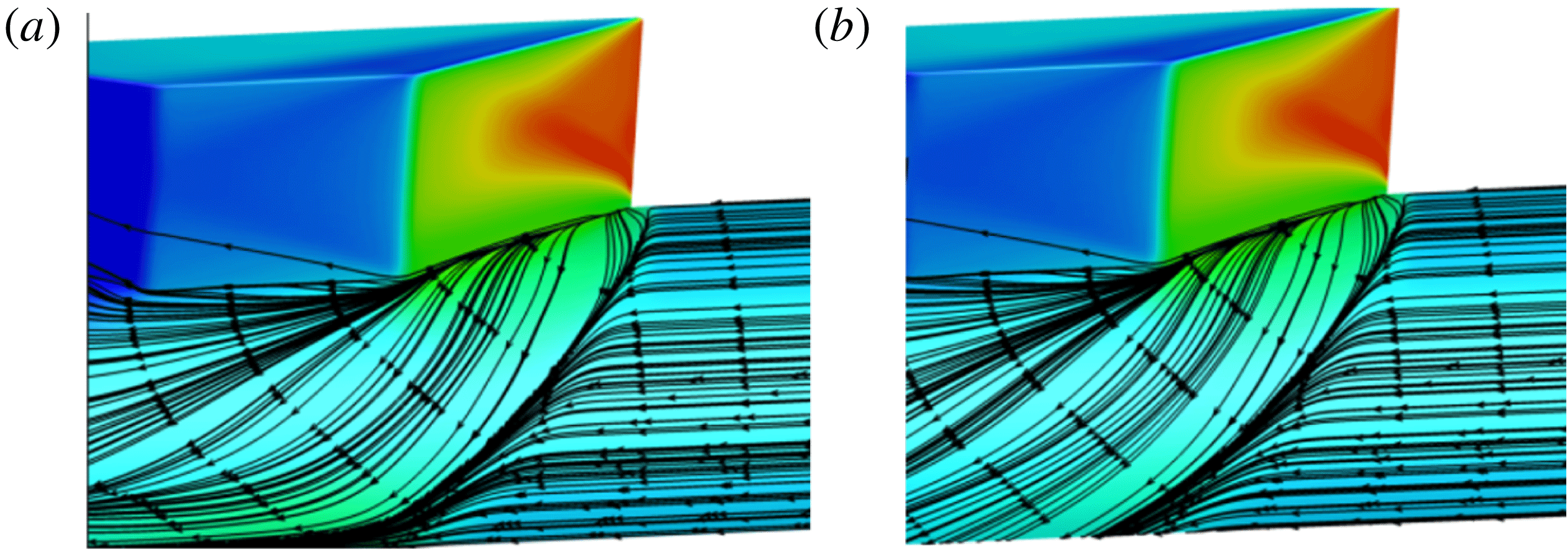
Figure 23. Surface streakline patterns obtained from RANS simulations of the fin-on-cylinder SBLI flow field: (a) with wind tunnel boundary layer interference; and (b) without wind tunnel interference.
6 Conclusions
Complementary experimental and computational investigations were performed to unravel the flow field associated with the SBLI generated by a sharp fin mounted on a half-cylinder model. The prime feature of this fin-on-cylinder SBLI configuration is the 3-D relief offered by the cylindrical surface, which was hypothesized to fundamentally alter the structure of the SBLI unit. The main objectives of the investigations were to visualize and quantify the mean features of the fin-on-cylinder SBLI and determine the mechanisms that drive the separation features. First, detailed streakline visualizations over a variety of fin angles, inflow Mach number and cylinder diameters showed that the separation regimes of the fin-on-cylinder SBLI were essentially identical to planar fin SBLI. Further investigations into the separation/reattachment loci of the fin-on-cylinder from the streakline images showed that the separated flow growth rate reduced with downstream distance, a stark contrast to planar SBLI where the growth rate is constant. Furthermore, the direct comparison between the fin-on-cylinder SBLI and corresponding planar fin SBLI at identical inflow Mach numbers showed that the separation size is considerably smaller for the fin-on-cylinder SBLI configuration. The curved nature of the SBLI surface features are also reflected in wall pressure fields. Examination of the wall pressures beneath the primary and secondary separation and reattachment locations show that the wall pressure values decreased by varying amounts with downstream distance. This contrasts with planar fin SBLI where the wall pressures at separation and reattachment locations remained constant with downstream distance. Furthermore, the wall pressure profiles also strongly suggest that the primary separation vortex gain its strength with downstream distance, which contrasts with the planar fin SBLI where the primary separation vortex evolves with near constant strength with streamwise distance. Subsequent visualization of the shock structure using planar laser scattering showed that whereas the overall shock unit had large similarities with planar fin SBLI, the separation and inviscid shock exhibited a large curvature with increasing downstream distance from the fin leading edge, and the separation shock wrapped around the cylinder surface with downstream distance without the shock foot touching the cylinder surface.
Euler and RANS simulations were performed in conjunction with PLS-based density field imaging to learn the mechanisms that are responsible for the smaller separation size and decreased separated flow growth rate in the fin-on-cylinder SBLI. It was found that the presence of 3-D relief weakens the inviscid shock in the region close to the cylinder surface, and the shock weakening propagates higher into the inviscid shock with downstream distance. The increasingly weaker inviscid shock strength near the triple point with downstream distance feeds into the separation shock, and the strength of the separation shock when it interacts with the boundary layer progressively weakens with downstream distance, which causes a later onset of primary separation compared to planar fin SBLI. The close agreement between the separation onset prediction based on free interaction theory using inviscid shock strength at a given downstream location and experimental values corroborate the dominant influence of the weakening inviscid shock strength towards determining primary separation onset. Further examination of the flow processed by the curved separation shock showed that the outer flow above the viscous separated flows is expected to be rotational due to the variation of the separation shock strength along its height and streamwise distance. The rotational nature of the outer flow can modulate the entrainment characteristics of the shear layer above the separation vortex thereby impacting its size and downstream evolutions. The observations on the fin-on-cylinder SBLI were found to not depend on the fin height for the range that were used in this work, and the influence from the wind tunnel boundary layers on the separation features is computed to be marginal. Overall, this study provides one of the first comprehensive investigations into the impacts of 3-D relief effects on a fin-on-cylinder SBLI and the mechanisms that influence the mean SBLI structure.
The unsteadiness in the flow would be of certain interest, and a topic for future work when the techniques required for such measurements are properly established. Concerted experimental (high speed PIV, unsteady pressure imaging, etc.) and computational (LES) approaches to address the unsteady aspects of the SBLI are being undertaken. However, these approaches are still being validated against the literature and are not mature enough to find application in the current flow field.
Acknowledgement
Funding for this investigation has been provided by the Army Research Office under grant W911NF-16-1-0072.


