Introduction
Positron emission tomography (PET) is an exciting and powerful medical imaging technique that has revolutionized cancer treatment. Timely, rapid diagnosis and prevention of disease progression are unique features of this method. PET also helped physicians to diagnose the stage of disease and its rate of progress by creating extremely high-resolution 3D images. In this imaging method, radioactive isotopes that emit positron are used. The common isotopes in PET include: (a) Carbon 11 with a half-life of 20 min; (b) nitrogen 13 (N-13) with a half-life of 10 min; (c) O-15 with a half-life of 2 min and (d) fluorine 18 with a half-life of 110 min. Carbon, nitrogen, and oxygen are found in all organs and tissues of the body so, they are a very good candidate for PET imaging. The cyclotron accelerators are usually used to produce mentioned isotopes. Due to the short half-life of these isotopes, their production process should be in the consumption time interval. Because of the high cost, complexity of construction, maintenance, and repair of cyclotron accelerators many hospitals are not able to use the PET technique for imaging. All of the above limitations have led to a lot of focus on designing and manufacturing of inexpensive and user-friendly PET imaging devices that are suitable for small and large therapeutic centers. Very simple design along with low cost of manufacturing can make plasma focus devices as a good candidate that can produce high-energy ions, radioisotope, and dense plasma in the near future (Roshan et al., Reference Roshan, Springham, Rawat and Lee2010; Auluck, Reference Auluck2014; Sadeghi et al., Reference Sadeghi, Amrollahi, Zare and Fazelpour2017a). Plasma focus devices can also produce neutrons, soft X, and hard X (Beg et al., Reference Beg, Ross and Dangor1997; Mohammadi et al., Reference Mohammadi, Verma, Sobhanian, Wong, Lee, Springham, Tan, Lee and Rawat2007; Verma et al., Reference Verma, Roshan, Malik, Lee, Lee, Springham, Tan, Krishnan and Rawat2008). Until now, various plasma focus devices with the energy range of 0.1–1 MJ have been designed and manufactured (Soto et al., Reference Soto, Pavez, Tarifeno, Moreno and Veloso2010; Sadeghi et al., Reference Sadeghi, Habibi and Ghasemi2017b, Reference Sadeghi, Roshan, Fazelpour and Zare2017c). Recently, production of N-13 by plasma focus devices has been highly regarded by researchers. Kakavandi et al., (Reference Kakavandi, Roshan and Habibi2016) have investigated the production of N-13 due to the collision of energetic deuterium ions with graphite target. They have investigated the production of N-13 in various plasma focus devices empirically and theoretically. Akel et al. (Reference Akel, Alsheikh Salo, Ismael, Saw and Lee2014) calculated energy spectrum and the number of D ions produced in plasma focus devices with a variety of energy range using the Li code. Also, they have calculated the number of 1 MeV ions which have the capability of producing N-13 during collision with graphite targets. Eventually, the activity and production of N-13 have been calculated and reported for a wide range of plasma focus devices from a few hundred J to several hundred KJ. Roshan et al. (Reference Roshan, Springham, Rawat and Lee2010) showed that the energy distribution of energetic deuterium ions in plasma focus device does not follow the power law contrary to the articles. They obtained deuterons spectrum produced in the NX2 plasma focus device using magnetic spectrometry. Finally, they calculated the number of neutrons and N-13 generated in this device. Roshan et al. (Reference Roshan, Springham, Rawat and Lee2010) have studied the production of N-13 using a 1.7 kJ plasma focus device. They achieved activity of 40 kBq and 10 MBq by bombardment of a graphite target using energetic deuterium ions with a frequency of 1 and 16 Hz during 30 s, respectively. Many literatures investigated the production of N-13 in the plasma focus devices. But so far, none of the experiments on various plasma focus devices have been achieved enough activity for medical applications. A very little price ($10–20 000) of a plasma focus device against the high cost of cyclotron accelerators ($1–2 million) has encouraged the scientists to perform many experiments on the production of N-13 using plasma focus device. In this paper, we will examine and implement a novel and effective idea to produce N-13 with the least cost using plasma focus device for medical purposes. The objectives of this paper are:
1. Presents a new idea to build a cheap, simple, and operative source to produce N-13
2. Design, simulation, and feasibility of ideas using MCNPX Code and COMSOL Simulation Software
3. Increase the production rate of N-13 in optimized plasma focus devices
Theory and calculation
Many studies have been carried out on plasma focus devices to produce N-13. Roshan et al. (Reference Roshan, Springham, Rawat and Lee2010) showed that a 1.7 kJ plasma focus device with a frequency of 16 Hz can be achieved to 10 MBq activity during 30 s. The result is achieved while only 0.02% of the produced ions in this device have enough energy to produce N-13 due to collision with graphite target. Equation (1) shows the total number of N-13 due to the collision of deuterium ions (Akel et al., Reference Akel, Alsheikh Salo, Ismael, Saw and Lee2014; Kakavandi et al., Reference Kakavandi, Roshan and Habibi2016).
 $$N_{13N} = {\rm \xi} N_t\displaystyle{{1-m} \over {E_{{\rm max}}^{1-m} -E_{{\rm min}}^{1-m}}} \mathop \int \limits_{E_{{\rm min}}}^{E_{{\rm max}}} E^{-m}\left( {\mathop \int \limits_{E_{th}}^E n\sigma \lpar E \rpar {\left( {\displaystyle{{dE} \over {dx}}} \right)}^{-1}dE} \right)dE$$
where (dE)/(dx) is the stopping power calculated using SRIM code.  $\int_{E_{th}}^E {n\sigma \lpar E \rpar {\lpar {(dE/(dx))} \rpar }^{-1}dE} $ is the probability of deuterium reaction with graphite target during passing through target, n is the density of graphite target, and ξ is a fraction of the deuterium ions that hit the graphite target. Activity is obtained according to Akel et al. (Reference Akel, Alsheikh Salo, Ismael, Saw and Lee2014):
 $$A = N_{13N}f\lpar {1-e^{(\ln 2)/(T_{1/2})t}} \rpar \; $$
f is the operating frequency of the plasma focus device and t is the operating time of the plasma focus device. It is evident from Equations (1) and (2) that the level of activity depends on two key parameters: The number of energetic ions and the cross-section of the reaction. The cross-section of the reaction of the D ions with graphite target reaches to its maximum value (240 mbarn) at 2.3 MeV.
Only a very small fraction of the produced ions in plasma focus device have enough energy to react with the graphite to produce N-13. So, by designing an ion acceleration mechanism the cross-section of reaction increases in addition to increasing the number of energetic ions. In this paper, the number of energetic ions has been increased significantly using electromagnetic waves (EMWs). EMWs propagate in open space with transverse electromagnetism (TEM) mode. In this case, the electric and magnetic fields of the wave are perpendicular to each other, in addition to being perpendicular to the wave propagation direction. But EMWs will have unique characteristics using limitation of them by conducting walls (waveguides) which depend on the structure and dimensional characteristics of the waveguide. Waveguides are divided into two categories: Transverse electric (TE mode, no electric component in the direction of propagation) and transverse magnetic (TM mode, no magnetic component in the direction of propagation).
Researches have shown that for TM010 mode in the cylindrical waveguides the electric field reaches to its maximum value along the waveguide axis. The electric field equations for cylindrical waveguide in TM011 mode are shown in Equations (3)–(5) (Balanis, Reference Balanis1989; Sullivan and Micci, Reference Sullivan and Micci1993; Bilén et al., Reference Bilén, Valentino, Micci and Clemens2005).
 $$E_z = A_{01}J_0\left[ {\displaystyle{{\chi_{01}} \over a}{\rm \rho}} \right]\cos \left( {\displaystyle{\pi \over h}} \right)$$
 $$E_{\rm \rho} = A_{01}\displaystyle{{\pi a} \over {\chi _{01}h}}J_1\left[ {\displaystyle{{\chi_{01}} \over a}{\rm \rho}} \right]\sin \left( {\displaystyle{\pi \over h}} \right)\; $$
 $$E_{\rm \varphi} = 0\; $$
where J 0 is the Bessel function of the first type of zeroth order. χ 01 is the first zero of this Bessel function.
The relationship between the dimensions of the cavity and the frequency of the wave is obtained from Equation (6).
 $$f_{{\rm T}{\rm M}_{011}} = \displaystyle{1 \over {2\pi \sqrt {{\rm \mu} {\rm \varepsilon}}}} \sqrt {{\left( {\displaystyle{{\chi_{01}} \over a}} \right)}^2 + {\left( {\displaystyle{{\rm \pi} \over h}} \right)}^2} $$
According to Equations (3)–(5), the electric field of the wave along the cavity axis (ρ = 0) will have only one component along the cavity axis (Z-axis), and this strong field will accelerate the ions along the cavity axis.
Design and simulation
A large number of produced ions in plasma focus device with a wide energy range (a few KeV to a few MeV) move to the upward direction after the acceleration phase. The motion of these ions is cone shaped so that the tip angle of the cone is close to 25° (Sadeghi et al., Reference Sadeghi, Roshan, Fazelpour and Zare2017c). In a plasma focus device, only 0.02% of the generated ions have more than 1 MeV energy (Akel et al., Reference Akel, Alsheikh Salo, Ismael, Saw and Lee2014). In this paper, using a new idea we have tried to find a solution to increase the energy of deuterium ions to produce N-13. To achieve this, a series of magnetic lenses has been used to focus and guide the ions (Sadeghi et al., Reference Sadeghi, Amrollahi, Zare and Fazelpour2017a). To increase the ion energy, a small linear accelerator has been designed using a TM010 waveguide. The accelerator waveguide is also designed and optimized to have the highest impedance matching and maximum power transmission. Eventually, low-energy ions that are transmitted by magnetic lenses accelerate in the waveguide electric field and their energy increases significantly. The collision of these energetic ions with graphite target produce N-13. An overall view of the device is shown in Figure 1.
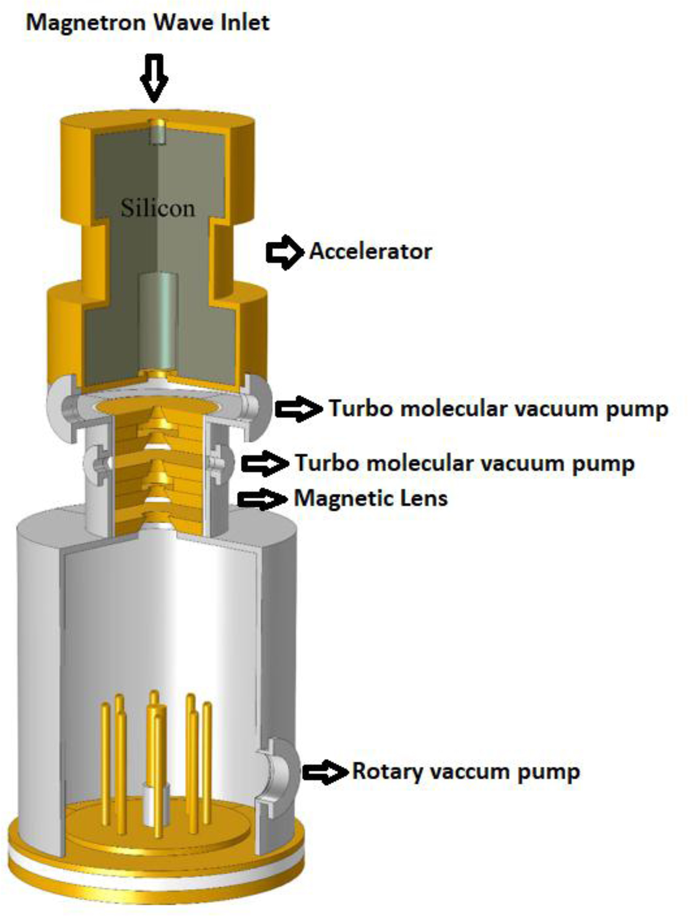
Fig. 1. A general view of the device, including plasma focus device, magnetic lenses, and accelerator.
Some geometric and electrical characteristics of the plasma focus device shown in Figure 1 are presented in Table 1.
Table 1. Design parameters

According to Figure 1, two pumps have been used consisting of a rotary pump for the plasma focus device and a turbo-molecular pump for the accelerator chamber. In addition to focusing and directing the ions towards the accelerator, magnetic lenses are the main cause of the pressure difference between the plasma focus chamber and the accelerator chamber (Sadeghi et al., Reference Sadeghi, Amrollahi, Zare and Fazelpour2017a). Also, the magnetic field effect caused by the lens inside the plasma focus chamber and the anode tip should be negligible. Magnetic field of the lenses at different points, gas pressure at different points, pressure changes along the axis of the device, and the magnetic field changes along the axis of the device are shown in Figure 2a–2d, respectively.
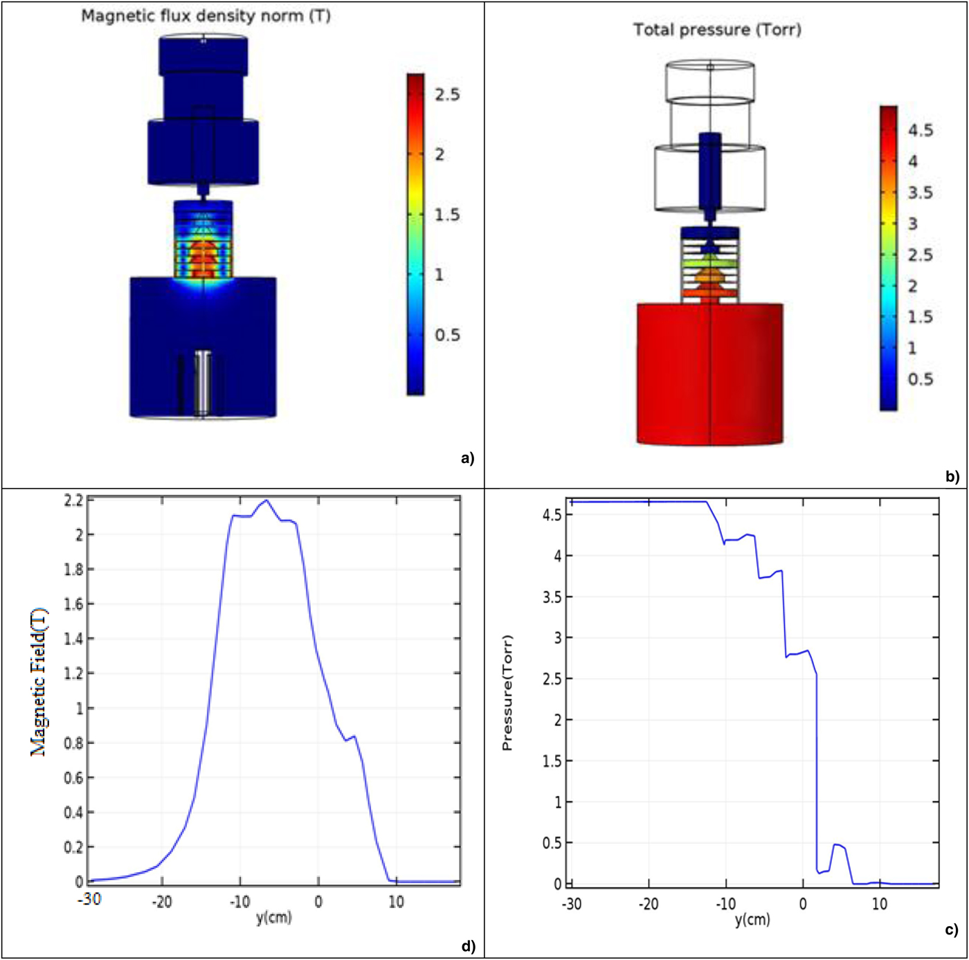
Fig. 2. (a) The magnetic field of the lenses at different points of plasma focus device and accelerator chamber (d) The magnetic field of the lenses along the axis of the device Figure 2: (b) Pressure at different points of the plasma focus device and accelerator (c) Pressure along the axis of the device.
According to Figure 2a and 2d, the magnetic field of magnetic lenses is very weak near the anode (−30 cm). Also, according to Figure 2b and 2c, the gas pressure is around 4.5 and 10−6 torr inside the plasma focus chamber and accelerator chamber, respectively. Therefore, the mean free space for collisions between the gas atoms and ions is very large and collision probability between ions and gas atoms is very small within the accelerator. The electric field of the EMW at various points of the device and the electric field of the wave inside the waveguide (accelerator) are shown in Figure 3b and 3a, respectively. Figure 3c indicates the magnitude of the electric field of the wave inside the cylindrical waveguide before optimization.

Fig. 3. (a) Electric field of electromagnetic wave at different points of the device (b) Electric field of wave in the waveguide with matching impedance (c) Electric wave field inside the waveguide without matching impedance (d) Different parts of the accelerator.
Figure 3d shows the different parts of the designed accelerator, a TM010 cylindrical waveguide has been in this accelerator. In this type of waveguide, the electric field is in the waveguide axis direction, and the magnetic field is in the polar direction.
To transmit maximum power and avoid wave reflection in a waveguide, it is necessary to create maximum impedance matching between the wave and the waveguide using the precise design of the waveguide. Power transmission in a typical waveguide is only 30% of the total power of the wave source according to Figure 3b and 3c. Figure 3d shows an optimized waveguide that transmits the maximum source power due to impedance matching with the wave source. Table 2 presents the geometric characteristics and materials used in the design and simulation of the accelerator (waveguide).
Table 2. Structural characteristics of accelerator components

The ion number in plasma focus device is of the order of 1015–1018 (Lee and Saw, Reference Lee and Saw2012; Akel et al., Reference Akel, Alsheikh Salo, Ismael, Saw and Lee2014), but only a small fraction of these ions during collision with graphite have enough energy to produce N-13. In this paper, we tried to simulate a new device (Characteristics of each part of the device are listed in Tables 1 and 2.) using COMSOL software to produce N-13, which in addition to its very small cost, is easy to design and repair compared to cyclotron accelerators. All cross sections of the elastic scattering, non-elastic scattering, ionization, excitation, recombination, and neutralization for collision of ions with neutral gas atoms from 0.1 to 10 MeV have been specified and entered accurately in the simulation performed using COMSOL software. Eventually, more than 1012–1014 ions with the energy ranging from a few eV to a few MeV enter to the magnetic lens. But magnetic lenses will prevent the transition of low-energy ions like a magnetic mirror. Calculations and simulations show that the minimum required ions energy to pass through magnetic lenses should be more than 100 keV (Sadeghi et al., Reference Sadeghi, Amrollahi, Zare and Fazelpour2017a).
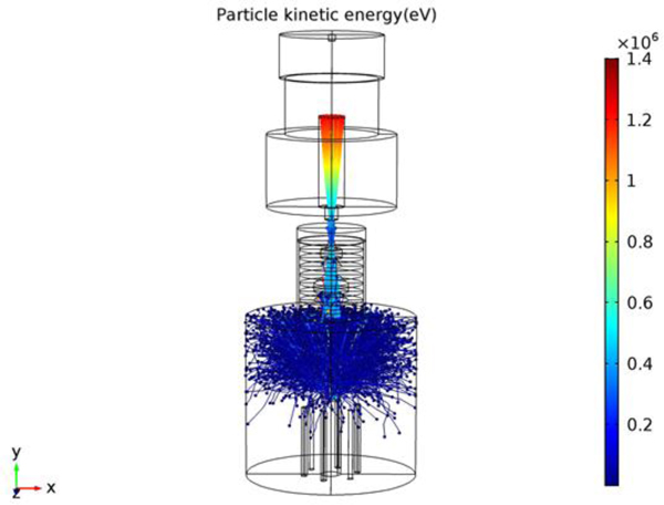
These ions are driven towards the accelerator, where they accelerate to an average of 1.2–1.5 MeV. Finally, the ions that accelerate inside the accelerator collide with a graphite target and N-13 will be produced. The path of motion and energy of particles inside the plasma focus chamber and accelerator and the collision of particles with graphite are shown in Figure 4.

Fig. 4. Moving direction and energy of particles inside plasma focus and accelerator chamber.
Result and discussion
A novel idea is presented in this paper to design, simulation, and to test the feasibility of making a machine in order to produce N-13 at a much lower cost than conventional medical applications. Generally, 1015–1018 (Total number of ions produced) ions are produced in plasma focus devices with energies of several hundred J to several hundred kJ out of which <1% of them have an energy of more than 500 keV (Lee and Saw, Reference Lee and Saw2012: Akel et al., Reference Akel, Alsheikh Salo, Ismael, Saw and Lee2014). Therefore, plasma focus device in normal ways cannot produce enough N-13 for medical purposes. Nitrogen-13 production rate for 16 plasma focus devices with different energies in two optimal and normal modes using MCNPX code and COMSOL software is presented in Table 2.
Our calculations and simulations show that 1012–1014 ions pass through the magnetic lens (Fig. 4) and then they enter the accelerator chamber. The energy of ions reaches an average of 1.2–1.5 MeV, and ultimately they collide with the graphitic target.
The results from COMSOL software and MCNPX code (Table 3) show that using the designed accelerator the activity will increase significantly. The activity diagrams are shown in both normal and optimized modes in Figure 5.
Table 3. Radioactivity in the absence (A) and presence (A*) of accelerator

A* = optimum Radioactivity.
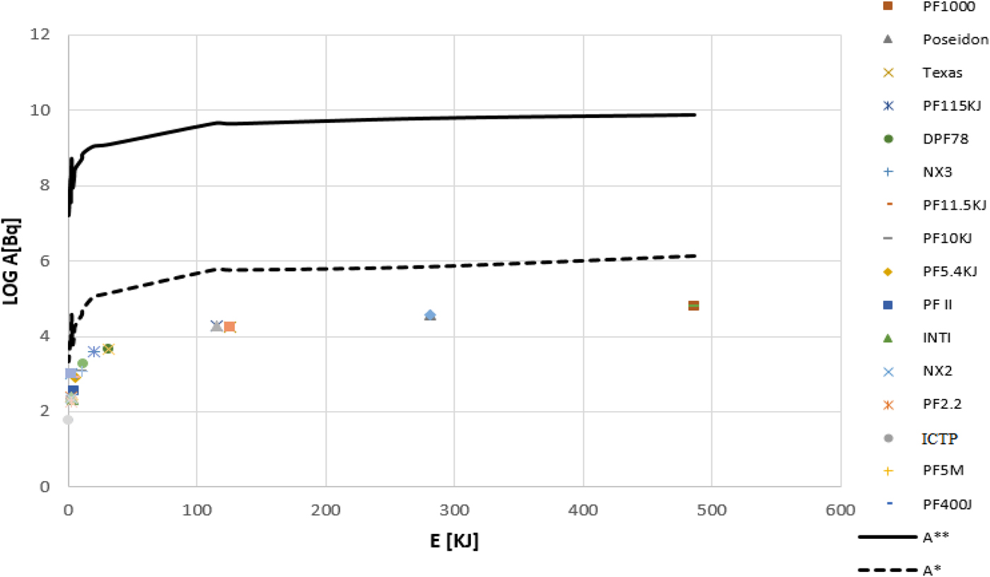
Fig. 5. Variation of activity versus energy for both normal and optimized modes.
The required activity for PET imaging is usually between 0.368 and 0.736 GBq (Akel et al., Reference Akel, Alsheikh Salo, Ismael, Saw and Lee2014). According to Table 2, about 9 plasma focus devices have the capability to produce enough activity for medical purposes, but it is important to note that the activities listed in Table 2 are merely derived from Li theory (Li code), but the activity of these devices is significantly larger during the experiments.
Conclusion
Design and simulation of a device with the capability of producing N-13 with a very low cost for medical purposes was presented in this paper. We implemented ideas for 16 focus plasma devices. The feasibility of the idea was investigated using COMSOL software and MCNPX code and finally, the following results were obtained:
1. Using magnetic lens with special geometry resulted in the significant pressure difference between plasma focus and accelerator chamber in addition to directing the ions into the accelerator chamber. The gas pressure of the plasma focus was 4.5 torr and that of the accelerator chamber was around 10−6 torr. Therefore, the mean free path was very large and the probability of collision between ions and gas atoms was very small inside the accelerator.
2. By optimization and very exact matching of the impedance in a TM010 waveguide, an accelerator which its power transfer efficiency was 9 times the normal state was designed. Optimization resulted in the creation of an efficient accelerator for increasing the ion energy and, consequently, increasing the number of N-13. 1015–1018 ions were produced in plasma focus devices with energies of several hundred J to several hundred KJ, respectively, out of which <1% of them had an energy of 500 keV and more.
3. Calculations and simulations (the results) showed that around 1012–1014 ions passed through the magnetic lens and entered the accelerator chamber and their energy reached an average of 1.2–1.5 MeV.
4. From theoretical and empirical results in various papers, it can be concluded that even the largest plasma focus devices cannot produce enough N-13 for medical purposes. Using the accelerator designed in this paper as a supplement to plasma focus devices, it was shown that we can achieve enough activity for medical purposes. By evaluating 16 plasma focus devices with the energy ranging from 400 J to 500 kJ, the activity in optimum condition was 0.016–7.71 GBq. Also, due to the fact that the amount of activity for medical purposes is 0.368–0.736 GBq of, 9 plasma focus devices have the capability of acquiring this activity.