Introduction
Microstrip bandpass filter (BPF) plays a significant role in the RF front ends. With the increasing development of multi-service wireless communication networks, quad-band BPF with high performance has garnered a great deal of attention and various design methods have been reported. The most direct approach is combining several resonators with common input/output ports to achieve a quad-band BPF, which suffers from a relatively large circuit area. For example, in [Reference Liu, Guo, Wei, Ma, Zhao, Xing and Wu1], a quad-band BPF is achieved by cascading two dual-band BPFs together with a single metallic via-holed feed line. In [Reference Zhang, Gao and Zhang2], a short-end stub-loaded resonator is used to yield the third passband, and the other multi-stub-loaded resonators operate at the first, second, and fourth passband. In [Reference Wu, Qiu and Lin3], using two stub-loaded nested dual-band loop resonators realizes quad-band BPF. In [Reference Yan, Tang and Wang4], two sets of short stub loaded e-shape resonators are utilized to design a quad-band BPF. The second approach is adopting double-layered structure to reduce the overall circuit size of quad-band BPF, which increases the fabrication complexity [Reference Wu and Chiu5]. The third design category is utilizing a single simple resonator which can obtain a compact filter size. A quad-band BPF based on a novel stub-loaded stepped impedance resonator is designed in [Reference Wei, Huang, Li and Shi6]. Nevertheless, the bandwidths of the quad-band BPF are not controllable independently. There is one transmission zero (TZ) on two sides of each passband, so both lower and upper stopband do not simultaneously suppress very well.
In comparison to aforementioned methods, quad-band BPFs [Reference Xu, Miao, Cui, Ji and Wu7–Reference Liu, Wang, Wang, Li, Zhao and Guan9] based on quad-mode resonators (QMRs) are usually convenient to tune various parameters. A QMR is proposed by embedding short-circuit stub into the conventional two-side open-circuit resonator in [Reference Xu, Miao, Cui, Ji and Wu7], but the bandwidths cannot be controlled independently and the passband selectivity needs to be improved. Multiple-stub-loaded structure [Reference Gao, Zhang, Zhao, Zhang and Xu8–Reference Liu, Wang, Wang, Li, Zhao and Guan9] is utilized to form the QMR which has complicate feeding structure and large size. Moreover, the passband selectivity, band-to-band suppression, and roll-off skirts of the quad-band BPFs [Reference Xu, Miao, Cui, Ji and Wu7–Reference Liu, Wang, Wang, Li, Zhao and Guan9] need to be further promoted. To settle these matters, it is vital to introduce TZs on the both sides of each passband. Source-load coupling [Reference Liu, Guo, Wei, Ma, Zhao, Xing and Wu1], zero-degree feed lines [Reference Wu, Qiu and Lin3], multi-paths propagation [Reference Xu, Miao, Cui, Ji and Wu7], meandering structure [Reference Hsu and Tu10], and mixed electric and magnetic coupling (MEMC) configuration [Reference Zhu, Hong, Chen and Wu11] are all capable to generate additional TZs. Besides, to the author's knowledge, very little research has been reported so far for the quad-band BPF design using QMRs under MEMC.
In this paper, a compact quad-band BPF combining two identical multimode stub-loaded resonators (MMSLRs) is proposed. The MEMC configuration is used to improve the performance of the filter. The electric coupling is generated by the gap between open ends of two parallel stubs, and the magnetic coupling is achieved by the grounded stub. The resonant characteristics of the MMSLR are investigated with the transmission line theory, and the frequency variation graphs are drawn to guide frequency design. Moreover, the bandwidths can be adjusted independently by tuning the stub lengths or the coupling gaps. To verify the proposed concept, a quad-band BPF covering 1.41–1.65/3.39–3.8 GHz bands for GPS/ WiMAX applications and 0.62–0.71/2.73–3.0 GHz bands for 5G application is designed, fabricated, and measured. Because of the cancelling effect of the MEMC, multiple TZs are excited to achieve sharp skirt and high band-to-band suppression.
Proposed MMSLR
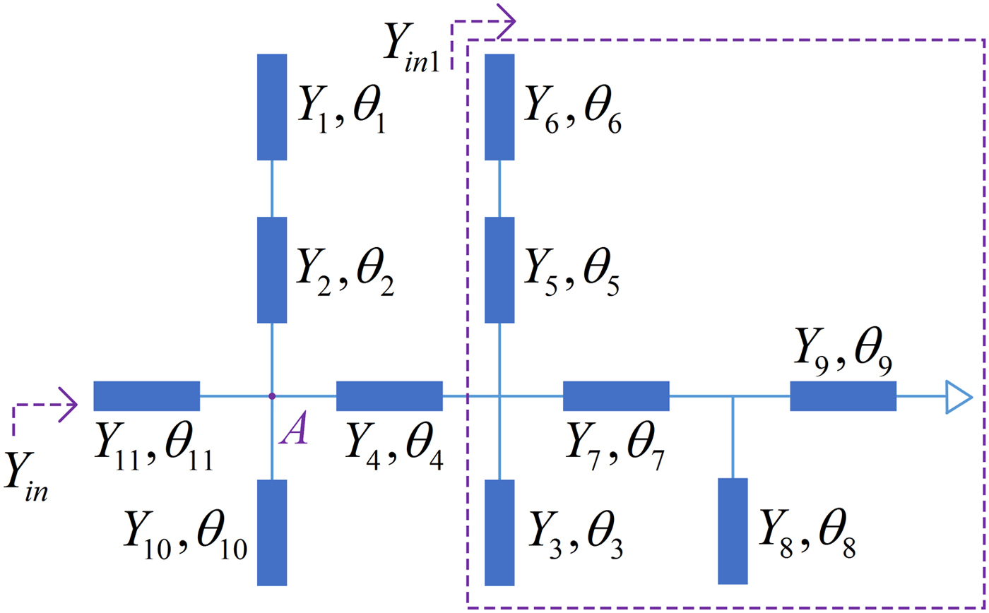
Figure 1 portrays the ideal transmission line model (TML) of the MMSLR. The proposed MMSLR consists of a horizontal short transmission line loaded with five open stubs. θ 1, θ 2……θ 11 denote the electric lengths of the corresponding microstrip lines, and Y 1, Y 2 ……Y 11 indicate the characteristic admittances. For simplicity, Y 1 = Y 6 = Y s; Y 2 = Y 3 = Y 4 = Y 5 = Y 7 = Y 8 = Y 9 = Y 10 = Y 11 = Y t are assumed. Based on the transmission line theory, the resonant condition is that imaginary of the input admittance (Y in) seen from the port is equal to 0, that is,
 $$Im{\rm} (Y_{in}) = 0$$
 $$Y_{in} = Y_t\displaystyle{{Y_{inA} + jY_t\tan \theta _{11}} \over {Y_t + jY_{inA}\tan \theta _{11}}},$$
where Y inA is the input admittance seen from point A.
 $$\eqalign{Y_{inA} = &Y_t\displaystyle{{Y_{in1} + jY_t\tan \theta _4} \over {Y_t + jY_{in1}\tan \theta _4}} \cr & + jY_t\left( {\tan \theta _{10} + \displaystyle{{Y_s\tan \theta _1 + Y_t\tan \theta _2} \over {Y_t-Y_s\tan \theta _1\tan \theta _2}}} \right)} $$
 $$Y_{in1}{\rm}={\rm } jY_t\left( {\displaystyle{{{\rm tan}\theta_8 + \tan \theta_7-{\rm cot}\theta_9} \over {1-({\rm tan}\theta_8-{\rm cot}\theta_9)\tan \theta_7}} + \tan \theta_3 + \displaystyle{{Y_s\tan \theta_6 + Y_t\tan \theta_5} \over {Y_t-Y_s\tan \theta_5\tan \theta_6}}} \right),$$
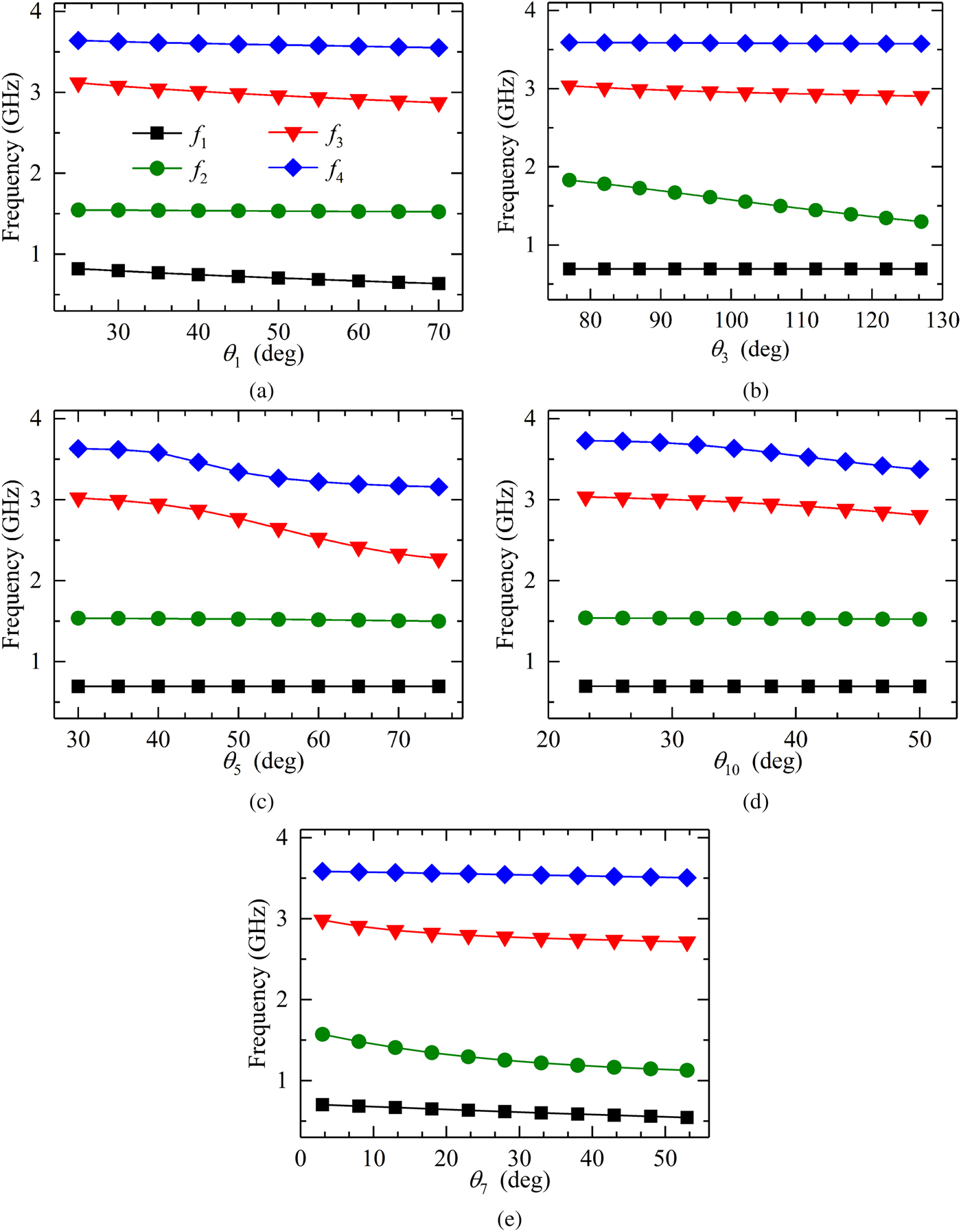
where Y in1 is the admittance in the dashed box seen from left to right. According to the filter design specification, four resonant frequencies can be obtained by calculating from the equations (1)–(4) at the desired passband frequency range. As shown in Fig. 2, four resonant modes are excited, which are denoted by f i (i = 1, 2, 3, 4).

Fig. 1. TML of the proposed MMSLR.

Fig. 2. Resonant frequencies versus varied (a) θ 1, (b) θ 3, (c) θ 5, (d) θ 10, and (e) θ 7.
To explain the influence of the main parameters of the resonator on the resonant frequencies, we investigate the variations of f i versus varied θ 1, θ 3, θ 5, θ 7, and θ 10. It is noted that when one parameter is considered, the others remain unchanged. As illustrated in Fig. 2(a), when θ 1 gets larger, f 1 will decrease and f 3 merely slightly changes, while the others keep constant. As can be seen in Fig. 2(b), the variation of θ 3 just changes f 2 dramatically, whereas it has almost no effect on other fundamental modes. Figure 2(c) demonstrates f 3 and f 4 move toward lower frequency range with the increase of θ 5. In Fig. 2(d), a small variation of θ 10 only impacts on the change of f 4. In Fig. 2(e), it is observed that θ 7 affects the resonant frequency f 1, f 2, f 3 simultaneously, but f 4 remains fixed. Therefore, appropriately choosing different combination of θ 1, θ 3, θ 5, θ 7, and θ 10, f 1, f 2, f 3, and f 4 can be achieved at expected frequency values. According to the aforementioned discussion, the resonant modes of the novel MMSLR can be flexibly controlled.
Quad-band BPF analysis and design
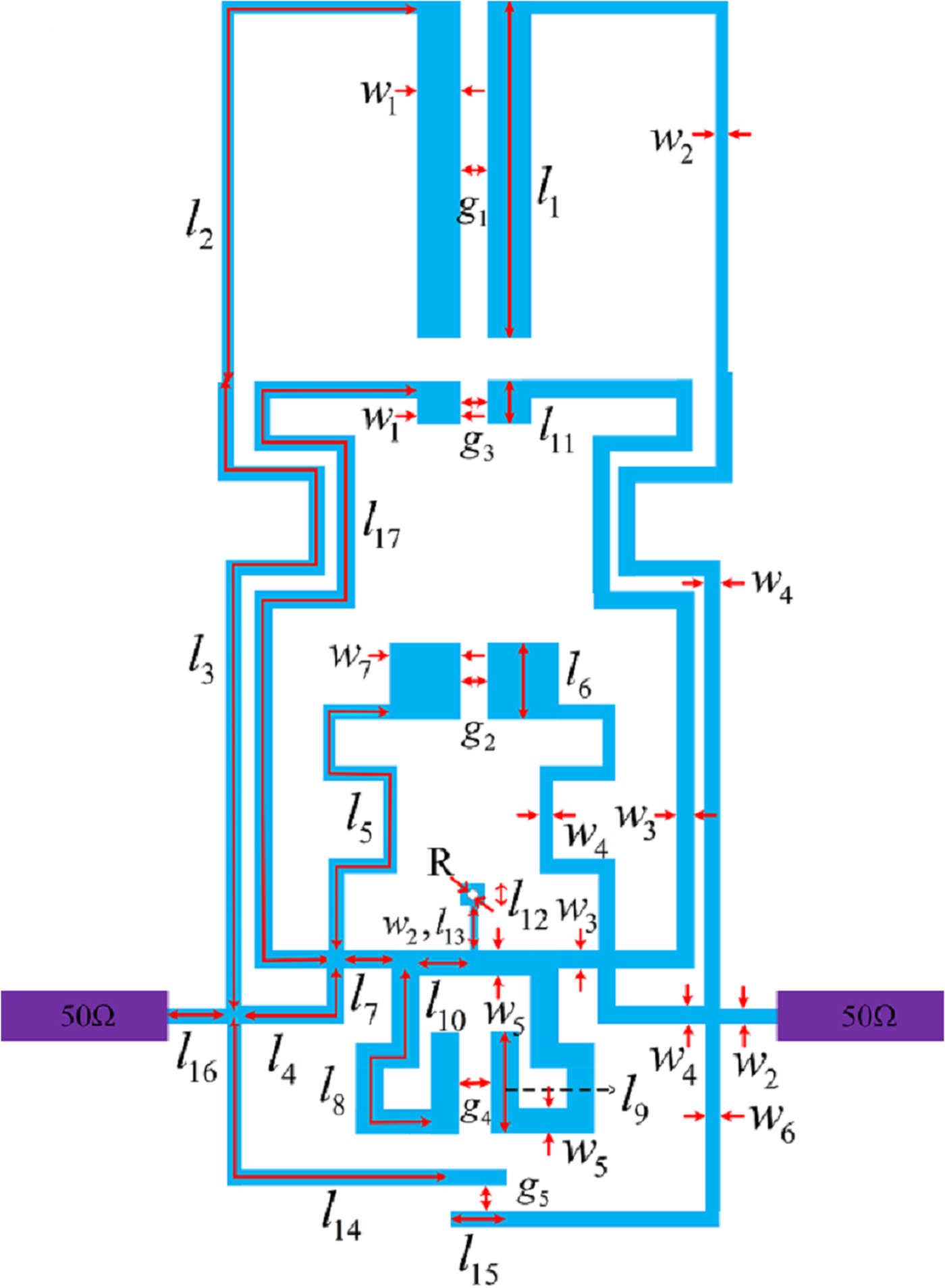
A layout structure of quad-band BPF with multiple coupling structures is sketched in Fig. 3. The designed second-order filter consists of two identical MMSLRs which share a common grounded via-hole. The stubs of the resonator are bent to reduce the overall size of the filter. Two 50 Ω tapped lines are directly connected to short line l 16 segments for serving as I/O ports. Figure 3 depicts configuration that the parallel coupling lines with the lengths l 1, l 6, l 9, l 11 construct electric coupling paths, and a transmission line with length l 10 and width w 5 linked to the ground through a via-hole is a magnetic coupling path. Either electric or magnetic coupling can be dominant by choosing the dimensions of the different coupling parts. The longer the lengths of the coupled sections are and the smaller the gaps are, the stronger the electric coupling strength is. Meanwhile, the longer the lengths of grounded stubs are, the stronger the magnetic coupling strength is. The mixed couplings between two modes have the cancelling effect. When a MEMC is realized in a passband, the stronger coupling method will determine the location of TZ at the stop band [Reference Ma, Ma, Yeo and Do12]. There is an additional TZ generated in the upper stop band as the electric coupling is dominant. To the contrary, an additional TZ generated in the lower stop band as the magnetic coupling is dominant.

Fig. 3. Layout of proposed quad-band BPF.
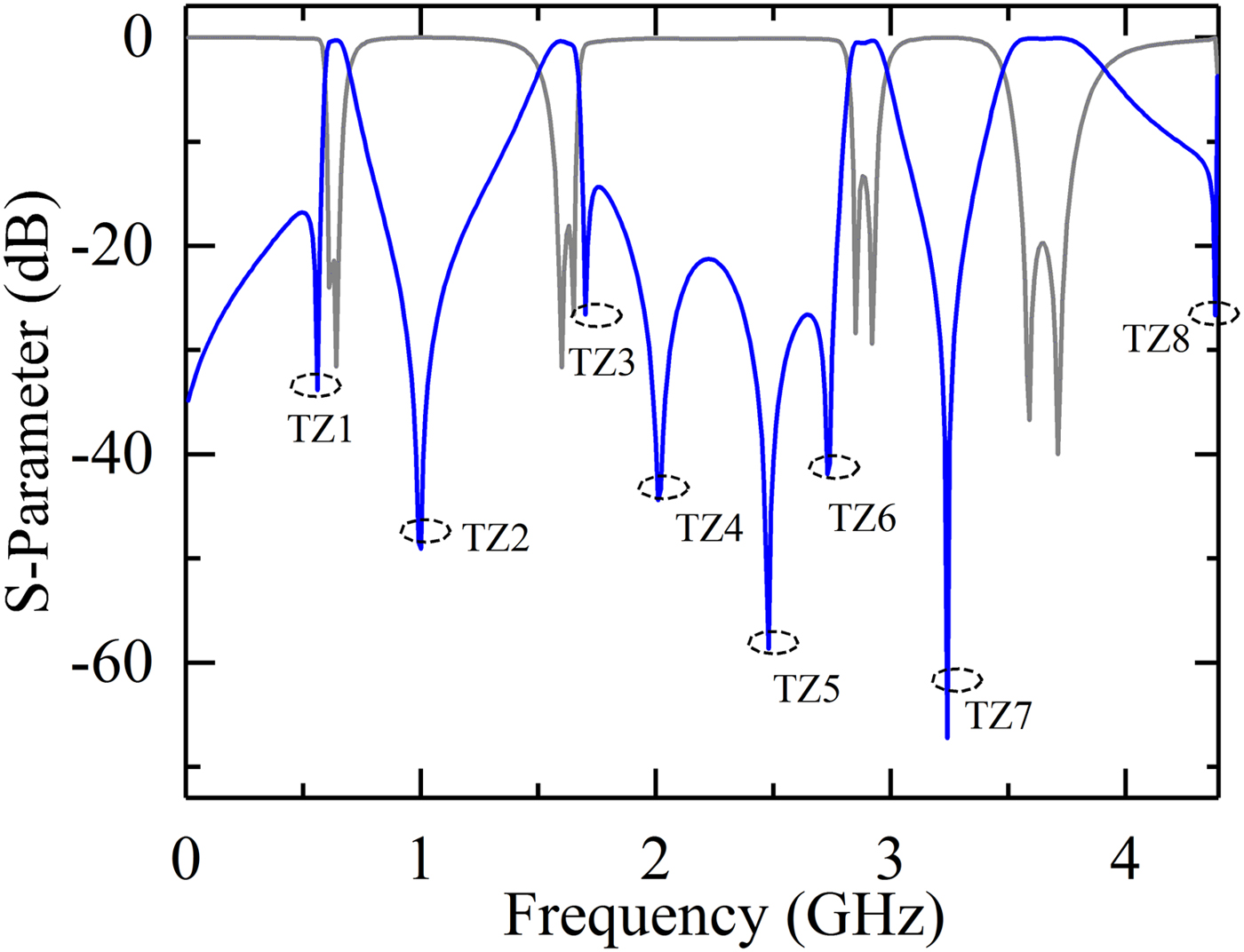
Figure 4 depicts the circuit simulation result of quad-band BPF. The frequency response of |S 11| shows each passband has two transmission poles under the condition of the appropriate coupling. As can be seen, there are eight TZs between the four passbands. The current density distribution diagrams at center frequencies of each passband are illustrated in Fig. 5. The first three diagrams show that the currents concentrate on the transmission lines with lengths l 1, l 11 + l 17, l 5 corresponding to θ 1, θ 3, θ 5 in Fig. 2 at first, second, third passbands, respectively. The last one validates that the fourth passband relates to l 5 + l 6 and l 14 + l 15 and is not associated with l 7, which is consistent with the frequency variation diagrams. Moreover, Fig. 5 indicates that there exists the MEMC in first three passbands. Therefore, three extra TZs are excited because of the cancelling effect of the MEMC. As the electric coupling is dominant in the first and third passbands, the TZ1 and TZ5 locate at the lower stop bands of the first and third passbands, respectively. TZ4 locates at the upper stop band of the second passband since the magnetic coupling is stronger than the electric coupling which is dominant in the second passband. The others are attributed to the virtual ground to short out the transmission signal.

Fig. 4. Frequency responses of |S 21| and |S 11| of proposed quad-band BPF.
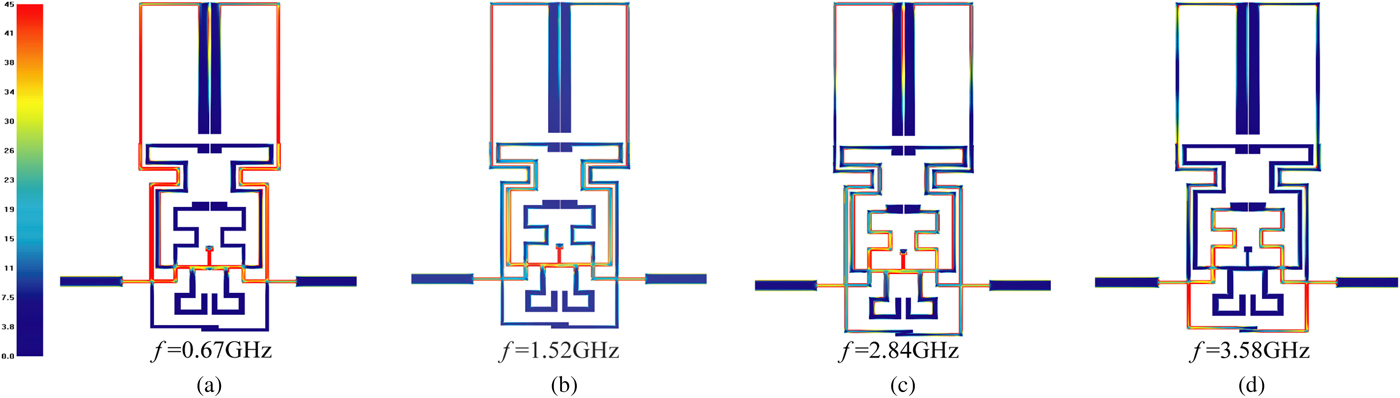
Fig. 5. Current density distribution at (a) f = 0.67 GHz, (b) f = 1.52 GHz, (c) f = 2.84 GHz, and (d) f = 3.58 GHz.
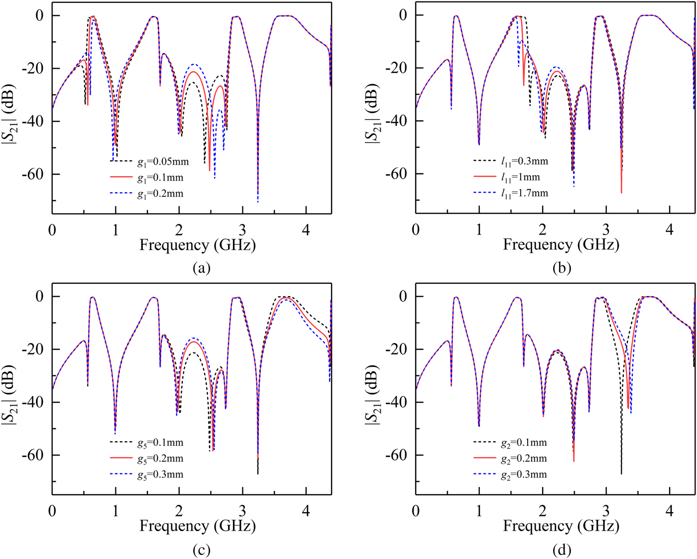
When the external quality factor is fixed, the bandwidths of the filter depend on inter-stage coupling coefficients. It is illustrated that the gap g 1 only affects the bandwidth of the first passband in Fig. 6(a). In Fig. 6(b), when the length l 11 shortens, the bandwidth of the fourth passband will broaden, while the other three passbands are nearly fixed. As is shown in Fig. 6(c), the gap g 5 of the opened coupled line increases, the bandwidth of the last passband will get slightly narrower and the others remain unchanged. In Fig. 6(d), the gap g 2 can tune the position of the seventh TZ, changing the bandwidths of the third and the fourth passbands. Thus, the bandwidths of the four passbands can be independently controlled by tuning corresponding gaps and lengths.

Fig. 6. Simulation |S 21| versus varied (a) g 1, (b) l 11, (c) g 5, and (d) g 2.
Measurement result and discussion
For verification, a quad-band BPF is fabricated and measured. The filter is fabricated on a substrate of Rogers 4003c with parameters: relative dielectric constant of 3.55, thickness of 0.508 mm, and loss tangent of 0.0027. After full-wave EM simulation and optimization, the geometrical dimensions are selected as follows (units: mm): l 1 = 14.1, l 2 = 20.15, l 3 = 20.425, l 4 = 3.3, l 5 = 11.275, l 6 = 0.95, l 7 = l 10 = 1.1, l 8 = 8.55, l 9 = 2.2, l 11 = 1, l 12 = 0.6, l 13 = 1.45, l 14 = 9.125, l 15 = 1.5, l 16 = 2.4, l 17 = 24.775; R = 0.3; g 1 = g 2 = g 3 = g 5 = 0.1, g 4 = 0.35; w 1 = 0.95, w 2 = 0.25, w 3 = 0.4, w 4 = 0.35, w 5 = 0.5, w 6 = 0.3, w 7 = 1.5. The quad-band filter occupies a diminutive circuit area of 15.45 mm × 35.35 mm (excluding the feed lines) which corresponds to 0.058λ g × 0.13λ g, where  $\lambda _g = c/(f_1\cdot \surd \varepsilon _{er})$ is the guided wavelength at the center frequency f 1 of the first passband (εer denotes the effective dielectric constant of the substrate). The photograph of the fabricated quad-band BPF is shown in Fig. 7.
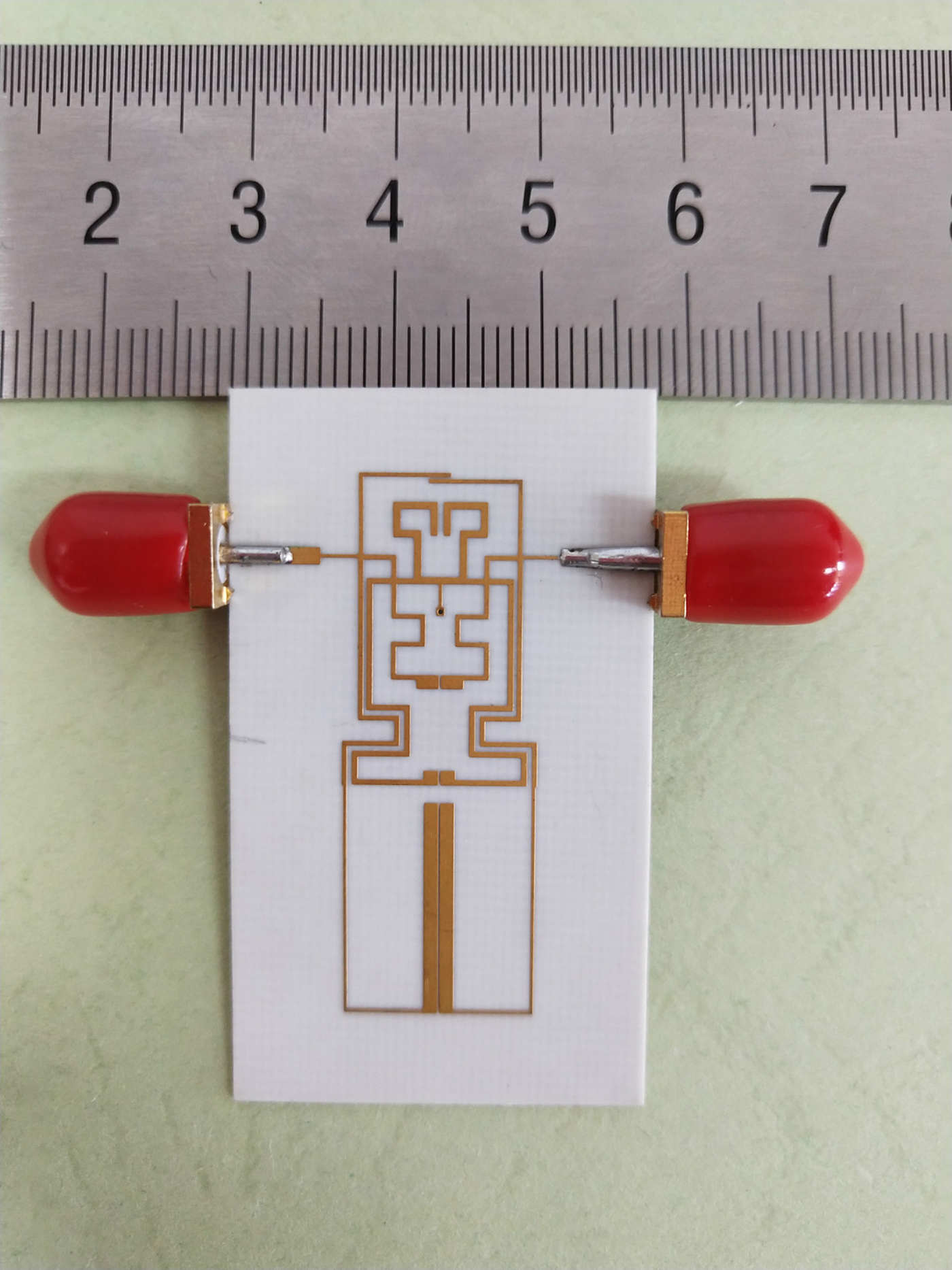
Fig. 7. Photograph of fabricated quad-band BPF.
The designed BPF is measured by an Agilent E5071C vector network analyzer. Figure 8 plots the comparison between the simulated and measured results, which shows great agreement. Fabricated tolerance and SMA connectors contribute to some subtle dissimilarities. The quad-band filter operates at 0.67/1.51/2.84/3.58 GHz with the 3 dB fractional bandwidth (FBW) of 13.4/15.6/9.2/11.5%. The measured minimal insertion losses of four passbands are 1.2/0.91/1.85/2.26 dB, and the return losses are >9.93, >27.2, >17.2, >22.8 dB, respectively. Eight TZs are introduced near the edges of the passbands at 0.6/0.9/1.73/2.05/2.28/2.6/3.2/4.2 GHz with 23.66/43.7/26.5/40.9/34.7/28.9/26.3/14.5 dB rejections, respectively. These TZs greatly improve the passband selectivity and the roll-off skirts. The comparison with other reported quad-band BPFs is summarized in Table 1 which exhibits the excellent superiority: compact size, high passband selectivity, and low insertion.
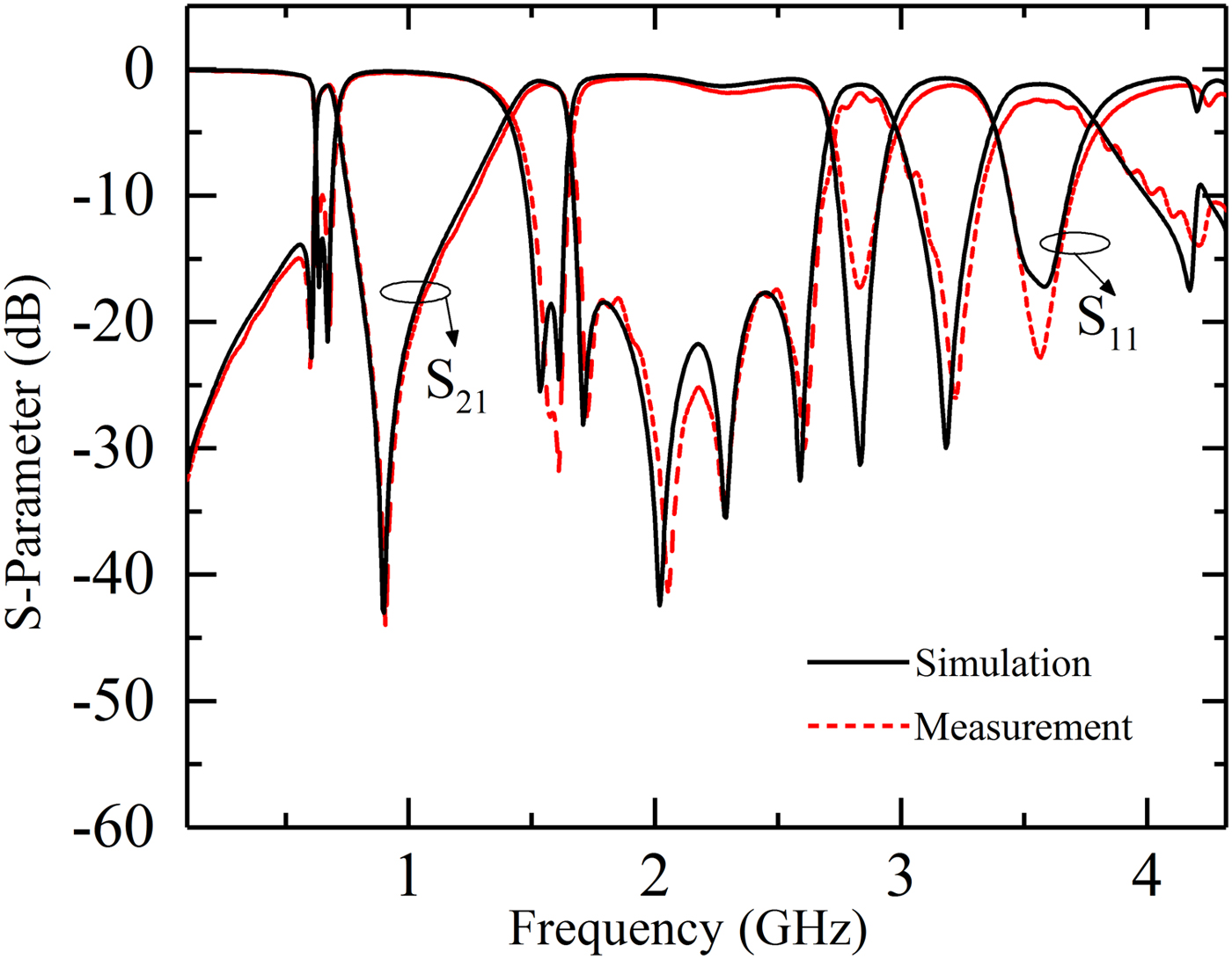
Fig. 8. Simulation and measurement results of fabricated quad-band BPF.
Table 1. Performance comparison with previous quad-band BPFs 159 × 64 mm (600 × 600 DPI)

Conclusion
A quad-band BPF based on proposed novel MMSLR is implemented and fabricated, which confirms the reasonableness of the MMSLR constructing a multi-band filter. The MMSLR can excite four controllable resonant modes and possesses a high freedom degree of frequency design. In addition, the filter has been constructed with multiple electric coupling paths and a magnetic coupling path. The bandwidths can be controlled independently and eight TZs are finally generated so that an excellent attenuation near the passband can be achieved. The designed quad-band BPF with low insertion loss, compact size, and high passband selectivity is very attractive for applications in multiband wireless communication system.
Acknowledgement
This work is supported in part by the National Natural Science Foundation of China under Grants (61471208) and in part by the 111 Project (B16027), the China-Europe Joint Research Center for Solar PV Technology of Tianjin, the International Cooperation Base for New PV Technology, the Key Laboratory of Photoelectronic Thin Film Devices and Technology of Tianjin and the Engineering Research Center of Thin Film Photo-electronics Technology, Ministry of Education.
 Jie Zhou was born in Hejian, Hebei province, China. He received the B.E. degree from Taiyuan University of Technology, Taiyuan, China, in 2017, and is currently working toward the M.E. degree at Nankai University, Tianjin, China. Her main research interests include microwave bandpass filters and multiplexers design.
 LiTian Wang was born in Tianjin, China, in 1991. He is currently working toward the Ph.D. degree at Nankai University, Tianjin, China. His main research interests include microwave passive components and systems, and HTS tunable filter design.
 ZhiPeng Wang was born in Anyang, Henan province, China, in 1996. He is the student member of China Electronics Association now and is currently working toward the M.E. degree at Nankai University, Tianjin, China. His major research interests include the design of microwave tunable filters and high-temperature superconducting tunable filters.
 ShengFang Zhang was born in Liaocheng, Shandong Province, China. She received her B.E. degree in Electronic Information Engineering from Hebei University of Economics and Business in 2017, Shijiazhuang, China. She is currently working toward her M.E. degree in Communication and Information System at Nankai University, Tianjin, China. Her main research interests include microwave bandpass filters and terahertz signal detection.
 Ming He received the M.Eng. and Ph.D. degrees in Electrical Engineering from Nankai University, Tianjin, China, in 2002 and 2008, respectively. Since 1997, he has been with the Department of Electronics, Nankai University, Tianjin, China, where he became a Professor in 2016. From 2004 to 2009, he held several visiting research appointments in Juelich Research Center and Karlsruhe University, Germany. His research interests are in the fields of the applications of high-temperature superconductors, the generation and detection of THz signals, and microwave communications.