1. INTRODUCTION
Global Navigation Satellite Systems (GNSS) and, in particular, the Global Positioning System (GPS), are used widely for positioning to support many applications and services. The multipath effect (resulting from the reception of both direct (Line Of Sight (LOS)) and reflected signals) and Non-Line-Of-Sight (NLOS), or indirect reception of GPS signals results in degraded performance, particularly in built environments such as urban areas. This in turn affects the provision of key services such as those designed to improve transport operations through Intelligent Transport Systems (ITS). A number of ways have already been developed to mitigate the effects of multipath and NLOS, including antenna design, signal processing, observable and measurement-based modelling. Residual multipath effects remain a challenge, however, and, therefore, the detection of such signals would enable appropriate decisions to be made on whether or not to use the measurements for positioning.
Antenna design-based methods include choke-ring antennae, dual-polarisation and antenna arrays. Although effective in mitigating multipath effects from measurements at low elevation angles, such antennae are bulky, heavy and expensive, meaning that they are not appropriate for use in location-based services. They are therefore mostly used in high precision and high accuracy geodetic applications (Tranquilla et al., Reference Tranquilla, Carr and Al-Rizzo1994).
Signal processing-based multipath mitigation was first proposed by Dierendonck et al. (Reference Dierendonck, Fenton and Ford1992) based on narrowing the spacing between early and late receiver code correlators. Subsequently, a popular auto-correlation function based technology, Multipath Estimating Delay Lock Loop (MEDLL), was proposed (Van Nee et al., Reference Van Nee, Siereveld, Fenton and Townsend1994). A review of signal-processing-based multipath mitigation techniques can be found in Braasch (Reference Braasch1996). In addition, numerical optimisations of correlator design, such as the Newton method-based Fast Iterative Maximum-Likelihood Algorithm (FIMLA) (Sahmoudi and Amin, Reference Sahmoudi and Amin2008), and the space-alternating generalised expectation maximisation algorithm (Fessler and Hero, Reference Fessler and Hero1994), have also been developed to further reduce the impact of multipath effects. Advanced receiver-architecture vector tracking is also a promising technique for detecting multipath effects (Bhattacharyya and Gebre-Egziabher, Reference Bhattacharyya and Gebre-Egziabher2014; Hsu et al., Reference Hsu, Jan, Groves and Kubo2015). Ziedan (Reference Ziedan2012) proposed a Principal Components Analysis (PCA) and probabilistic neural network-based method to deal with multipath effects in adaptive tracking. Sokhandan et al. (Reference Sokhandan, Ziedan, Broumandan and Lachapelle2017), meanwhile, proposed a Support Vector Machine (SVM)-based adaptive multipath compensation and tracking strategy to extract context information about the type of multipath environment and the state of motion of a GNSS receiver. Vector tracking, however, requires altering the traditional architecture of the GNSS receiver, which is not currently possible for low-cost GNSS receivers. The signal processing-based methods are therefore designed to mitigate only certain types of multipath effect, and no single method exists that accounts for all these effects.
Observable and measurement-based methods use observables, measurements, satellite and signal information to mitigate multipath effects. Such information can be used to smooth the measurements. Smoothing techniques are based on the fact that carrier phase measurements are less sensitive to multipath signals than code measurements. Furthermore, satellite elevation and signal information (such as the carrier to noise power density ratio) can be used to apply weighting to the measurements in order to contribute to the position solution according to measurement quality in relation to multipath effects (Euler and Goad, Reference Euler and Goad1991; Kuusniemi, Reference Kuusniemi2005). Another way of dealing with multipath effects is to integrate GPS with complementary sensors not affected by such effects. A common approach is to integrate GPS observables or measurements with Inertial Measurement Units (IMU) (Cox, Reference Cox1978; Yang et al., Reference Yang, Shi and Chen2018). The coupling, or integration, could be in the position domain (that is, using positioning outputs of GPS), measurement domains (that is, using carrier phase or code observables from GPS) or tracking loop domain (that is, using the code/carrier discriminator output of GPS). Although GNSS/IMU integration is effective if high grade IMU sensors are used, the expense associated with such sensors precludes their use in location-based services.
In the case of NLOS reception, the ranging measurement errors that result from NLOS reception are different from those produced by multipath interference, and therefore cannot be corrected by most multipath mitigation techniques (Groves et al., Reference Groves, Jiang, Rudi and Strode2013). Although it has been shown that a dual-polarisation antenna is able to detect NLOS reception, such an antenna is expensive and bulky compared with patch antennae, again preventing their use for location-based services (Izadpanah et al., Reference Izadpanah, O'Driscoll and Lachapelle2008; Jiang and Groves, Reference Jiang and Groves2014; Palamartchouk et al., Reference Palamartchouk, Clarke, Edwards and Tiwari2015). Another potential solution is to apply a consistency check, which is based on multipath/NLOS contaminated measurements that are not consistent with other clean measurements (Groves and Jiang, Reference Groves and Jiang2013). Consistency checks between pseudorange measurements can detect and exclude multipath and NLOS effects when the number of clean measurements is sufficient (Hsu et al., Reference Hsu, Tokura H and Gu Y2017).
More recently, research has focused on the use of spatial data (for example, Three-Dimensional (3D) city models) to assist in the detection of NLOS reception and to improve positioning, such as GNSS shadow matching in built environments (Groves, Reference Groves2011). In these approaches, 3D building models are used to detect satellite visibility, enabling NLOS signals to be used to actually improve positioning accuracy, in contrast to the methods that detect and exclude NLOS that have the effect of significantly lowering satellite availability for positioning (Betaille et al., Reference Betaille, Peyret, Ortiz, Miquel and Fontenay2013; Peyraud et al., Reference Peyraud, Bétaille, Renault, Ortiz, Mougel, Meizel and Peyret2013). By including NLOS by the prediction of satellites’ azimuth and elevation angles, a cross-street accuracy of 5 m (54.3%) can be achieved by shadow matching (Wang et al., Reference Wang, Groves and Ziebart2015). Subsequently, the NLOS measurement is further corrected using the method called ray-tracing simulation. It has been claimed that a positioning accuracy of 4.4 m (1σ) is achievable for pedestrian applications (Hsu et al., Reference Hsu, Gu and Kamijo2016). Research has been released illustrating the acceleration of ray tracing simulation with an associated enhancement of the 3D building model GNSS positioning method (Ziedan, Reference Ziedan2017). Recently, shadow matching has been integrated with range-based 3D mapping aided algorithms (Adjrad and Groves, Reference Adjrad and Groves2016; Suzuki, Reference Suzuki2016).
To use the NLOS information, it must be detected correctly. Positioning accuracy is therefore highly dependent on the ability to classify the signals correctly. The satellite reception classification method is not robust enough, however, to achieve this when using the traditional single variable-based method (usually signal to noise ratio (C/N0)-based), which will always be suboptimal, since the status cannot be exactly known when it is determined by only one variable, especially in complex city environments. The concept of applying machine learning to improve GNSS positioning accuracy and classify measurement types has emerged in recent years and has exhibited superior ability by considering various sources of information from the GNSS measurement to improve the successful rate of signal reception classification. The general idea is demonstrated in Figure 1.

Figure 1. Demonstration of the idea for training using a machine learning approach.
The related research can be illustrated as follows. Wang et al. (Reference Wang, Kao and Chen2013a) proposed the Wilcoxon-norm-regressor based on pseudorange residuals to detect biased pseudorange measurements. Phan et al. (Reference Phan, Tan, McLoughlin and Vu2013) used elevation and azimuth angles as the key features for SVM to mitigate the multipath effect for static applications. Sokhandan et al. (Reference Sokhandan, Ziedan, Broumandan and Lachapelle2017) extracted variables from the correlators in the receiver signal processing stages to classify the different types of scenarios for GNSS receivers. A decision tree-based approach has also been used to classify LOS and NLOS based on received signal strength and elevation angle (Yozevitch et al., Reference Yozevitch, Moshe and Weissman2016). In this paper, it was indicated that the accuracy of the classification prediction would be highly dependent on how the tree is designed according to the selection of features. It is difficult to obtain a trade-off balancing sufficiently high accuracy with sufficiently low computation load with this decision tree algorithm, since the features have to be selected manually. If we could design an algorithm which is able to choose the related features automatically, however, based on all the known representative variables and then use these related features for the classification algorithm that would improve the LOS/NLOS classification performance.
This paper develops a novel Adaptive Neuro Fuzzy Inference System (ANFIS)-based algorithm to classify the received signals using the known representative variables from GPS raw measurements: that is, the Received Signal Strength (RSS), temporal Difference of Received Signal Strength (Δ RSS), Horizontal Dilution Of Precision (HDOP), Vertical Dilution Of Precision (VDOP), satellite Elevation Angle (EA) and Azimuth Angle (AA), pseudorange residual (η), consistency between delta pseudorange and pseudorange rate (ζ) and Number of visible Satellites (NS). ANFIS is a machine learning method that uses a combination of neural network and fuzzy logic to produce a more reliable output by considering various input sources. The application of ANFIS varies, covering different disciplines such as disease diagnosis, control engineering and share price forecasting, etc. (Ubeyli, Reference Ubeyli2009; Jilani et al., Reference Jilani, Murawwat and Jilani2015; Wei, Reference Wei2016). It potentially has great advantages over other machine learning methods for GPS signal reception classification application. For example, as mentioned in Pradhan (Reference Pradhan2013), the ANFIS-based models have exhibited superior predictive ability than some other machine learning methods (such as decision tree and SVM) in landslide susceptibility mapping. In the training phase, the algorithm is aided by ray-tracing simulation and a 3D city model for offline data labelling. PCA is then used to extract the principal components, which are fed into the ANFIS-based training algorithm to output the Fuzzy Inference System (FIS) rules. The variables captured in real-time are processed based on the extraction of PCA features and are then fed into the FIS rules in order to output the classification results. The designed ANFIS-based algorithm requires no additional hardware costs and is therefore suitable for city-based applications with low-cost GNSS receivers. The method is also easily extendable to multi-constellation GNSS for practical implementation. The multi-variable-based classification, considering various sources of information from GPS measurements, has the potential to provide a robust signal reception classification, and therefore address the limitations of the current single variable-based classification approach.
2. ALGORITHM DESIGN
2.1. Process overview
A flowchart of the ANFIS based LOS/Multipath/NLOS classification is presented in Figure 2.

Figure 2. The algorithm flow diagram.
First, an offline dataset is created, including a large amount of LOS, multipath and NLOS data. The LOS data is collected and labelled as the GPS measurements from a GPS reference station, which is in an open area, therefore offering clean data. The multipath and NLOS data are collected in a densely built-up area in static mode and labelled based on ray-tracing and 3D building models (Section 3.1). PCA is then applied to extract the relevant combination of variables for dimension reduction (Section 2.2). Based on the dataset, ANFIS-based training is carried out to output the trained FIS rules (Section 2.3). These rules are then used together with the principal components extracted from the actual real-time measurements by FIS for classification of the signals in terms of LOS, multipath and NLOS.
2.2. Determination of variables for GPS LOS, multipath and NLOS signal classification
2.2.1. Derivation of GPS variables from raw data
The raw data consists of pseudorange and carrier phase measurements, the carrier to noise ratio, and the Doppler shift frequency in the Receiver Independent Exchange (RINEX) format (Gurtner, Reference Gurtner1994). It is therefore assumed in this paper that the potential features extracted from the GPS raw data can be obtained from most new GNSS devices. The received GPS signal contains a variety of information that can be used to determine signal reception. These differences can be distinguished by the careful application of a number of variables as follows.
RSS: This is usually represented by C/N0. The effect of signal reflection and additional travel time is to increase the signal propagation loss. C/N0 is, therefore, commonly used in the mitigation of multipath effects (Hartinger and Brunner, Reference Hartinger and Brunner1999).
Δ RSS: Due to the estimation of both received signal strength in the
receiver tracking loop, the received signal strength of multipath and NLOS could increase if the antenna remains static. The temporal difference in the received signal strength is calculated as:
 $$\Delta {RSS}_{k}^{\lpar i\rpar }={RSS}_{k}^{\lpar i\rpar }-{RSS}_{k-1}^{\lpar i\rpar } $$
where i is the satellite and k the epoch. As shown in previous research, the speed of the antenna is strongly related to the change rate of the multipath effect (Kubo et al., Reference Kubo, Kobayashi, Hsu and Amai2017).
HDOP and VDOP: HDOP and VDOP indicate the strength of the geometric distribution of satellites in relation to the user's horizontal and vertical positioning dimensions, respectively. Conventionally, positioning error is closely related to the product of the strength of the geometric distribution (that is, Dilution Of Precision (DOP)) and the measurement error. In addition, areas with strong multipath and NLOS effects tend to have larger DOP values, mainly because of the surrounding physical features.
EA and AA: Measurements transmitted from higher elevation angles experience fewer multipath effects. It is therefore common to use the elevation angle as a weighting metric to reduce the multipath effect on the positioning accuracy (Euler and Goad, Reference Euler and Goad1991).
In addition to the variables above, the consistency of the measurements should be considered, including pseudorange residuals and between delta pseudorange and pseudorange rate.
η: Least squares estimation is a basic optimisation method used for
state estimation. The receiver state is estimated as:
 $$r=\lpar G^{T}G\rpar ^{-1}G^{T}\rho $$
where r is the receiver state, including 3D position and the clock offset between the receiver and GPS system time. ρ denotes the pseudorange measurements and G denotes the design matrix consisting of the unit LOS vector between the satellite and receiver. The inconsistency between the pseudorange measurements represented by η is calculated as:
 $$\eta =\rho -G {\bf \cdot} r $$
Hsu et al. (Reference Hsu, Tokura H and Gu Y2017) showed that the pseudorange residual could potentially be used as an indicator to exclude the multipath and NLOS signals if the number of measurements is sufficient.
ζ: The pseudorange and Doppler shift are estimated by the delay and frequency lock loops, respectively. They are independent if their minor cross-correlation is neglected. Delta pseudorange indicates the change of pseudorange between two epochs. It is calculated by:
 $$\Delta \rho_{k}^{\lpar i\rpar }=\rho_{k}^{\lpar i\rpar }-\rho_{k-1}^{\lpar i\rpar } $$
where ρ is the pseudorange measurement and k the time in seconds. The pseudorange rate  $\dot{\rho }$ is the change of pseudorange between two epochs. It is calculated from the Doppler shift as:
 $$\dot{\rho }^{\lpar i\rpar }=-\displaystyle{{c\lpar f_{Doppler}^{\lpar i\rpar }\rpar }\over{f_{L1}}} $$
where  $f_{Doppler}^{\lpar i\rpar }$ is the Doppler shift in Hz, c is the speed of light and f L1 is the GPS L1 band carrier frequency of 1,575.42 MHz. Thus, their difference can be calculated as:
 $$\zeta =\vert \Delta \rho -\dot{\rho}\Delta t\vert $$
where Δ t is the time difference between two epochs.
NS: The number of the satellites tracked by the GPS receiver can be easily obtained from the National Marine Electronics Association (NMEA) GPGGA message.
The nine variables are the inputs to the feature extraction algorithm.
2.2.2. Feature extraction using Principal Components Analysis (PCA)
PCA is applied to the GPS variables for pre-processing to extract the key features, reduce the dimensions and, therefore, simplify the rules for the ANFIS in the next step. The details of PCA are in Smith (Reference Smith2002). The first four Principal Components (PCs) extracted, which are linear combinations of the input GPS variables, represent 96.82% of the whole measurement information as shown in Figure 3. The blue line indicates the value of the accumulated percentage of the first m PCs. In this figure, we have obtained the first four PCs, which contribute to 96.82% of the total features. Table 1 shows the links between the GPS variables and the extracted PCs. The nine derived GPS variables mentioned in Section 2.2.1 are denoted as x 1…x 9 respectively. The values within Table 1 show the weights of the defined variable for the corresponding PC. Positive values indicate a positive correlation of the variables to the corresponding PC, while negative values indicate a negative correlation. The larger the value of the corresponding variable, the higher the importance of the variable for the PC. Therefore, the linear combination equations can be derived for the first four PCs based on Table 1. It is indicated that PC1 is mainly the linear combination of the number of satellites and C/N0. PC2 is mainly formed by the linear combination of the azimuth angles. PC3 is mainly formed by the linear combination of the elevations. PC4 is mainly formed by the C/N0 and the number of satellites.

Figure 3. The first four PCs extracted and the accumulated variation represented by each PC.
Table 1. The relationship between the GPS variables and the extracted PCs

2.3. ANFIS-based classification model
Generally, ANFIS is the integration of Neural Network (NN) architectures with FIS. It is able not only to take linguistic rules from human experts, but also to adapt itself using input-output data to achieve better performance. Mamdani and Sugeno are two types of basic fuzzy systems. In these systems, the first two parts of the fuzzy inference process, fuzzifying the inputs and applying the fuzzy operator, are the same. The main difference between Mamdani and Sugeno is that the Sugeno output membership functions are either linear or constant. In ANFIS, therefore, the Sugeno type is used since it can output linear or constant membership functions (Jang, Reference Jang1993).
From our initial analysis, although the classification accuracy could be improved if we increase the use of PCs, similar accuracy results are obtained by using four PCs and five PCs. However, the computation load of five PCs is much higher than that of four PCs. Therefore, four PCs are adopted for our ANFIS algorithm. The five layers for the generated structure of the ANFIS-based classification are presented in Figure 4.

Figure 4. Structure of the ANFIS based GPS LOS, multipath and NLOS signal classification.
Layer 1 assumes that every node i in this layer is shown as a square with a node function:
 $$O_{i}^{1}=\mu_{A_{i}}\lpar {\rm PC1}\rpar $$
where PC1 is the input of node i and A i is the linguistic label (for example, small, medium, large, very large). Node  $i O_{i}^{1}$ is the membership function of A i and it specifies the degree to which the given PC1 satisfies the quantifier A i. In our case, the initial membership functions
  $\mu_{A_{i}}\lpar {\rm PC1}\rpar $ are set as a Gaussian function with maximum value equal to 1 and minimum value equal to 0 based on the characteristics of the input information:
 $$\mu_{A_{i}}\lpar {\rm PC1}=Gaussian\ \lpar {\rm PC1}\semicolon \; \sigma c\rpar =\hbox{e}^{e^{-\displaystyle{{\lpar {\rm PC1}-c\rpar ^{2}}\over{2\sigma^{2}}}}} $$
where c is the parameter to determine the centre of the membership function and σ determines the width of the curve. As the values of these parameters change, the Gaussian membership functions vary accordingly, thus exhibiting various forms of membership function on linguistic label A i.
PC2, PC3, PC4 and their corresponding initial membership functions  $\mu_{B_{i}}\lpar {\rm PC2}\rpar $,
  $\mu_{C_{i}}\lpar {\rm PC3}\rpar $ and
  $\mu_{D_{i}}\lpar {\rm PC4}\rpar $ are defined based on the same method. The initial rule can then be extracted based on the first-order Sugeno fuzzy model (Takagi and Sugeno, Reference Takagi and Sugeno1983):
 $$f_{i}=p_{i}\ast {\rm PC}1+q_{i}\ast {\rm PC}2+r_{i}\ast {\rm PC}3+s_{i}\ast {\rm PC}4+t_{i} $$
where the membership functions will be modified along with the parameters p 1, q 1, r 1, s 1 and t 1 during the following NN training. f i is the initial i-th rule. The parameters in this layer are considered as the premise parameters.
In Layer 2, every node is a circle node labelled ∏![]() , which multiplies the incoming signals and sends the product out. Each node in this layer calculates the firing strength of each rule via multiplication, noted as w i. In our case, we use the AND T-norm operator here, given by:
, which multiplies the incoming signals and sends the product out. Each node in this layer calculates the firing strength of each rule via multiplication, noted as w i. In our case, we use the AND T-norm operator here, given by:
 $${O_{i}^{2}=w}_{i}=\mu_{A_{i}}\lpar {\rm PC1} \rpar \ast \mu_{B_{i}}\lpar {\rm PC2} \rpar \ast \mu_{C_{i}}\lpar {\rm PC3}\rpar \ast \mu_{D_{i}}\lpar {\rm PC4} \rpar \comma \; i=1\comma \; 2\comma \; 3\comma \; 4 $$
 In Layer 3, every node is a circle node labelled N. The i-th node of this layer calculates the ratio of the i-th rule's firing strength to the sum of all the rules’ firing strengths, which is represented by  $\bar{w}_{i}$.
 $$O_{i}^{3}=\bar{w}_{i}=\displaystyle{{w_{i}}\over{w_{1}+w_{2}{+w}_{3}+w_{4}}}\comma \; i=1\comma \; 2\comma \; 3\comma \; 4 $$
In Layer 4, the multiplication of the input from Layers 3 and 1 is implemented, given by:
 $$O_{i}^{4}=\bar{w}_{i}f^{\prime}_{i}=\bar{w}_{i}\lpar p^{\prime}_{i}\ast {\rm PC1}+q^{\prime}_{i}\ast {\rm PC2}+r^{\prime}_{i}\ast {\rm PC3}+s^{\prime}_{i}\ast {\rm PC4}+t^{\prime}_{i}\rpar $$
where  $\bar{w}_{i}$ is the output of Layer 3 and
  $p^{\prime}_{i} q^{\prime}_{i} r^{\prime}_{i} s^{\prime}_{i} t^{\prime}_{i}$ is the parameter set. Parameters in this layer are called consequent parameters, which have been modified after NN training. f′i here is the output of the i-th rule.
Layer 5 computes the overall outputs as the summation of all incoming signals:
 $$\sum_i {\bar{w}_{i}f_{i}} =\displaystyle{{\sum\nolimits_i {w_{i}\ast f_{i}} }\over{\sum\nolimits_i w_{i}}} $$
Subtractive clustering is applied for the initial FIS design in order to reduce the computation complexity (Chiu, Reference Chiu1994). In addition, during the learning process, the premise parameters in Layer 1, and the consequent parameters in Layer 4, are tuned until the desired response of the FIS is achieved.
3. FIELD TEST AND RESULTS ANALYSIS
3.1. Experiment setup – data collection, labelling and processing
We created five datasets collected from four different locations. The relationships between these datasets are depicted in Figure 5.

Figure 5. The relationship of the datasets in the field test.
To create the combined dataset D0, two types of data were collected. One was collected in location A from an urban canyon (NLOS and multipath) and the other was collected from location R at the SatRef HKSC station (LOS). To record a large amount of multipath and NLOS data, a static experiment was carried out in location A, a densely built-up area in Hung Hom, Hong Kong (HK). The left and middle panels of Figure 6 show the environment in which the data for location A were collected. The antenna was attached to a pole stuck out of a window. A commercial GPS receiver, a u-blox NEO-M8T, was deployed to collect multipath and NLOS data. 24 hours of raw GPS measurements were collected. In this dataset, and because of the environment, most of the measurements were affected by the buildings in the vicinity. In other words, the urban dataset should consist predominantly of multipath and NLOS measurements.

Figure 6. The left panel indicates the installation of the patch antenna, the middle panel illustrates the data collection environment and the right panel indicates the skyplot with building sites used to label NLOS and multipath measurements.
A ray-tracing method to identify the signal reception types was applied for labelling the multipath and NLOS signals in the urban canyons. The principle of ray-tracing in GPS is to use known satellites, reflector and receiver geometry to trace the direct and reflecting paths (Lau and Cross, Reference Lau and Cross2007). Satellite positions can be estimated from the broadcast ephemeris. A 3D building model was used to search for reflectors. The ground truth was provided by a topographic map from the Land Department of the HK government with a 2D accuracy of 20 cm. The height was determined from Google maps plus the height of the equipment.
Once the positions of the satellite, reflector and receiver were known, ray-tracing was performed. The right panel of Figure 6 shows the skyplot with building sites. This skyplot was generated using ray-tracing simulation and a 3D building model. The grey area indicates where the direct transmission was blocked according to the building models. If the elevation and azimuth angles of a satellite were blocked according the tailored skyplot, its measurements were labelled as NLOS. Otherwise, they were labelled as multipath, that is, we assume that all non-NLOS measurements are multipath. Regarding LOS (clean) GPS data, the HK Land Department has established a GPS network called SatRef to provide differential corrections for HK users. The archived RINEX data of the location R, which is the SatRef HKSC station, were used as the LOS data because it is located in a clear environment. 24 hours of clean data were collected with a measurement update interval of 30 seconds.
The training dataset D1 was randomly selected from the dataset D0 and the testing dataset D2 was randomly selected from the rest of the dataset D0 (excluding D1). Although some of the variables will be correlated over time, the time dependency of the data does not affect the ANFIS performance, since the algorithm treats each epoch as an independent event. The training dataset, D1, contained 24,000 measurement samples, with nine variables for each sample, of which a third were labelled as LOS/multipath/NLOS data (labelled by the 3D map and ray tracing) and were processed with PCA to extract the four principal components to feed the ANFIS for offline training. The ANFIS rules were extracted from this training.
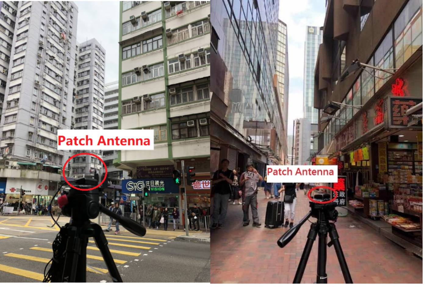
The testing dataset, D2, contained 24,000 measurement samples, with nine variables for each sample, of which a third each were LOS, multipath and NLOS (reference label - labelled by the 3D map and ray tracing). To determine the performance of the input testing dataset, we first created a reference label called ‘unknown’, manually deleting the labelled signal reception in advance. We then marked the signal reception as ‘unknown’ for the test set and processed this with PCA, and then fed the extracted features into the ANFIS rules trained from the dataset D0. We then compared the results from the ANFIS predicted signal reception with the reference label to compute the accuracy. In order to further verify the validity of the extracted rules, two more testing datasets collected from other locations were also used to feed the rules. One testing dataset, D3, was collected from location B, which is close to location A in the urban canyon, while the other testing dataset, D4, was collected from location C, which is about three blocks away from location A in the urban canyon, see Figure 7. A summary of the datasets is shown in Table 2.

Figure 7. GPS data collection environment for location B (left) and location C (right).
Table 2. Summary of the datasets

3.2. Results comparison and analysis
Figure 8 compares the results from the ANFIS prediction with the reference label (signal reception labelled by the 3D map and ray-tracing) based on dataset D2. It is clear that the LOS signals can be identified with a high accuracy of 100%, while the errors of classification are entirely distributed in the multipath and NLOS areas. The predicted values are further rounded to the closest value of 1, 0 or −1. For example, if the ANFIS predicted value is within the interval of [−0.5, 0.5], it will be rounded to the value 0 (multipath). Some NLOS measurements were misclassified as multipath in the experimental results. The reason for the errors distributed in the multipath and NLOS areas are attributable to 3D map border errors and scattered reflection in the labelling stage. In this paper, the shapes of the buildings are considered to be cuboid, whereas in reality the roofs of some buildings are likely to have different shapes; errors may be induced during the labelling stage when we are using the ray-tracing method. In addition, we did not consider scattered reflection when using ray-tracing, which means we assume the signal could only be reflected once during propagation.

Figure 8. Comparison of the ANFIS predicted results for testing dataset D2 and the labelled reference. 1, 0 and − 1 of y-axis denote LOS, multipath and NLOS for the output variable, respectively.
The following paragraphs compare the proposed ANFIS based algorithm with other state-of-the-art algorithms for signal reception identification based on different testing datasets. Specifically, Decision Tree and SVM, two typical machine learning methods that could be used for the identification of satellite visibility (Yozevitch et al., Reference Yozevitch, Moshe and Weissman2016; Hsu, Reference Hsu2017). Both can be used for multi-variable based classification and traditional single C/N0-based classification, and are compared with the ANFIS-based algorithm designed here.
The confusion matrix of the LOS, multipath and NLOS (1, 0 and −1) classification results for different algorithms based on the testing datasets D2 are listed and compared in Table 3. The rows labelled Accuracy are calculated as the ratio (as a percentage) of the number of correctly detected activities to the total number of known activities (Blasch et al., Reference Blasch, Salerno and Tadda2011). It is obvious that the proposed ANFIS algorithm outperforms Decision Tree, SVM and traditional C/N0-based classification, with a total classification accuracy of 91.8%. NLOS detection accuracy is calculated as the ratio (as a percentage) of the number of instances correctly classified as NLOS to the total number of known NLOS instances, which is labelled NLOS. In particular, the ANFIS-based algorithm significantly improves the accuracy of the NLOS detection with an accuracy of 91.1%, while it is 49.5%, 65.1% and 64.9% for the Decision Tree, SVM and single C/N0-based algorithms.
Table 3. Confusion matrix of LOS (noted as 1), multipath (noted as 0) and NLOS (noted as −1) classification results for testing dataset D 2

The multipath detection accuracy is calculated as the ratio (as a percentage) of the number of instances correctly classified as multipath to the number of total known instances of multipath, which is labelled multipath. For multipath detection accuracy, the ANFIS also has a high detection accuracy of 84.1%. Although the decision tree-based method performs slightly better with a detection accuracy of 89.5%, it also has a higher number of misdetections, where NLOS signals are incorrectly identified as multipath. It is also noted that the overall performance of the classification accuracy for the multi-variable-based algorithms (Proposed ANFIS, Decision Tree and SVM) is superior to the single C/N0-based algorithms.
Although the proposed ANFIS-based algorithm has superior performance based on the testing dataset D2, more testing databases from other locations were used to verify the validity of the proposed algorithm. As mentioned in Section 3.1, dataset D3 and dataset D4 were collected to feed the extracted rules from training dataset D1 to identify the GPS signal reception classification. Since locations B and C are both in the urban canyon, we can only obtain NLOS and multipath signals. The labelling of NLOS and multipath is also based on the 3D city model and ray-tracing introduced in Section 3.1. It should be noted that it is difficult for us to get NLOS, LOS and multipath data in one environment. Even if this kind of environment exists, it would still not be possible to label the data based on the current 3D city model and ray-tracing-based method as one cannot determine the ‘true’ LOS existing in the area where multipath and NLOS exist.
The classification accuracy based on different algorithms for the testing datasets D3 and D4 are listed and compared in Table 4. The ANFIS has a similar performance to SVM but with a faster calculation speed. ANFIS will therefore be more suitable than SVM for real-time applications. The classification accuracy of the ANFIS-based results for datasets D3 and D4 is much worse than it is in the case of dataset D2, which indicates the data sensitivity of the proposed algorithm. In addition, we have found that when conducting a PCA process on datasets D3 and D4, although the main components in the PCs were the same as they were in D0, D1 and D2, the percentages for the main PCs vary across the different collecting locations. Furthermore, we have also found that if we use parts of the data from D3 or D4 for training and the rest for testing, respectively, the proposed ANFIS could still perform with very high accuracy. This means that for the proposed ANFIS algorithm, if the training and testing data are from the same dataset, highly accurate classification results can be obtained. That brings us to the idea that the rules extracted from the ANFIS might not be suitable for different environments due to changing the built environment factors, such as the materials of the building surface. This suggests that real-time on-line training algorithms may be a logical next step in this line of research.
Table 4. The Multipath (noted as 0) and NLOS (noted as −1) classification results for testing dataset D 3 and D 4

4. CONCLUSION AND FUTURE WORK
This paper has presented an ANFIS-based multi-variable-based GPS measurement classification algorithm for the identification of LOS, multipath and NLOS measurements by considering the known representative variables from GPS raw measurements. The experimental results show that the proposed algorithm delivers an overall detection accuracy of 91.76% using a static test based on the testing datasets from the same locations as the training datasets, with 91.1% and 84.1% for the NLOS and multipath classification accuracy, respectively. This is significantly higher than the other three approaches (that is, Decision Tree, SVM and C/N0-based classification), whose overall performances range from 67.1% to 80.1%. For the testing results from datasets D3 and D4 however, which are not collected from the same location as the training data D1, the changing of the environment degraded the algorithm performance, pointing to the sensitivity of the algorithm to such issues.
In the future, an online data training mechanism will be combined with the ANFIS-based decision system to build a real-time applicable system to achieve high classification accuracy. In addition, the ANFIS classifier will be integrated with a consistency-check system to exclude the multipath/NLOS measurements from the GPS single point positioning.
ACKNOWLEDGEMENTS
The authors are grateful for the sponsorship of the National Natural Science Foundation of China (Grant No.41704022), National Natural Science Foundation of Jiangsu Province (Grant No. BK20170780), China Postdoctoral Science Foundation funded Project (Grant No. 2017M623360), Shenzhen Municipal Science and Technology Innovation Committee (Grant No. JCYJ20170818103653507).