


Introduction
Radiotherapy should not only be aimed to cure cancer but also should be intended to minimise the chances of complications, which may develop in critical organs. Recently with the advancement in computer-controlled linear accelerators (LINACs) and treatment planning systems (TPSs), conformal dose distributions sparing normal tissues are achievable while planning breast radiotherapy. New treatment techniques are now employed for this. Several authors have examined the efficacy of advanced techniques such as field in field (FiF), irregular surface compensator (ISC), intensity-modulated radiotherapy (IMRT) and rapid arc (RA) over the three-dimensional conventional radiotherapy (3DCRT) technique with conventional (physical) wedges (CWs) and evaluated the dose to planning target volume (PTV) breast and the critical organs such as lungs, heart, skin and contralateral breast (CB). Reference Chang, Deschesne, Cullip, Parker and Earnhart1–Reference Garg and Patro6
The radiotherapy treatment of cancerous breast is always associated with skin reactions due to the proximity of the tumour to the skin, the presence of skin folds and the conical shape of the breast. Skin dose is mainly contributed by the electron contamination existing in the photon beam and also from the backscattered photons originating from the underlying tissue layers. Reference Soleymanifard, Aledavood, Noghreiyan, Ghorbani, Jamali and Davenport7 Archambeau et al. reported that skin doses over about 25 Gy at 2 Gy per fraction produce clinically relevant skin reactions and greater than 45 Gy may produce dry desquamation. Reference Archambeau, Pezner and Wasserman8 So it is essential to measure the skin dose to reduce these reactions and to ensure that the dose delivered to the tumour is accurate. During treatment, CB also receives a significant amount of dose from scattered radiation, leakage radiation and electron contamination in the photon beam. Reference Stern9
Modern TPSs calculate dose within high-dose regions and areas within the primary beam with reasonable accuracy. However, the accuracy of dose determination beyond a few centimetres outside the treatment field edge is usually poor. Reference Howell, Scarboro, Kry and Yaldo10,Reference Huang, Followill, Wang and Kry11 So, alternate methods are required to assess the dose to the patient in actual treatment scenario. Measurement of the dose to the CB during treatment is essential as these low-level radiation doses may induce secondary cancer. Reference Yadav, Sharma, Patel, Ghoshal and Kapoor12,Reference Stovall, Smith and Langholz13 In this study, we have measured and compared the skin doses received by treated breast and CB during whole breast radiotherapy using five treatment techniques in an indigenously prepared wax breast phantom.
Materials and Methods
We used nanoDot optically stimulated luminescent dosimeter (OSLD) (Landauer, Inc., Glenwood, IL, USA) for the measurements. It is a plastic disc of diameter 5 mm infused with aluminium oxide doped with carbon (Al2O3: C) and is enclosed in a light-tight plastic holder of dimension 1 cm × 1 cm × 0·2 cm. This was read using the MicroStar reader (Landauer, Inc.) 8 to 20 minutes after exposure. Reference Jursinic14 The procedure adopted for the calibration of nanoDot OSLDs used in our study is discussed elsewhere. Reference Gopalakrishnan, Nair, Raghukumar, Menon and Bhasi15 The ‘hardware’ mode and ‘high dose’ setting in the reader were selected for the readout of exposed OSLDs. The calibration factors (cGy/counts) were obtained as the ratio of reference dose delivered to the OSLDs to the net counts from the corresponding OSLDs.
Ten calibrated OSLDs (5 on each breast) were fixed on specific locations of both breasts of an indigenously made breast phantom. A micro-ionisation chamber (Exradin A-14 SL, 0·015 cc; Standard Imaging, Middleton, WI, USA) was kept at the centre of the left breast through a precisely drilled hole (Figure 1). It is then aligned in computed tomography (CT) simulator (GE Optima 580W, Waukesha, WI, USA), and radio opaque markers were placed on the phantom to mark the origin and to reproduce the position of the phantom in the treatment machine. The locations of OSLDs were inferior, superior, medial, lateral and one at the nipple level on both the breasts (Figure 2). After acquiring CT images of slice thickness 1·25 mm, these positions were marked on the surface of the phantom with a marker pen to reproduce measurement locations. The acquired CT images were exported to the Eclipse (V-13) TPS, and PTV and CB were drawn arbitrarily on the CT images acquired. Five different treatment techniques, viz., 3DCRT with CW, FiF technique, ISC technique, IMRT and RA technique were planned in Eclipse TPS. For this, 6-MV X-ray beams of Clinac iX LINAC (Varian Medical Systems Inc., Palo Alto, CA, USA) equipped with 120 leaves Multileaf Collimator (MLC) were used as this was the only machine with IMRT and RA facility. For 3DCRT, FiF and ISC plans, the dose was normalised to 100% at the midplane of the left breast, where a beam weight point was used to prescribe the dose. This point was placed 2 to 3 cm anterior to the lung on the central axial slice of the PTV breast. The prescription dose to the weight point was 200 cGy for all plans. For IMRT and RA plans, no dose normalisation was done. The AAA algorithm V-13, with heterogeneity correction and grid size 1·0 mm, was used for dose calculation in all plans. For PTV, the dose criterion was that atleast 95% of PTV should be covered by 95% of the prescribed dose and not more than 1 cc of the PTV should receive 110% of the prescribed dose.

Figure 1. Set-up of the breast phantom with OSLDs and ionisation chamber for measurement (a) lateral view (with chamber inserted) and (b) front view.

Figure 2. Locations of OSLDs on the breast phantom from the TPS.
CW technique
For the CW technique, two tangential beams (gantry angles 308° and 128°) with MLC were placed to conform to the PTV breast of the phantom to avoid field divergence into the lung. The isocentre and beam parameters selected were the same for all the plans. A margin of 8 mm was set between MLC and PTV for adequate dose coverage. Critical organs (heart and ipsilateral lung) were shielded with MLC without compromising PTV coverage. Physical wedge with 30° wedge angle was used for both the beams to improve the dose uniformity to PTV and to compensate for the rapid changes in patient contours. The relative beam weights were adjusted to reduce the hot spots and to make the distribution homogeneous. The dose prescription was 25 fractions of 200 cGy to deliver a total dose of 50 Gy to the whole breast. Figure 3 shows the dose distribution (95% isodose) in the phantom using CW technique to treat the left breast of the breast phantom.
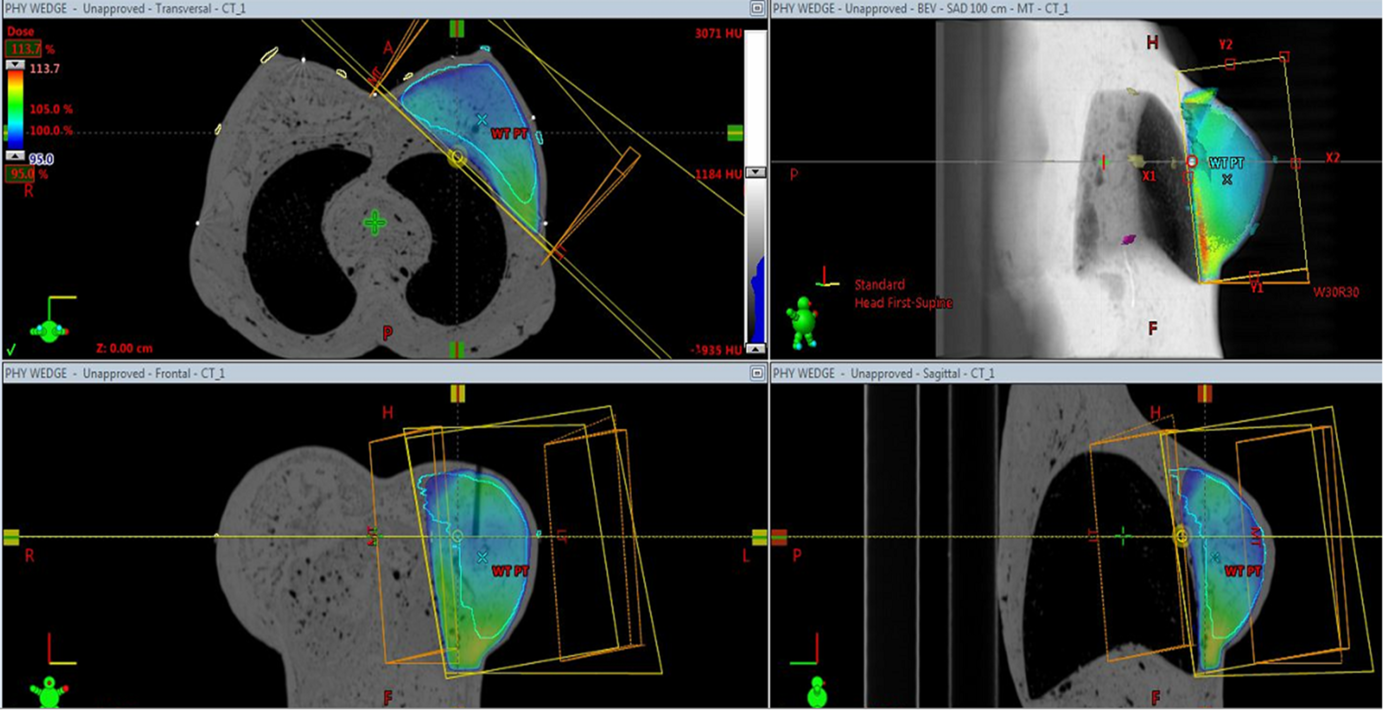
Figure 3. Dose distribution in the phantom (95% isodose) using CW technique to treat the left breast of the breast phantom.
Field-in-field technique (FiF)
The FiF plan consisted of two open tangential fields (with same gantry angles) with two or more shielded beams with MLC to reduce volumes of high dose within the PTV. In this technique, equal weights were assigned to the two open fields initially, and the dose distributions were calculated. Subfields with MLC shielding were added to reduce regions of hot spots, and relative beam weights were adjusted without compromising the PTV coverage.
ISC-based plan
The ISC is an electronic compensator and also a kind of forward planning IMRT. It involves beam modulation using dynamic MLC instead of physical compensators. The penetration depth determines the path length between the entry point and the compensation surface along each fan line of the beam. For example, a penetration depth of 50% creates a compensation surface that represents the midpoint of every ray. Reference Remouchamps, Huyskens and Mertens16 The Dose-Volume Optimizer algorithm modulates the intensity of each beamlet to achieve a uniform dose at the level of the compensation surface, taking into account the beam divergence and tissue inhomogeneities.
Intensity-modulated radiotherapy
In IMRT, four static tangential fields with gantry angle 310°, 140°, 340° and 110° (with collimator angles 5° and 355° were used. The width and height of the fields were adjusted with reference to the beam’s eye view (BEV) display to cover the PTV adequately. No plan normalisation was used in IMRT and RA plans. The dose prescription was the same as in CW, FiF and ISC plans. All IMRT plans were inversely optimised with direct machine parameter optimisation. Dose criteria for the PTV and Organs at Risks (OARs) were selected from the Radiation Therapy Oncology Group protocols 17 and also based on literature reviews.
RA technique
Two partial arcs ranging from gantry angles 310°–140° in both clockwise and anticlockwise directions were used with collimator angles of 15 and 45° for generating RA plans. The PTV coverage in BEV was ensured by opening the jaws within the allowed limits. For Volumetric Modulated Arc Therapy optimisation, the Progressive Resolution Optimizer V.11.0.31 was used. All the gantry angles used in the different plans studied, started from the same medial angle and lateral angles to avoid any influence on measured dose due to the placement of fields.
OSLD measurements in the breast phantom
The different treatment plans were executed in the machine with the OSLDs placed on both the breasts of the phantom. For all the treatment techniques, OSLD measurements were done three times on different days of the week (by executing three fractions), and the average of the measurements was taken and tabulated. The TPS calculated mean doses were noted for the 10 OSLDs (left superior (LS), left inferior (LI), left lateral (LL), left medial (LM), left nipple (LN) and right superior (RS), right inferior (RI), right lateral (RL), right medial (RM), right nipple (RN)) per fraction for various treatment techniques. The OSLDs were read three times, and the average of the three readings was taken to derive the measured dose. The deviation between measured and TPS dose at the surface of both breasts was calculated for all the treatment techniques.
Ionisation chamber measurements in the breast phantom
The measured doses using A-14 ion chamber were obtained by executing all the treatment plans for a single fraction and was compared with the corresponding calculated mean doses for the chamber volume from TPS. The deviation between measured and TPS calculated dose was calculated as
 $$\[{\rm{Deviation\ (\% )}}\,{\rm{ = }}\,\frac{{{({\rm{Measured}}\,\,{\rm{dose}} - {\rm{TPS}}\,\,{\rm{dose}})}}\over{{{\rm{Measured}}\,\,{\rm{dose}}}}}*100\]\[\]$$
Results
The results show that the OSLD measured dose and TPS dose for the point LM on PTV breast are the lowest (119·82 versus 127·8 cGy). At this location, the incident beam angle is almost normal compared to all other locations where the angle of incidence varies between 45° and 70° (Table 1). At all other locations where the angle of incidence increases, the measured as well as TPS values were larger (varied from 127·74 versus 127·20 cGy to 150·67 versus 148·5 cGy). The maximum measured dose on the CB with CW plan was 81·13 cGy, and the TPS calculated dose was 62·1 cGy at location RM. The maximum deviation between measured and calculated dose was found at the location RL, which is at the farthest distance (12·5 cm) from the nearest field border. With CW technique, the measured surface dose (mean) inside the treatment field was 136·23 cGy (68·1%), and TPS calculated dose (mean) was 138·12 cGy (69%), respectively. All values are compared after taking average of all the measurements. The measured dose (mean) to opposite breast was 13·3% and TPS dose was 11% of the prescribed dose.
Table 1. Deviation between measured doses and TPS calculated dose at the surface of the breast phantom using different planning techniques for a prescribed dose of 200 cGy

Abbreviations: MT, medial tangent; LT, lateral tangent; Dev, deviation between calculated and measured dose; SD, standard deviation.
Compared to CW technique, the FiF technique delivered less dose to all points on the CB. With this technique also, for the treated breast, the results show that the OSLD measured dose and TPS dose for the point LM are the lowest compared to all other locations. The TPS estimated zero dose at location RL, whereas measured dose was 5·06 cGy. With FiF technique, the dose to skin of the CB was 10·6% versus 8·8% (measured versus TPS) and the dose to skin of PTV breast was 67·2% versus 66·8% (measured versus TPS) of the prescribed dose. With ISC technique, the maximum measured dose on the CB was 50·5 cGy (RM) and the TPS calculated dose was 26·8 cGy. Compared to CW and FiF techniques, ISC technique delivered fewer doses to all points on the CB (Table 1). However, the effect of the increase in surface dose with increase in angle of incidence was not found in the measured dose using this technique. This shows that ISC technique, even though it is a 3DCRT technique, is capable of producing a uniform surface dose irrespective of the contour irregularities of the breast by compensating for variations in the target shape and density with the help of dynamic MLC. The mean dose to the skin of the CB was 7·6% versus 5·3% (measured versus TPS), and the mean dose to skin of PTV breast was 57% versus 53% (measured versus TPS) of the prescribed dose.
Using IMRT technique, the maximum measured dose on the CB was 62·15 cGy and the TPS calculated dose was 45·2 cGy (RM). Compared to all the above three techniques, IMRT technique delivered higher surface doses to all points on the CB except at location RM, where the dose was highest in CW technique. In this study also, for the treated breast, the results show that the large increase in surface dose was not found at locations (LS, LI, LN and LL) where the angle of incidence changed from 0° incidence. The results show that IMRT technique also achieved a uniform surface dose to the treated breast despite having surface contour irregularities and variation in beam incidence angle. With this technique, the mean dose to the skin of the CB was 13·5% versus 10·5% (measured versus TPS), and the mean dose to skin of PTV breast was 50% versus 46·8% (measured versus TPS) of the prescribed dose. The OSLD measured dose to the CB was higher in IMRT technique (mean = 13·5%) when compared to all other techniques studied. Compared to IMRT technique, RA technique delivered lesser surface doses to all points on the CB except at location RL. In this study also, for the treated breast, the results show that the large increase in surface dose was not found at locations where the angle of incidence varied from 0° to 45–60°. The results of OSLD measurements thus showed that ISC, IMRT and RA techniques delivered a uniform surface dose to the treated breast with the help of intensity modulation irrespective of the surface contour irregularities and variation in beam incidence angle. The dose estimated by TPS was better at location RL for RA technique compared to all other techniques. At this location, the TPS estimated 7·0 cGy, whereas the measured dose was 10·95 cGy. This might be due to the increased dose delivered to the phantom due to the continuous rotation of the gantry during treatment in the arc mode. With RA technique, the mean dose to the skin of the CB was 10·9% versus 9·13% (measured versus TPS), and the mean dose to skin of PTV breast was 50% versus 45·0% (measured versus TPS) of the prescribed dose. Concerning the results, the ISC, IMRT and RA techniques delivered less surface dose to PTV breast compared to CW and FiF techniques.
The results of ion chamber measurements at the centre of the PTV breast of the phantom are given in Table 2. For all the techniques studied and compared, while the TPS dose was always slightly more than the measured dose, the dose estimation accuracy of the TPS at the centre of the breast was found satisfactory. The maximum deviation between TPS calculated and measured dose was 3·2% and the minimum deviation was 0·24%.
Table 2. Deviation between measured dose and TPS calculated mean chamber doses at the centre of the PTV breast of the phantom using A-14 chamber

Discussion
The surface dose measured for PTV breast and CB showed significant difference with the different treatment techniques, which are consistent with earlier studies. Reference Al-Rahbi, Ravichandran, Binukumar, Davis, Satyapal and Al-Mandhari3,Reference Quach, Morales, Butson, Rosenfeld and Metcalfe18,Reference Nakano, Hill, Whitaker, Kim and Kuncic19 Concerning the results, it is seen that the dose to the CB is lowest in ISC technique and greatest in IMRT technique. The CW technique also delivered a dose comparable to IMRT technique to the CB of the phantom. The dose to the surface of PTV breast was highest and comparable in CW plans and FiF plans (68% and 67%) and lowest in IMRT and RA plans (50% each). The increase in the CB dose in CW plans is undoubtedly due to the increased scatter from the metal wedge placed in the path of the beam. When compared between IMRT and RA, the IMRT technique delivered the maximum dose to the point RM on the CB of the phantom. This might be due to (1) the increased monitor unit (MU) with IMRT technique compared to RA and (2) the possible exit dose from the two angulated lateral beams (G-110 deg and G-140 deg). The RA technique delivered the minimum dose to point RM followed by ISC technique. But when the average surface dose values measured on the CB using OSLDs were compared between techniques, the ISC technique showed the lowest values (7·5%), and IMRT and CW technique showed the maximum values (13·5% and 13·3%). FiF and RA technique produced comparatively lesser dose to the surface of CB (10·7% and 10·9%). Considering the results, it can be concluded that IMRT and CW technique delivered higher doses to the surface of the CB and ISC followed by FiF technique delivered the lowest doses. The results of our phantom study showed that CW, IMRT and RA techniques are not suitable options while planning radiotherapy for breast due to the increased dose to the CB.
The techniques ISC, IMRT and RA techniques did not show any increase in the surface dose with increase in the beam incidence angle and surface contour irregularities. This confirms that these techniques could achieve a uniform dose distribution in the surface of breast with the help of intensity modulation using MLCs. Moreover, in CW, FiF and ISC plans, the dose is normalised to a point at the mid plane of the breast, whereas in IMRT and RA plans, the dose is normalised to the volume of PTV. Even though the normalisation of dose was at a point in ISC plans, they produced a uniform surface dose irrespective of the contour irregularities of the breast by compensating for variations in the target shape with the help of dynamic MLC. For IMRT and RA plans, a reduction in the measured surface dose of PTV breast was observed (50%) compared to other plans. Akino et al. measured the surface doses of the breast using Gafchromic films and reported that the surface received approximately 45–50% of the absorbed dose in IMRT plans. Reference Akino, Das, Bartlett, Zhang, Thompson and Zook20 They also reported an increased value of 70–75% in the lateral points of the breast.
This is because while planning IMRT and RA techniques, the skin is configured as an OAR after cropping from the PTV breast. By doing so, the surface dose significantly reduced by about 18%, without compromising PTV coverage. Al Rahbi et al. used Thermo luminescent Dosimeters (TLDs) to measure surface doses on an anthropomorphic phantom and reported a reduction in PTV skin dose by 20% in IMRT plans. Reference Al-Rahbi, Ravichandran, Binukumar, Davis, Satyapal and Al-Mandhari3 Almberg et al. also reported that seven-field IMRT showed a reduction of surface dose compared to tangential wedged fields. Reference Almberg, Tore and Jomar21 Their study also reported that the surface dose is between 15% and 55% of the target dose with seven-field IMRT plan. Whether the skin should receive dose or not depends on the infiltration of the tumour into the skin. Several authors reported that the cosmetic outcome for patients undergoing breast radiotherapy depends on the treatment technique adopted in delivering the dose, and therefore, the above results assume clinical significance.
The results of our study showed dose values varying from 50 to 68% of the prescribed dose at the surface of the treated breast using OSLD for the different techniques studied. Williams et al. investigated the CB Dose on the CT scans of an anthropomorphic phantom. Reference Williams, Moran and Hsu22 They concluded that external wedges resulted in highest CB dose compared to open tangents and segmental IMRT plans. They recommended that to obtain the desired homogeneity to the treated breast while minimising CB dose, segmental and IMRT techniques should be encouraged over external physical wedges. Bhatnagar et al. measured and reported that there is a significant reduction in the mean dose to the CB using IMRT compared to 3-D technique. Reference Bhatnagar, Brandner and Sonnik23 But, the results of our study showed that the surface dose to the CB was highest for IMRT technique followed by CW technique with 30° physical wedge when compared to all other techniques studied.
However, many studies reported that the mean doses to the heart, both lungs and CB from multi-field IMRT are considerably larger than from conventional tangential techniques. Reference Al-Rahbi, Al Mandhari and Ravichandran4,Reference Kundrát, Remmele and Rennau24 Nakano et al. suggested that even though IMRT achieves a homogeneous distribution in tumour sparing normal tissues, it increases the potential to cause radiation-induced second cancers. Reference Nakano, Hill, Whitaker, Kim and Kuncic19 Since IMRT involves more number of treatment fields, a larger volume of healthy tissue is exposed to low dose of radiation. Some others have reported that IMRT to the whole breast results in a significant decrease in acute dermatitis, edema, and hyperpigmentation of the skin compared to the CW technique. Reference Harsolia, Kestin and Grills25,Reference Fong, Bromley, Beat, Vien, Dineley and Morgan26 So it is imperative to plan radiotherapy in carcinoma breast patients using suitable techniques to achieve better tumour control and minimise the complications that may develop in crtical organs. But most of the results are all based on purely dosimetric studies, and one cannot rely only on the TPS to conclude which technique is better. The results should be based on measurements in phantoms using suitable dosimeters. Discrepancies may arise in the surface and build-up region between the TPS prediction and measurement. However, proper calibration and appropriate selection of dosimeters will help to improve the accuracy of these measurements and will help us to report the results with confidence.
Our study was based on the measurements in a breast phantom to determine which treatment technique delivers the minimum dose to the surfaces of CB. The phantom study showed that the ISC technique delivered the lowest dose to the CB. The MU required to deliver the same prescribed dose was lowest for FiF plans compared to all other techniques studied. This may help to reduce the treatment time, and since no external beam-modifying devices need to be placed in this technique, the treatment execution time is also considerably reduced thereby treating more number of patients in a busy set-up. CW and IMRT techniques showed comparable values of (13·5% and 13·3%) mean doses to the surface of CB. Considering the results of the dosimetric studies and phantom measurements, it can be concluded that the FiF technique and ISC techniques are preferred while planning breast radiotherapy.
Conclusion
The phantom study showed that the mean value of dose to the CB was lowest with ISC technique (7·5%) and FiF technique (10·1%). IMRT technique delivered the maximum value of 13·5% followed by CW technique 13·3%. The MU required to deliver the same prescribed dose was lowest for FiF plans compared to all other techniques studied. This may help to reduce the treatment time, and hence no external beam-modifying devices need to be placed in this technique, and the treatment execution time is also considerably reduced thereby treating more number of patients in a busy set-up. With reference to the results of the phantom measurements, it can be concluded that the FiF and ISC techniques are preferred while planning breast radiotherapy. During the planning of whole breast radiotherapy, even if a wedge plan is the choice, a plan with an enhanced dynamic wedge (EDW) ought to be used as the dose to the peripheral regions is greatly reduced with the use of an EDW as reported by our study. Reference Gopalakrishnan, Nair, Raghukumar, Menon and Bhasi15
Acknowledgements
None.


