


I. INTRODUCTION
Miniaturization of any device always reflects scientific progress. As there is an increase in demand of wireless services such as WiMAX, WLAN, Wi-Fi, Bluetooth, PCS, DCS, GPS, 3G, and 4G, the available radio spectrum is decreasing day by day. Hence there is a need of multifunctional antennas because it is not possible to dedicate single antenna for each of these services and also to reduce the complexity and size of the given wireless system. The purpose of multifunctionality is fulfilled by reconfigurable antennas. These antennas can change their operating frequency, impedance bandwidths (BWs), polarization, and patterns independently according to changing operating requirements of a given radio system. Accordingly, these are categorized into frequency diversity, polarization diversity, and pattern diversity reconfigurable antennas.
Due to their many advantages such as integration density, multiple functionality, reconfigurable capability, less cost, and miniaturized size, reconfigurable antennas attract military applications besides commercial ones. According to the design requirements and desired antenna performance, one among the different reconfiguration methods such as altering the physical structure of the antenna, changing feeding methods or implementing arrays, etc. can be chosen. This can be done through switching, material tuning, structural modifications, etc. The switching technology uses solid-state switches field effect transistors (FETs), varactor or P-Intrinsic-N (PIN) diodes) or monolithic integrable surface micromachined radio frequency (RF)-micro-electro mechanical systems (MEMS) switches.
Lot of research has been made on reconfigurable antennas in the past, many latest researches use advanced reconfiguration mechanisms such as using metasurfaces (MS) [Reference Kelley3–Reference Jalali Mazlouman, Mahanfar, Soleimani, Chan, Menon and Vaughan4], in which planar MS placed atop of and in direct contact with a planar slot antenna, both having a circular shape. By rotating the MS around the center with respect to the slot antenna, it can be reconfigured to different frequencies [Reference Kelley3] and different polarizations linear polarization (LP), right hand circular polarization (RHCP), left hand circular polarization (LHCP) [Reference Jalali Mazlouman, Mahanfar, Soleimani, Chan, Menon and Vaughan4], using liquid metal (EGaIn) as switching mechanism enables the pressure-driven displacement of a low-loss dielectric fluid and the liquid metal from a reservoir atop the patch to switch between the different antenna states [Reference Zhang, Wu and Denidni5], a pattern reconfigurable antenna has parasitic elements that rotates around a fixed monopole element on a ground plane to attain rotated patterns for diversity. This rotation is based on electro active polymer [Reference Genovesi, Di Candia and Monorchio6], electronically beam steerable antenna system using active frequency-selective surfaces [Reference Chang, Lai, Cheng and Hsue7]. A frequency agile antenna is proposed for software defined radio application in [Reference Qin, Guo and Ding8] where in frequency reconfigurability is achieved by activating four groups of PIN diodes that connects central patch to four different peripheral patches that provides 24 = 16 reconfiguring states. A symmetrical multipolarized circular patch antenna that generates six LPs at 30° interval using 12 p–i–n diodes placed across a circular ring slot on the patch is proposed in [Reference Jusoh, Sabapathy, Jamlos and Kamarudin9], an aperture-fed polarization reconfigurable antenna that switches between horizontal, vertical, and 45° linear polarizations in dual bands is proposed in [Reference Sulakshana and Anjaneyulu10]. A very high-gain beam switching antenna that can steer beam in five directions in both azimuth and elevation planes using four parasitic patches for WiMAX applications is proposed in [Reference Sulakshana and Anjaneyulu11].
More complex in terms of structure and number of switches, large dimensions, more than one layer and use of parasitic elements, less impedance BW (<20%), feed radiation, and less efficiency due to conventional micro strip feeding mechanism are some limitations observed in the reconfigurable antennas mentioned above. In this work, simple, small, and thin wideband reconfigurable antennas are evaluated with independent control of operating frequency, polarization, and radiation patterns for improved performance of wireless systems.
In this paper, a study of different reconfigurable antenna designs for frequency, polarization, and pattern diversities is made. Switches are used to obtain reconfigurability. The prototypes of the respective antennas were fabricated and tested. Starting with frequency reconfigurability in Section II, a simple and compact E-shaped antenna with two switches was designed to operate at four frequencies serving four different applications. In Section III, rectangular- and circular-shaped patch antenna designs and their principle of operation for polarization selectivity are discussed. Section IV presents, a pattern reconfigurable antenna with multiport excitation without using any switches. In all the cases, the coplanar waveguide (CPW) feeding technique is used to get enhanced operating BW and the experimental results are compared with simulated ones in [Reference Sulakshana and Anjaneyulu12–14]. Finally, conclusions and possible applications were discussed in the last section.
II. FREQUENCY RECONFIGURABLE E-SHAPED ANTENNA
The geometry of the proposed E-shaped reconfigurable antenna is shown in Fig. 1. The antenna is etched on a single layer of low-cost FR4 (ε r = 4.3) dielectric substrate which is 35 × 30 mm2 in dimension. Two switches S 1 and S 2 are incorporated in the main structure to redirect the current in certain directions so as to change the effective electrical length of the antenna which in turn is responsible for changing operating frequencies. These switches are used to connect two rectangular patch lines in the E-structure to operate the antenna in four different operating modes as given in Table 1.

Fig. 1. Geometry of the proposed frequency reconfigurable antenna. The parameters of the antenna are L 1 = 15.3, W 1 = 5.0, L 2 = 3.6, W 2 = 2.0, L 3 = 12.0, W 3 = 8.0, W 4 = W 6 = W 8 = 2.0, W 5 = W 7 = 1.0, L = 35.0, W = 30.0, g = 0.4, and t = 1.6. All dimensions are in mm.
Table 1. Measured versus simulated results of frequency reconfigurable antenna.

* The values within braces indicate measured results.
The ON and OFF conditions of switches are realized by forward and reverse biasing of PIN diodes. Ideally, when a forward bias is applied to make the switch ON, the switch would have low impedance characteristic, acts as short and the current can flow through the diode. On the other hand, when a reverse bias is applied to make the switch OFF, the switch exhibits high impedance characteristic and acts as open circuit which implies that there is no connection. These two switches in the simulation are realized as short copper paths. Presence of the path is treated as ON and absence as OFF. The measured and simulated S-parameters of all the switch configurations are shown in Fig. 2. When both the switches are OFF, the antenna resonates at a single resonant frequency of 5.8 GHz which suits for IEEE 802.11a WLAN (5.725–5.875 GHz) applications. When either of the switches is ON, it is observed that the antenna resonates at two operating bands, among them one is in C-band and another one is in X-band. The simulations were carried out on commercially available electromagnetic simulator Integral Equation 3-Dimension (IE3D) by Mentor Graphics. The detailed simulated and measured parameters are listed in Table 1.
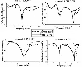
Fig. 2. Measured and simulated reflection coefficients curves of the frequency reconfigurable antenna.
The measured radiation patterns in the azimuth (x−y) plane and elevation (x−z & y−z) planes for all the switch combinations are shown in Fig. 3. The measured gain of all the operating modes of the antenna are shown in Fig. 4. The antenna has a gain of above 2 dBi for all the operating modes and VSWR close to the value one.

Fig. 3. Measured radiation patterns in azimuth and elevation planes with co and cross-polarizations of frequency reconfigurable antenna.
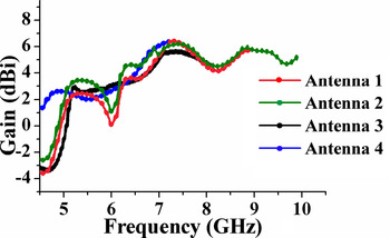
Fig. 4. Measured gain of the proposed frequency reconfigurable antenna.
III. POLARIZATION RECONFIGURABLE ANTENNAS
A) Rectangular antenna for polarization diversity
The first structure of the polarization reconfigurable antenna is shown in Fig. 5. The antenna is designed and prototype of the same is fabricated on the FR4 substrate of thickness 3.2 mm whose dielectric constant is ε r = 4.4. The basic structure consists of a rectangular patch of length 10 mm and width 15 mm. The structure of the basic patch is modified by introducing two rectangular strips of 0.5 mm × 15 mm dimension on both sides of the main radiating patch, in order to achieve circular polarization (CP). These strips are connected through two switches namely S 1 and S 2 to the main patch. By making two switches ON/OFF, the polarization of the antenna can be changed from vertical linear to circular (RHCP, LHCP). Different reconfiguring cases of the antenna are given in Table 2.

Fig. 5. Geometry of the rectangular polarization reconfigurable antenna. The parameters of the antenna are L 1 = 10, W 1 = 15, L 2 = 3.6, W 2 = 7.0, L 3 = 15.3, W 3 = 6.0, g 1 = 0.4, g 2 = 0.5, g = 0.5, L = 35.0, W = 30.0, and t = 3.0. All dimensions are in mm.
Table 2. Simulated versus measured results of rectangular polarization reconfigurable antenna.

* The values within braces indicate measured results.
The antenna is designed and simulations were carried out on popular Mentor Graphics electromagnetic simulator IE3D that employs Method of Moments (MoM) technique. For reconfigurable operation, in Case 1, when both the switches are in OFF state, the antenna exhibits linear polarization because of the symmetry in the antenna structure. In Case 2, when S 1 is OFF and S 2 is ON, due to the quasi-symmetric structural configuration, two orthogonal degenerate modes are generated which makes the antenna to excite in CP. Thus when the antenna is reconfigured from Cases 1 to 2, the polarization switches from linear to circular. The current distributions of the reconfigurable antenna in case 3 when S 1 is ON and S 2 is OFF are shown in Fig. 6.

Fig. 6. Surface electric current distribution of the proposed antenna in Case 3 at each quarter interval.
This figure clearly shows the rotation of current vector in the clockwise direction at the position of switch S 1 at time instances t = 0, t = T/4, t = T/2, and t = 3T/4, where T is the time period of the RF excitation signal. This implies antenna operates in LHCP. Similarly in Case 2, it exhibits RHCP. In Case 4, the antenna radiates through center rectangular patch in linear polarization. The measured and simulated return loss curves of all the operating modes of the antenna are shown in Fig. 7. When the switches S 1 and S 2 are OFF, the electrical length of the antenna is small and hence the antenna resonates at high frequency (f h ) (5.0 GHz). When both switches are ON, the effective electrical length is large and the antenna resonates at low frequency (f l) (4.4 GHz) and when one of the switches is ON and the other is OFF, the relation between the frequency of operation is f l < f (4.7 GHz) < f h . The given antenna has same frequency characteristics when operating in two polarization diversity modes. The measured and calculated antenna parameters of the proposed antenna are summarized in Table 2. The measured radiation characteristics of the antenna are shown in Fig. 8, and measured gain, axial ratio curves are shown in Fig. 9.

Fig. 7. Reflection coefficient (S 11) curves of the proposed rectangular polarization reconfigurable antenna in different operating modes.

Fig. 8. Measured radiation patterns in azimuth and elevation planes with co and cross-polarizations of rectangular polarization reconfigurable antenna.

Fig. 9. (a) Measured axial ratio and (b) measured gain of rectangular polarization reconfigurable antenna.
B) Circular-shaped antenna for polarization diversity
A circular-shaped antenna is proposed for polarization reconfiguration, which is designed on a very thin Rogers RT/Duroid 5880 substrate with a thickness of 0.254 mm and having dielectric constant of 2.2 as shown in Fig. 10. The radius of the circular patch is 6 mm which is fed by CPW feed. The CP effect in the basic patch is introduced by cutting the original circular patch at 2.0 mm distance from two sides of horizontal diametric edges. These left out patches are connected to the main patch through switches S 1 and S 2. The four fundamental modes of operations of the proposed antenna are given in Table 3. For the case of basic circular patch without switches, the fundamental mode TM11 is excited. By introducing switches in the antenna to accommodate the CP effect, the surface current path gets modified and the fundamental mode TM11 splits into two near degenerate resonant modes.

Fig. 10. Geometry of the circular polarization reconfigurable antenna. The parameters of the antenna are L 1 = 15.3, L 2 = 3.6, W 1 = 30, W 2 = 7, h = 0.254, g 1 = 0.5, d = 2.0, g = 0.4, and r = 6.0. All dimensions are in mm.
Table 3. Simulated versus measured results of circular polarization reconfigurable antenna.

* The values within braces indicate measured results.
The antenna in mode 1, when both switches are OFF, generates vertical LP and resonates at 2.9 GHz. In mode 2, when S 1 is ON and S 2 is OFF, due to the quasi-symmetrical structure, the slot near the left edge of the circular patch perturbs the current by changing the length of the surface current vector in the x-direction without affecting current vector directed along the y-direction. This makes the fundamental mode TM11 split into two orthogonal degenerate modes with equal amplitude and 90° phase shift and the instantaneous surface current vector on the circular patch rotates and thus the radiated field is circularly polarized. The direction of the current vector is counter clockwise hence the antenna has the RHCP pattern. Similarly, when the antenna operates in mode 3, i.e. when S 1 is OFF and S 2 is ON, the slot near the right edge of the patch changes the current perturbation and the two degenerated orthogonal modes have equal amplitude and −90° phase shift, which make the surface current vector rotate in the clockwise direction producing the LHCP pattern. Figure 11 shows the surface current distributions on the circular patch in mode 3, at the switch S 2 at time instances t = 0, T/4, T/2, and 3T/4.

Fig. 11. Surface electric current distribution of the proposed antenna in Case 3.
The prototype of the proposed reconfigurable antenna is fabricated and tested in anechoic chamber. The simulated and measured return loss, radiation patterns in the E θ elevation and E ϕ azimuth planes for each operating mode are shown in Figs 12 and 13, respectively. It shows that the antenna when operated in mode 1, resonates at 2.7 GHz. Since both the switches are OFF, its electrical length is small compared with other three cases and hence it resonates at higher frequency. In mode 4, the electrical length of the antenna is large compared with other cases; hence it resonates at lower frequency of 2.38 GHz. When the antenna operates in modes 2 and 3, i.e. when one of the switches is ON, asymmetry is created in structure and this creates little perturbation of the fundamental mode TM11 and hence the resonant frequency is slightly increased to 2.45 GHz. The measured gain and axial ratio curves are shown in Fig. 14, respectively. Table 3 summarizes all the measured and simulated results.
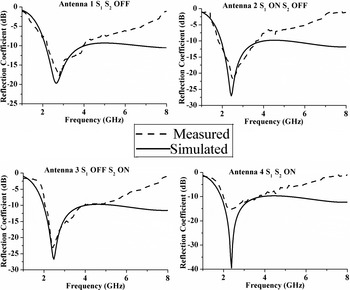
Fig. 12. Reflection coefficient (S 11) of the circular shaped reconfigurable antenna.

Fig. 13. Radiation patterns of the antenna in E θ and E ϕ planes with co- and cross-polarization.

Fig. 14. (a) Measured axial ratio and (b) measured gain of CP reconfigurable antenna.
IV. PATTERN RECONFIGURABLE ANTENNA
A very simple, compact, and wideband pattern diversity antenna with multiport excitation is designed and analyzed. Instead of using switches for reconfiguration, four ports are used to excite the basic patch one at a time, where the pattern changes its direction to 90° with each individual port exciting the main radiating patch. The geometry of the proposed antenna is shown in Fig. 15. The antenna is simulated on a 1.6 mm thick low-cost FR4 substrate whose dielectric constant is 4.4 with loss tangent 0.02. The radius of basic circular patch is 2.5 mm. The size of the antenna is 14 mm × 13 mm × 1.6 mm which is very compact. The simulator tool used here is Ansoft High-Frequency Structure Simulator which employs finite element method numerical technique for solving three-dimensional (3D) electromagnetic (Em) problems. The signal is fed through the four ports, independently, which are placed at the four sides of the basic rectangular patch. When the patch is fed by one port, all the remaining ports are terminated by a 50 Ω load for proper impedance match. The signal fed through each individual port changes the spatial current distribution on the radiating patch and thus changes the radiation pattern.

Fig. 15. Geometry of the proposed pattern reconfigurable antenna L = 14 mm, W = 13.8 mm, t = 1.6 mm, g = 0.3 mm, L 1 = 6.05 mm, W 1 = 5.95 mm, L 2 = 1.3 mm, W 2 = 4.5 mm, L 3 = 4 mm, W 3 = 1.95 mm, and r = 2.5 mm.
The simulated S 11 (in dB) curves are shown in Fig. 16 for all the operating modes when the antenna is fed through four ports individually. The operating frequency of the antenna when it is fed through port 1 is 26.7 GHz with −10 dB impedance BW of 12.2 GHz (46.8%), through port 2 it has same frequency characteristics as the antenna fed through port 1. Through port 3 it is 27.5 GHz with a BW of 11.15 GHz (40.64%) and through port 4 it has same frequency characteristics as the antenna fed through port 3. The radiation characteristics of the basic circular patch are determined by the electric or magnetic current distribution on the radiating structure which in turn are responsible for changing frequency characteristics. Because of this relationship between the source currents and the resulting radiation, it is difficult to achieve pattern reconfigurability without having many changes in frequency characteristics. Hence there is a slight change in frequency in each operating mode.

Fig. 16. Reflection coefficient (S 11) curves of the pattern reconfigurable antenna operating in four different modes.
The 3D and two-dimensional (2D) plots of the radiation patterns of the antenna operating in four different modes are shown in Figs 17 and 18. It is observed that when the antenna feed is changed from ports 1 to 3, ports 3 to 2, ports 2 to 4, and again to port 1, the radiation pattern changes by 90° each time.

Fig. 17. 3D radiation patterns of the proposed pattern reconfigurable antenna.

Fig. 18. (a) 2D radiation patterns of the pattern reconfigurable antenna in azimuth plane with different ports of excitation. (b) 2D radiation patterns of the pattern reconfigurable antenna in elevation plane with different ports of excitation.
It is observed from the above figures that frequency characteristics are maintained, while changing the radiating characteristics when the antenna is fed through different ports individually which satisfies the principle of pattern reconfigurability. The transmission coefficients of the antenna when fed through port 1 are shown in Fig. 19. It is known that S ij = S ji and here in this case S 12 = S 34. Also, S 31 = S 41 = S 32 = S 42. We can say that, when the antenna is fed through any one port there is more chance of the signal getting leaked in the adjacent ports.

Fig. 19. Transmission coefficients of the proposed antenna when fed through port 1.
The average correlation between the total power radiated by antenna when fed through different ports within the 3D space, called envelope correlation coefficient envelope correlation coefficient (ECC) is calculated to evaluate the diversity performance [15]. This is calculated from S-parameters obtained in the simulations using the formula (1). A good diversity performing antenna has the correlation factor <0.5. The correlation between the ports 1 and 2 is given by equation (1). It is known that, ρ ij = ρ ji , and also in our case ρ 31 = ρ 41, because of the equal length of the two vertical sides of the rectangle. Figure 20 shows the ECCs obtained from the simulated S-parameters:
 $$\rho _{12} = \displaystyle{{\vert S_{11} \times S_{12} + S_{21} \times S_{22} \vert^2} \over {(1 - (\vert S_{11} \vert^2 + \vert S_{21} \vert^2 ))(1 - (\vert S_{22} \vert^2 + \vert S_{12} \vert^2 ))}}.$$

Fig. 20. Simulated envelope correlations (ECs) of the proposed antenna.
The ECC for ρ 21 is <0.07 and for ρ 31 is <0.06 which satisfies the low correlation criteria of ECC < 0.5. Hence the designed antenna has a very good diversity performance.
V. CONCLUSION
A study on frequency, polarization, and pattern diversity reconfigurable antennas is presented in this paper. The antennas are implemented on very simple and compact structures in order to satisfy several wireless applications. The CPW feeding technique is used for all the antennas to attain wide BWs. A frequency reconfigurable antenna is designed with two switches which operate at four different operating bands. This antenna can be used in WLAN (5.15–5.35) GHz, HIPERLAN 2 (5.47–5.725) GHz, and WLAN (5.725–5.875) GHz applications. Two polarization selective antennas are designed operating at 5.8 and 2.4 GHz with polarization reconfigurations from vertical LP to RHCP and LHCP. The first polarization selective antenna can be used in Wi-Fi 802.11a (5.0 GHz), WLAN (5.47–5.75) GHz applications and the second one can be used in Bluetooth 2.45 GHz applications. The prototypes of all the three antennas are fabricated and tested and the measured results are found in good agreement with simulated ones. In all the above three cases, the measured results are slightly deviated from simulated ones. The reasons for the difference between simulated and measured results are due to minor fabrication inaccuracies, dielectric imperfections, and SubMiniature Version A (SMA) connector solder losses (i.e. while testing, SMA connector can be treated as the extension of the ground which creates some impedance mismatch at the CPW feed). Finally, a pattern reconfigurable antenna with multiport excitation is proposed which operated in K-band. The antenna is capable of rotating its radiation pattern by 90° with each port excitation without having major changes in frequency characteristics. A very low ECC is obtained between four ports which can be used in different multiple input multiple output (MIMO) applications. Due to its compact dimension and high isolation between the different ports and wide BW, the proposed antenna is suitable for mobile satellite communication applications operated under K-band.
ACKNOWLEDGEMENTS
The authors acknowledge NIT Warangal for providing research facilities and also acknowledge Research Centre Imarat (RCI-DRDO), Hyderabad, India for providing measurement facilities.
 Chilukuri Sulakshana was born in Hyderabad, India in 1985. She received her B.Tech. degree (2007) in ECE, M.Tech. (2010) in Communication Systems (ECE), and currently pursuing Ph.D. degree from National Institute of Technology, Warangal, India. Her field of study is reconfigurable antennas and other areas of interest are microwave engineering and antenna wave propagation. She has publications in five international journals, eight international conferences, and one national conference.
 Lokam Anjaneyulu was born in 1967 in India. He obtained his B.Tech. (ECE) in 1989, M.Tech. in 1991, and Ph.D. in 2010 from National Institute of Technology, Warangal, India. He worked as a Project Officer at the Institute of Armament Technology, Pune, India for 5 years from 1991 and involved in the design of surface-borne and air-borne radar systems for clutter measurement application. Later, he worked as a Staff Scientist at Helios Systems, Madras, India for 2 years and engaged in the development of radio wave propagation assessment software modules for ship-borne radars. He has been with the Department of ECE at National Institute of Technology, Warangal, India since 1997. His areas of interest include computer networks, electromagnetic field theory, microwave & radar engineering, and neural networks & fuzzy logic systems. He has completed few defence R&D projects and has 31 papers to his credit in national and international conferences and journals. He is a Life member of ISTE and a member of IEEE, IEEE Antennas, and Propagation Society, IEEE Signal Processing Society.


