


1. INTRODUCTION
Controlling the transport of relativistic electron beams (REB) in an inhomogeneous compressed plasma is a prerequisite for the success of the fast ignition (FI) scheme for inertial confinement fusion (Tabak et al., Reference Tabak, Hammer, Glinsky, Kruer, Wilks, Woodworth and Mason1994; Reference Tabak, Clark, Hatchett, Key, Lasinski, Snavely and Freeman2005; Batani, Reference Batani2002; Mulser & Bauer, Reference Mulser and Bauer2004; Atzeni & Tabak, Reference Atzeni and Tabak2005; Gus'Kov, Reference Gus'Kov2005; Badziak et al., Reference Badziak, Glowacz, Hora, Jablonski and Wolowski2006). In FI, a REB generated by the interaction of an intense ultra-short laser pulse should heat the compressed fuel core up to ignition temperature. In this respect, one of the main issues is how to get a good collimation of the REB. Unfortunately, experimental results show that usually the REB are characterized by a large spread (Martinolli et al., Reference Martinolli, Batani, Perelli-Cippo, Scianitti, Koenig, Santos and Cowan2002; Santos et al., Reference Santos, Amiranoff, Baton, Gremillet, Koenig, Martinolli and Hall2002; Stephens et al., Reference Stephens, Snavely, Aglitskiy, Amiranoff, Andersen, Batani and Scianitti2004; Martinolli et al., Reference Martinolli, Koenig, Amiranoff, Baton, Gremillet, Santos and Batani2004; Green et al., Reference Green, Ovchinnikov, Evans, Akli, Azechi, Beg and Norreys2008), which implies that its energy is dispersed into a too large region, or otherwise that the energy of the igniting beam should be increased to unrealistic values. The large spread angle could be compensated by self-generated magnetic fields. In this context several schemes have been proposed (Robinson et al., Reference Robinson, Sherlock and Norreys2008; Zhou et al., Reference Zhou, Wu, Cai, Chen, Cao, Wang and He2010; Chawla et al., Reference Chawla, Wei, Mishra, Akli, Chen, McLean and Beg2013; Gu et al., Reference Gu, Yu, Zhou, Wu, Wang, Liu and Zhang2013). In particular an experiment performed at the Rutherford Appleton Laboratory (RAL) with the Vulcan laser has shown that self-generated magnetic fields could act to collimate the beam (Pérez et al., Reference Pérez, Koenig, Batani, Baton, Beg, Benedetti and Volpe2009; Reference Pérez, Debayle, Honrubia, Koenig, Batani, Baton and Volpe2011).
Such strong magnetic fields are associated with electrical resistivity gradients created during the implosion of targets. These magnetic fields can deflect the electron beams towards higher resistivity regions and, if the time of target implosion is properly arranged, could guide the electron beam. In particular, at RAL, the optimum collimation was observed just before the rebound of shock at the central axis of cylinder, in good agreement with simulation results.
The motivation of the work described in this paper was to extend the results obtained at RAL to higher compression rate and larger dimensions by using a laser system with larger energy as Gekko XII at Institute of Laser Engineering (ILE; Osaka, JAPAN) to approach conditions closer to a realistic FI scenario, generating a large scale plasma using a kJ class laser.
Before the experiment, we performed simulations of nanosecond laser interaction with the target (Hallo et al., Reference Hallo, Olazabal-Loumé, Ribeyre, Dréan, Schurtz, Feugeas and Maire2009) in order to optimize irradiation uniformity using six laser beams. Such calculations justified the use of two-dimensional (2D) hydrodynamic simulations (Breil et al., Reference Breil, Galera and Maire2011), which were then used to predict the evolution of macroscopic parameters (temperature, density, etc.). Finally, in order to describe the interaction of fast electrons with the plasma we used a “reduced” kinetic model (Touati et al., Reference Touati, Feugeas, Nicolaï, Santos, Gremillet and Tikhonchuk2014). Indeed, the fast electrons, generated by the high-intensity laser beam, have a mean free path much longer than the characteristic plasma scale length. This implies that the usual implosion approximation for heat transport is not valid and shows the need for a kinetic treatment of electron transport. Unfortunately, kinetic treatments are computationally very heavy and their direct coupling to hydrodynamic codes is still prohibitive. Reduced kinetic models, instead, simulate the process at a reduced computational cost, therefore allowing direct coupling.
2. EXPERIMENTAL SET-UP
The compression phase is driven by laser beams with nanosecond pulses while the electron propagation phase is driven by a laser with a picosecond pulse. Thus in the experiment there are two different processes at two different temporal scales.
As described in Figure 1, we imploded the cylindrical target with 6 ns long pulses (LP), from the GEKKO XII laser. Each of them delivered about 300 J at 527 nm (2 ω of Nd laser) within a focal spot of ≈ 150 μm radius (half width half maximum) during 1.2 ns. Then, we generated the REB using the short pulse (SP) LFEX laser delivering up to 500 J within 2 ps at 1 ω (1.053 μm, an average intensity of ≈2 × 10¹⁹ W/cm2). As usual for this kind of lasers, the SP is associate to a prepulse: At the time of the experiment, such a foot had 2 ns duration and an intensity of 1012–1013 W/cm2. This foot arises from Amplified Optical Parametric Fluorescence from the amplifier chain of Laser for Fast ignition Experiment (LFEX).

Fig. 1. Detail of the cylindrical target structure and schematic of the experiment. On the left, the side-view showing the LFEX beam focused within the gold shield on the Ni foil and on the right, the 3D view. The ns-compression beams are spaced by 60° each in angle.
The delay between LP and SP laser beams could be varied to explore the propagation of fast electron beam at different compression conditions.
The details of target cylinders are shown in Figures 1 and 2. The hollow plastic cylinder is ≈ 400 μm long and 350 μm in diameter and was filled with plastic foam (with density 0.3 g/cm3). Both ends of the target cylinder were surrounded by a gold shield with thickness of 50 μm and were covered with a plastic layer in order to avoid strong X-ray emission from the ablated plasma. Nickel (Ni) plate and Copper (Cu) plate are placed at the front and at the back end of the target cylinder, with respect to REB propagation. Characteristic X-ray Kα emission from Ni and Cu were, respectively, used as measurement of the fast electron source and of the fast electron penetration through the compressed foam and up to the Cu foil. Moreover the plastic foam in the target was doped with deuterium (10% of weight). In this way we hoped to observe neutrons generated by D–D nuclear reactions and possibly using them as a diagnostic of ion temperature (and hence of the energy relaxation process from fast electrons to the background plasma ions).

Fig. 2. Photograph of the target cylinder: On the left, the side view and on the right, the front view (from the side of the Cu foil).
3. SIMULATIONS, IRRADIATION UNIFORMITY
As described in Figure 1, we imploded the cylindrical target with 6 ns-pulses (LP). The irradiation uniformity of the compression beams had been optimized by numerical simulations. Figure 3 shows the results of the optimization, normalized on single beam maximum intensity. Six beams were indeed sufficient to assure very good irradiation uniformity, as shown in Figure 3 (on the right). In order to improve the uniformity over the 200 μm long foam-filled cylinder, we needed to slightly shift the pointing of beams with respect to the half of the cylinder: Three beams were shifted towards the entrance end (Ni foil) and three beams to an offset of 40 μm to the opposite side (Cu foil). The level of uniformity obtained in the central 150 μm region is ΔI/I ≈ 44%.

Fig. 3. Simulation result provided for uniformity of long pulse Gekko irradiation on the target cylinder (simulations with the Code Ceclad, Hallo et al., Reference Hallo, Olazabal-Loumé, Ribeyre, Dréan, Schurtz, Feugeas and Maire2009). The values are normalized on the maximum incident intensity of a single beam.
4. SIMULATIONS, HYDRODYNAMIC BEHAVIOR
As in the RAL experiment (Vauzour et al., Reference Vauzour, Perez, Volpe, Lancaster, Nicolai, Batani, Baton, Beg, Benedetti, Brambrink, Chawla, Dorchies, Fourment, Galimberti, Gizzi, Heathcote, Higginson, Hulin, Jafer, Koster, Labate, MacKinnon, MacPhee, Nazarov, Pasley, Regan, Ribeyre, Richetta, Schurtz, Sgattoni and Santos2011), Hydrodynamic simulations have been realized with the Code d'Hydrodynamique et d'Implosin du CeLIA (CHIC) code (Breil et al., Reference Breil, Galera and Maire2011; Code d'Hydrodynamique et d'Implosion du CELIA), which is a 2D hydrodynamic code with two temperatures for electrons and ions. Figure 4 shows the evolution of target implosion. The lasers ablate the external cylinder, and its recoil induces a shock wave, which compresses the target. This wave propagates through the plastic layer, is transmitted to the foam and reaches the center of the cylinder where it is reflected (shock bounce).

Fig. 4. Target implosion. On the right, the target radius, as a function of time.
During target implosion, the compressed cylinder reaches a radius of 60 μm. Its core temperature reaches 84 eV and the core density is 6.5 g/cc. The use of a more energetic laser and of a thicker ablator, has led to an increase of density, compared with the experiment, realized at RAL. In that experiment, the cylinder radius has reached about 20 μm, the core has reached a density of 5 g/cc and almost the same temperature as here. Therefore, as it was our goal, using GEKKO XII we can compress a larger amount of matter to high densities. In both experiments matter is at warm and dense matter conditions (WDM), that is, high density and temperatures of the order of 10 eV. Let us notice that although the core conditions in inertial confinement fusion implosions are much closer to ideal plasma (due to higher temperature), nevertheless such conditions are also important for FI. Electrical conductivity of matter in the WDM regime is not yet well understood. The CHIC code uses a fit between Hubbard and Spitzer models, which provides the behavior of conductivity as shown in Figure 5, as a function of temperatures and for different densities.

Fig. 5. Electrical conductivity as a function of temperature for different densities. On the right we have classical plasma, on the left unperturbed solid and in the center WDM.
5. SIMULATIONS, FAST ELECTRON TRANSPORT
Numerical simulations have also been performed in order to simulate electron transport in compressed matter.
As discussed above, the compression phase takes place in nanosecond temporal scale and is characterized by thermal equilibrium. Hence it can be described by using a hydrodynamic model. Instead, as the electron transport phase takes place in the picosecond temporal scale (far from thermal equilibrium) it needs to be described with a kinetic model. We used a reduced model, called M1 (Touati et al., Reference Touati, Feugeas, Nicolaï, Santos, Gremillet and Tikhonchuk2014), which allows for a faster coupling to hydrodynamic codes, and we included a magnetohydrodynamics treatment (Nicolaï et al., Reference Nicolaï, Feugeas, Regan, Olazabal-Loumé, Breil, Dubroca and Tikhonchuk2011).
When the fast electron beam propagates through the plasma, an equal and opposite current is induced. This return current creates magnetic fields. Their temporal evolution reads
 $$\eqalign{& \displaystyle{\partial \over {\partial t}}{B_{\rm \theta}} + c\nabla \left[ { - \left( {\displaystyle{{{\,j_{{\rm pe}}}} \over { - e{n_{{\rm pe}}}}} + {V_{{\rm Nerst}}} + V} \right) \times {B_{\rm \theta}}} \right] \cr & \quad = \displaystyle{c \over { - e{n_{{\rm pe}}}}}(\nabla {T_{{\rm pe}}}) \times (\nabla {T_e}) - c\nabla \left( {\displaystyle{1 \over {\rm \sigma}}} \right) \times {\,j_{{\rm pe}}} - \displaystyle{c \over {\rm \sigma}} \nabla \times {\,j_{{\rm pe}}}.} $$
In this formula, B θ is the azimuthal magnetic field, c and e are, respectively, the speed of light and the electric charge, j pe = −j b is the plasma return current, equal and opposite to the beam one, n pe, T e, V, V Nernst,, σ are the plasma electron density, the electron temperature, the plasma velocity, the Nernst velocity (due to thermoelectric effects), and the plasma conductivity. This formula shows three magnetic sources, in order: A plasma source, a conduction source, and a current source. The first term is negligible for picosecond laser pulses. The second one depends on electrical resistivity gradients. The last source depends on the current curl and so on the radial current gradient.
The study of electron transport, as a function of the injection time, has shown different behaviors if particles are injected before or after the shock bounce (the two cases correspond to the density profiles shown in Fig. 6). Figure 7 shows that before the shock bounce the electron beam is collimated in a diameter of 60 μm. Thus the energy can be transported through the target. In this case we expect to see an experimental decrease of the outgoing diameter with respect to the incoming one. After the shock bounce, the electron beam diverges, so the energy cannot be efficiently transported. In this case, we expect an increase of the outgoing beam diameter. These different behaviors are induced by magnetic fields, shown in Figure 8. The conduction source of magnetic fields leads to the deflection of the electrons towards low-conductivity regions (Pérez et al., Reference Pérez, Debayle, Honrubia, Koenig, Batani, Baton and Volpe2011). A simple explanation can be done describing the conductivity in the solid and plasma limit. Magnetic fields will be associated with density gradients in the first case and temperature gradients in the second. In the first limit the conductivity mainly depends on density, while in the second the conductivity mainly depends on temperature. In the first limit we will see electrons deflected towards low density regions and in the second, towards low-temperatures. The current source induces the beam pinching in both cases. However, the strength of the pinch depends inversely on the conductivity and so is negligible in the plasma limit. These considerations leads to the prediction of the beam pinch before shock bounce and its divergence after. Although, in WDM, magnetic fields depends on the details of the electric conductivity and the situation is more complicated. Nevertheless the essential of the simple picture remains valid.

Fig. 6. Density profile, before (left) and after (right) shock bounce, respectively, at 2.7 ns and at 3.2 ns.

Fig. 7. Beam density profile, before (left) and after (right) shock bounce, respectively, at 2.7 ns and at 3.2 ns.

Fig. 8. Total magnetic field, before (left) and after (right) shock bounce, respectively, at 2.7 ns and at 3.2 ns.
6. EXPERIMENTAL RESULTS
Several types of diagnostics were used in the experiment. First of all, an X-ray monochromatic imager based on a spherically bent crystal (Abdallah et al., Reference Abdallah, Batani, Desai, Lucchini, Faenov, Pikuz and Narayanan2007; Morace & Batani, Reference Morace and Batani2010) was used to image the rear side of targets. Typical images are shown in Figure 9. When the SP was injected during implosion (at 1 ns), the image showed a spot of Cu Kα emission, within 190 μm corresponding to the diameter of the foam cylinder (Fig. 9, up). The spot was surrounded by an annular structure. Without the SP beam, only the annular structure was still present (Fig. 9, bottom). We attribute the presence of such ring to continuous emissions from the gold shield falling in the same spectral range of Cu Kα emission.

Fig. 9. Images (left) and intensity profiles (right) from the X-ray Monochromatic imager (up), with SP injected (bottom), with only LP beams. The left images show the cylinder as seen from the position of the Monochromatic imager.
Figure 10 shows typical X-ray integrated images observed with two different X-ray pinhole cameras. The irradiated target showed strong emissions seeming to come from the edge between the gold shield and the foam-filled cylinder. Such strong X-ray emission was initially unexpected and may originate from a poor coating of the gold metal with the plastic layer at the edge of the shield. Indeed such strong emission may contribute to the annular structure seen in kα imager (Fig. 9) and to the strong X-ray preheating observed in the experiment (see later).

Fig. 10. Time-integrated image from X-ray pinhole cameras. The left image shows the cylinder as seen from the position of the pinhole camera.
The target implosion process was monitored with an X-ray streak camera. The latter part of implosion process has not been registered because emission from the target core was not strong enough. This was a clear difference with a previous cylindrical implosion experiment also performed at ILE (Nakamura, et al., Reference Nakamura, Sentoku, Matsuoka, Kondo, Nakatsutsumi, Norimatsu and Kodama2008) in which the implosion time was clearly marked by a burst of X-ray emission. The difference is explained by the fact that in the latter the cylinder was initially empty and the implosion compressed very low-density plasma (originating from the cylinder inner wall) to very high temperature. In our case the foam contained inside the cylinder was denser and not heated to very high temperature, which explains the low X-ray emission at target stagnation.
When the SP beam was fired, fast electrons were generated at the Ni foil. The temperature of fast electrons was measured by a “Bremsstrahlung cannon” (Chen et al., Reference Chen, King, Key, Akli, Beg, Chen and Van Woerkom2008), a diagnostic which measures X-Ray emission from fast electrons. The detector is composed of 12 imaging plates (IP), piled up, and alternated to 12 metal filters with different X-Ray transmissions. The filter transmissions and arrangement are shown in Figure 11. The temperature of fast electrons is deduced observing the penetrations of X-rays through filters. Their relative average intensities are recorded by the 12 IPs and the results are then fitted with a two temperature electron distribution function, as in (Chen et al., Reference Chen, King, Key, Akli, Beg, Chen and Van Woerkom2008).

Fig. 11. Time-integrated image from X-ray pinhole cameras: Transmission curves of filters (a), detector configuration (b), and typical recorded IP data (c).
For shot at 300 J, the typical value of background electron temperature is about 15 keV and of fast electron temperature is about 100 keV (Fig. 12), which was lower than expected on the basis of the well-known scaling laws (Beg et al., Reference Beg, Bell, Dangor, Danson, Fews, Glinsky and Tatarakis1997).
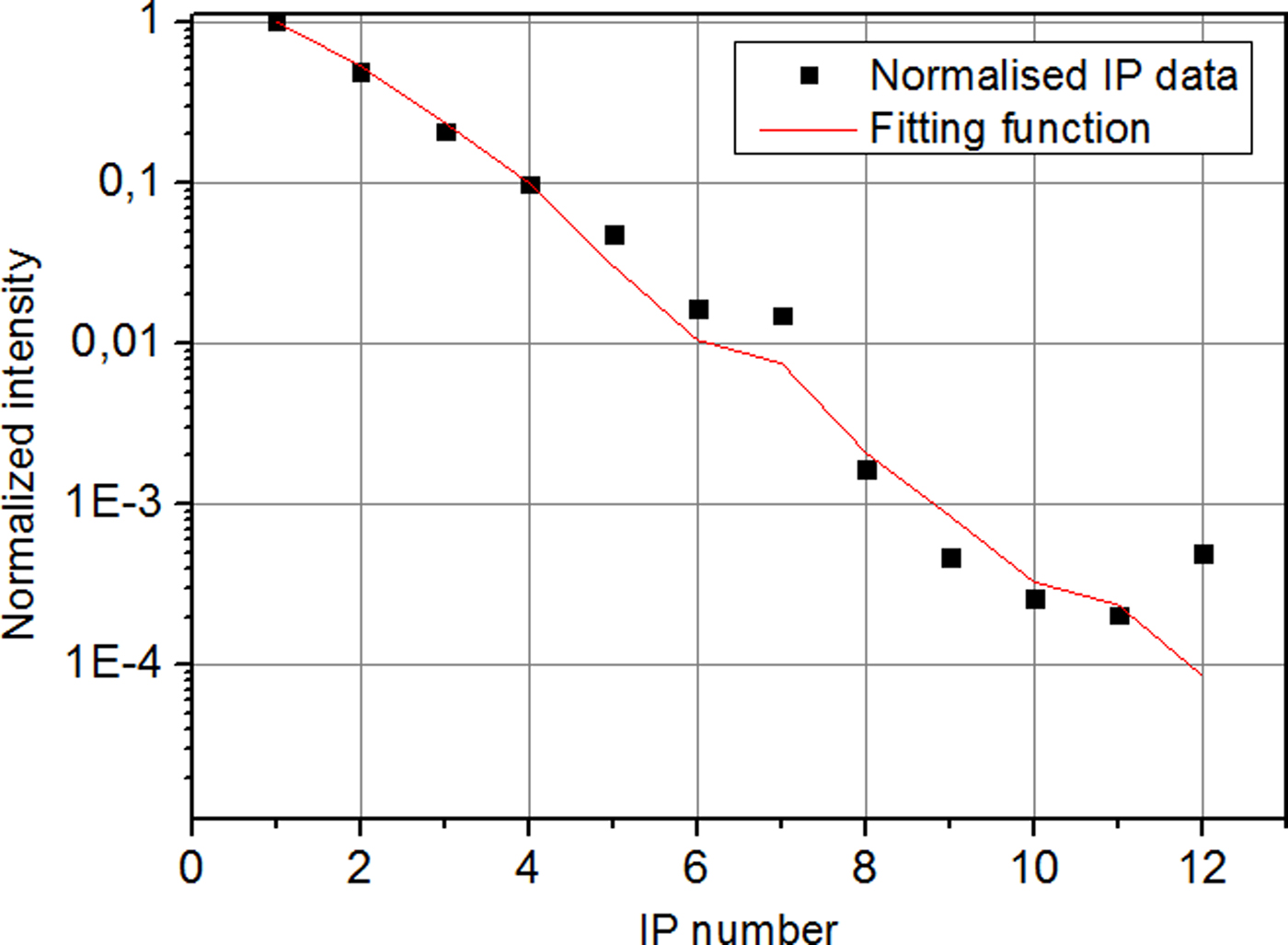
Fig. 12. IP intensity data (black points) and results obtained by using two-temperature distribution (red curve), as functions of the IP number.
In order to diagnose the transport of fast electrons, in addition to the Cu Kα imager, we also used an Highly Oriented Pyrolitic Graphite (HOPG) spectrometer (Legall et al., Reference Legall, Stiel, Nickles, Bjeoumikhov, Langhoff, Haschke and Wedell2005) to observe the X-ray Kα emissions from Ni- and Cu-plate. This detector allowed examining the penetration of fast electrons by comparing two Kα emissions generated at Ni plate and at Cu plate. Typical obtained spectra are shown in Figure 13.

Fig. 13. HOPG spectra versus energy of SP laser and delay between LP and SP lasers. Blue, Δt = 1 ns and SP energy E = 300 J; Red, spectrum with Δt = 1 ns and E ≈ 120 J; Green, spectrum with Δt = 2.7 ns and ≈ 120 J.
7. DISCUSSION
In the experiment we varied the energy of the LFEX laser beam and the delay between SP and LP. Figure 13 shows three spectra obtained during the experiment, two of them correspond to the same delay (i.e., similar implosion conditions) but different SP energy (300 J in blue, and 120 J in red). The measured Cu Kα line is clearly much stronger in the first case (larger SP energy). This result simply shows, as expected, that the fast electron number is increasing with the laser energy. The third spectrum (in green) is obtained with SP laser energy equal to 120 J but different delay. A delay of 1 ns when the target has just begun to implode (see the time diagram of implosion reported in Fig. 4), and the other with a delay of 2.7 ns, when target implosion has well advanced. At 1 ns the electron beam does not experience any pinch (Bell & Kingham, Reference Bell and Kingham2003), because the foam has not yet been compressed (Fig. 4). On the contrary, at 2.7 ns, there shall be a clear pinching as shown by Figures 6–8. Unfortunately, in all shots, except partially one with 300 J, the level of Ni Kα was compatible to noise and this does not allow drawing any definite conclusion on fast electron propagation due to the scarce knowledge of the fast electron source.
We also notice that all the spectra are characterized by strong Heα emissions from both the Ni and the Cu foil. Such strong Heα emissions show that the metal foils were heated to very high temperatures which may only result from direct laser heating (which may originate from the poor contrast of the LFEX beam at the time of the experiment) or by heating due to X-ray emission from the gold shield (as shown in the pinhole camera pictures of Fig. 10) following irradiation with the LP beam. Preheating, on the Ni foil can indeed have affected the conditions of fast electron generation from shot to shot. Also we performed some shots with the Gekko LP laser only and, even in this case, rather strong Cu Kα and Ni Kα lines were observed (see Fig. 14). Indeed the level of such emission was almost the same observed with the SP laser fired at low energy (≈ 120 J). Such very high “noise” level does indeed jeopardize the interpretation of results obtained in these conditions. At larger SP laser energy (≈ 300 J blue line in Fig. 13), the Cu Kα and Ni Kα lines were stronger and Kα emission induced by the LP laser had a small impact on data analysis.

Fig. 14. HOPG spectra obtained with and without the SP laser.
8. SUMMARY AND CONCLUSION
We studied electron transport through compressed matter, obtained by laser compression of target.
The study of electron transport, as a function of injection time, in such extreme states of matter, has been performed with advanced numerical plasma simulations (“reduced” kinetic models), which led to the prediction that electrons collimate before shock bounce and diverge after it.
In the experiment, X-ray Kα emissions induced by REB penetration were clearly seen. However, problems related to target preheating and strong X-ray noise prevented a quantitative analysis of obtained data. Such issues of target preheating and X-ray noise seem to originate from problems in target fabrication, from the poor intensity contrast of the SP beam at the time of the experiment, and from the low SP laser energy which was used in most shots. As recalled before, at the time of the experiment the main pulse impinged after a 2 ns foot pulse at 1012–1013 W/cm2. Now the contrast ration on LFEX has been improved (Ohira et al., Reference Ohira, Fujioka, Sunahara, Johzaki, Nagatomo, Matsuo and Azechi2012) and this foot has been suppressed with a pulse cleaner below 109–1010 W/cm2.
Finally, the low plasma temperature at the stagnation time did not allow to follow the full implosion of the target with the X-ray streak camera because of low X-ray emission. Maybe, this can be solved using lower density foams (thereby getting higher temperatures at stagnation). Perhaps doped with tracers giving higher X-ray emission in the final phase of implosion.
Cu Kα images, showed the passage of fast electrons propagating through the Cu foil placed on the end of the cylinder. Hence, even if quantitative analysis could not be performed, we have nevertheless provided the proof of principle of the feasibility of such an experiment and the test for the diagnostics to be used in a follow-up to the present study.
ACKNOWLEDGEMENTS
The authors want to thank the ILE technical team for the help, the ANR-TERRE for the fundings, Luca Antonelli, Luca Fedeli and Claudio Bellei for interesting discussions about this topic. They also acknowledge the support of the COST action MP1208 “Developing the Physics and the Scientific Community for Inertial Fusion”.


