


I. INTRODUCTION
Optical two-tone can be used for the microwave or millimeter-wave generation by receiving it with a photo detector (PD). This technique is suitably applied for transmitting and distributing RF clock signals at distant places through optical fibers [Reference Kawanishi, Sakamoto and Izutsu1, Reference Nagatsuma2]. A primary method of the two-tone generation is to use two laser sources [Reference Nagatsuma2]. The frequency of the RF signal is simply determined by the optical wavelength difference in two lasers, as long as the response speed of PDs is satisfied. However, the stability of generated RF signals in frequency and phase is generally not good. Optical single sideband (SSB) modulation is suitably applied for high-speed optical fiber communication, radio-on-fiber systems, and so on. Compared with the conventional intensity modulation, optical SSB signals occupy a narrow range of light wavelength and overcome the fiber dispersion [Reference Kuri, Kitayama, Stohr and Ogawa3].
Electro-optic (EO) modulators with the Mach–Zehnder (MZ) interferometer are commonly used for high-speed optical intensity modulations. The light modulation is performed by interference with two phase-modulated light waves. Linear intensity modulation is approximately realized at π/2 optical phase difference bias under the small signal operation. If we operate such modulators at π phase difference bias, optical two-tone is theoretically obtained and the frequency difference of the optical spectrum components is perfectly locked in double the modulation signal frequency [Reference Kawanishi, Sakamoto and Izutsu1]. Very true RF signal waves of doubled frequency can be obtained by receiving the optical two-tone with a PD. This scheme may be suitably applied to RF signal transmission through optical fibers, such as radio-on-fiber systems. On the other hand, the optical SSB modulation is also realized with the dual-electrode-type EO modulator by applying two RF signals with π/2 phase difference to each electrode under the condition of π/2 phase difference bias.
However, in the optical two-tone generation and the optical SSB modulation by the EO modulators, imbalances in the light interference, such as imbalance of the light split ratio, causes redundant or unexpected optical spectrum components, which may induce undesired harmonics in obtained RF signals and may disturb other optical signals occupying the neighboring light wavelength region in the same optical fiber. Direct compensation of the imbalance of the light split ratio has been realized by the MZ modulator with the active trimmers, where a sub-MZ intensity modulator is inserted in each arm of the main-MZ interferometer to balance the light intensities in the two arms [Reference Kawanishi, Tada, Murata and Enokihara4, Reference Kikuchi5]. As this modulator is highly functional, complicated control of the operation conditions of the MZ modulator sections is required.
Here we introduce a new and simple method to generate doubled frequency optical two-tone and optical SSB signals by suppressing the redundant spectrum components, where a single MZ interferometer-type EO modulator with the dual-electrode structure is used. The imbalance of the light splitting ratio which may be caused by fabrication errors is compensated by adjusting the input RF power applied to each electrode. This effect was experimentally confirmed. We also considered the spectra of RF signal generated at a PD from the optical two-tone propagated through a dispersive optical fiber and suppression of undesired RF spectrum components by this method.
II. DOUBLED FREQUENCY OPTICAL TWO-TONE GENERATION
A) Spectra of modulated light by MZ modulators
MZ modulators are generally used for light intensity modulation by the interference between two phase-modulated light waves. Figure 1 shows a schematic of the MZ modulator. When A 1 and A 2 represent amplitudes of the optical phase modulation in the two arms of the MZ interferometer, the optical phase shifts induced through propagation within the two arms, Δϕ 1 and Δϕ 2, are expressed by
where ω m is angular frequency of RF modulation signal. ϕ B1 and ϕ B2 are optical phase shifts in the two arms that are determined by the optical path length of each arm. ϕ m1 and ϕ m2 are the initial phase of the RF modulation signals for each arm. And the electric field of light output from the interferometer is

where E in and E out are electric field amplitudes of the input and the output light, respectively. ω 0 is angular frequency of light. b is an imbalance factor of the light split ratio between two arms. The attenuations of light waves are ignored in the discussions.

Fig. 1. Schematic of an EO modulator with an MZ interferometer and dual electrodes.
A 1 and A 2 normally have opposite signs with each other. Assuming A 1 > 0 and A 2 < 0, the light modulation index, which means an amplitude of the sinusoidal change of optical phase difference between two arms, is given by A = A 1 − A 2. For general MZ intensity modulators, since the push − pull operation is supported by a single RF signal, the balanced conditions, b = 0 and A 1 = −A 2, are desirable. Meanwhile, we purposely induce the imbalance of the phase modulation to suppress the redundant optical spectrum components. An imbalance factor in the phase modulation between the two arms is expressed as
The α corresponds to the chirp parameter at the small signal operation for MZ intensity modulators [Reference Koyama and Iga6]. The frequency spectrum of the modulated light is given by expansion of (2) with Bessel functions as

where J n is a Bessel function of the first kind. Relative intensity of the nth-order sideband component is expressed by using α, b, A, and ϕ B as

where I in is the input light intensity and n = 0 corresponds to the carrier component. We represent the optical phase difference bias of the MZ interferometer as ϕ B = ϕ B2 − ϕ B1. The phase difference induced between the two RF modulation signals, ϕ m = ϕ m2 − ϕ m1, is defined as the skew.
B) Two-tone generation condition
We consider the case of the modulator operation at ϕ B = π and ϕ m = 0, which is the minimum transmission point as shown in Fig. 2. The second harmonic modulation is realized in this point. Modulated light spectra in the conditions both of b = 0 and 0.1 are calculated as Fig. 3, where A = 0.5π and α = 0. It is seen that the optical two-tone of 2ω m spacing is obtained and that the even-order components R 0 and R ±2, also appear at the imbalance condition b = 0.1. These components R 0 and R ±2, which are redundant for two-tone waves, increase with |b| as shown in Fig. 4 where R 0, R ±1, and R ±2 are calculated as functions of b at A = 0.5π and α = 0.

Fig. 2. Output light responses of MZ modulator at ϕ B=π and ϕ m=0.

Fig. 3. Modulated light spectra at A=0.5π rad and α=0.

Fig. 4. R 0, R ±1, and R ±2 as functions of b at α = 0.
The extinction ratio, R ext, of the intensity modulation in low frequencies directly depends on the b as ![]() . The guaranteed range of R ext for MZ modulators available as a commercial product is typically more than 20 dB, which corresponds to |b| less than 0.1. The imbalance in the light splitting of b = 0.1 is therefore a possible case for common MZ modulators. Moreover, b is not adjustable since this imbalance is mainly caused by the fabrication errors of the optical waveguides. Meanwhile, by using the dual-electrode-type MZ modulator, where two separated modulation electrodes for the optical phase modulation are provided on each arm. α can be adjusted by the input RF power difference between the two electrodes as seen from (3).
. The guaranteed range of R ext for MZ modulators available as a commercial product is typically more than 20 dB, which corresponds to |b| less than 0.1. The imbalance in the light splitting of b = 0.1 is therefore a possible case for common MZ modulators. Moreover, b is not adjustable since this imbalance is mainly caused by the fabrication errors of the optical waveguides. Meanwhile, by using the dual-electrode-type MZ modulator, where two separated modulation electrodes for the optical phase modulation are provided on each arm. α can be adjusted by the input RF power difference between the two electrodes as seen from (3).
C) Suppression of redundant spectrum components
Figure 5 shows R 0, R ±1, and R ±2 as functions of α at A = 0.5π and b = 0.1. It is seen that the relative intensities of the carrier R 0, and the second-order sideband R ±2, remarkably change with α and disappear at around α = −0.3 and 0.05, respectively. From all other calculations, we found that the redundant spectrum components can be suppressed by introducing adequate amount of α. Here we defined the suppression ratios of the redundant components, R 0 and R ±2, to the first sideband ones, R ±1, as SR 0 = R ±1/R 0 and SR 2 = R ±1/R ±2, respectively. Figure 6 shows the regions A and B where SR 2 and SR 0 become more than 20 dB, respectively, in the α − A plane. It is seen that both redundant components are simultaneously suppressed by adjusting α and A in the overlapped area in Fig. 6.

Fig. 5. R 0, R ±1, and R ±2 as functions of α at b=0.1.

Fig. 6. Regions A and B where SR 2 and SR 0 are more than 20 dB, respectively, are indicated in α–A plane.
D) Experiments
The dual-electrode-type LiNbO3 MZ modulator was used for the experiments to confirm the effect of the redundant component suppression. Frequency of the RF modulation signal was 10 GHz and light wavelength is around 1.55 µm. The RF signal wave was divided into two by a power divider and these waves were individually adjusted to their intensity and phase by attenuators and delay controllers. And then the two waves were individually fed to each electrode of the modulator. The α is changed with difference in the phase modulation depth between the two arms of the MZ interferometer as seen from (3). Here, we adjusted the α by individually varying the RF signal intensities of those two waves. Optical phase difference bias ϕ B was controlled by DC voltage applied to additional electrodes provided besides the modulation electrodes. The output-modulated light was observed by an optical spectrum analyzer.
The extinction ratio, R ext, was measured in advance by detecting the output light intensity varied with the DC voltage for the ϕ B adjustment as 51.9 dB. Consequently, the imbalance factor of light splitting, b, of the modulator is estimated to 0.0026.
Figure 7 shows output optical spectra observed at various modulation indices drawn in the same graph. Figure 8 shows the spectrum at A = 0.56π rad with the horizontal axis corresponding to light wavelength. Since the carrier hid behind the noise level, the suppression ratio, SR 0, was expected to be higher than 49.8 dB. In the observations, α was fixed to maximize both SR 0 and SR 2, or to minimize both I 0 and I 2, by individually controlling the input RF powers fed to the two electrodes. However, we could not determine the exact value of α in these experiments because the amplitudes of the phase modulation, A 1 and A 2, in the two arms cannot be directly measured. The corresponding value for α can be calculated by using (5).

Fig. 7. Observed optical spectra of two-tone waves.

Fig. 8. Optical spectrum of two-tone generated by an MZ modulator at A = 0.56π rad.
If the modulator operates with α = 0, the SR 0 should be 45.4 dB by the estimation using (5) with b = 0.0026 and A = 0.56π rad. It is expected that the suppression ratio SR 0, improved by more than 4 dB by means of adjusting α. The corresponding value of α in the case of Fig. 8 is estimated to be 0.0045 using (5). Since the b of the modulator used in the experiment was considerably small, or close to the balanced condition, the intensities of the redundant components, I 0 and I 2, are expected to be small even at α = 0. When this method is applied for modulators with larger b, remarkable improvement of the redundant component suppression ratios will be obtained. It is revealed from these results that the high-quality optical two-tone was generated by this method.
III. OPTICAL SSB MODULATION
A) SSB modulation and suppression of the redundant sideband
Optical SSB signals can also be generated by an EO modulator with an MZ interferometer. One side of a pair of the first sidebands in the spectrum of the modulated light can be canceled out by setting the operation parameters as ϕ B = ±π/2 and ϕ m = ±π/2 in (5) so that the optical spectrum of SSB shape is obtained as shown in Fig. 9(a). Here we consider both of the first sidebands and the carrier only. This operation is an optical version of the phase shift method, which is usually realized by electric circuits.
However, the imbalance of the light split at the interferometer disturbs this sideband cancelation scheme so that the sideband to be eliminated should remain in the output light spectrum as shown in Fig. 9(b). This spectrum was calculated with the light split imbalance factor b of 0.1 and total modulation depth A of 0.5π rad. We consider suppressing such redundant sideband components by using the phase modulation imbalance factor α with the same way as the case of the two-tone generation. Figure 10 shows R 0 and R ±1 as functions of α at A = 0.5π and b = 0.1, where ϕ B and ϕ m are set as π/2 to eliminate R +1. Intensity of the first sideband at the higher frequency side, R +1, remarkably changes with α and completely eliminated at around α = 0.12. It was found from these calculations that the redundant sideband caused by the light split imbalance can be always canceled out by adequately adjusting the α.

Fig. 9. Light spectra of SSB modulation at A = 0.5π rad and α = 0.

Fig. 10. R 0, R +1, and R−1 as functions of α at A = 0.5π rad and b = 0.1.
B) Experiments
The same experimental setup as that in the two-tone generation was used for the experiment of the SSB modulation. The phase modulation imbalance factor α was adjusted to minimize I −1, which is intensity of a sideband at the upper wavelength side. Figure 11 shows the intensities of the carrier, I 0, and both of the first-order sidebands, I ±1, as functions of the total modulation depth A. Since the sideband, I −1, was hid behind the noise level in the measurements, the values of I −1 cannot be estimated from the figure.
Fig. 11. Measured intensities of carrier, I 0, and first-order sidebands, I ±1, as functions of the total modulation index A.
Figure 12 shows an example of the spectrum at A = 0.6π rad with the horizontal axis corresponding to light wavelength. Since the upper sideband was lower than the noise level, the suppression ratio of the redundant sideband to the carrier SR −1 = R 0/R −1, was expected to be higher than 50 dB, as shown in Fig. 12. The I −1 should be completely suppressed at α = 0.0034 according to the calculation using (5) with actual values of A and b. The corresponding value of α in the case of Fig. 12 is also expected to be around 0.0034. It is seen that the very high suppression ratio was realized by the SSB modulation with an EO modulator.

Fig. 12. An example of the spectrum of optical SSB signal modulated at A = 0.6π rad.
IV. THEORETICAL CONSIDERATION OF TRANSMISSION OF THE TWO-TONE THROUGH AN OPTICAL FIBER
Here, we theoretically consider the responses of RF signals generated by the optical two tone that is created by the MZ modulator and transmitted through an optical fiber. It is assumed that the optical fiber is dispersive and the PD has the squared detection property as shown in Fig. 13. When the two-tone generated by the EO modulator with PD is detected, the PD output signal should mainly consist of the second harmonic component of 2ω m.
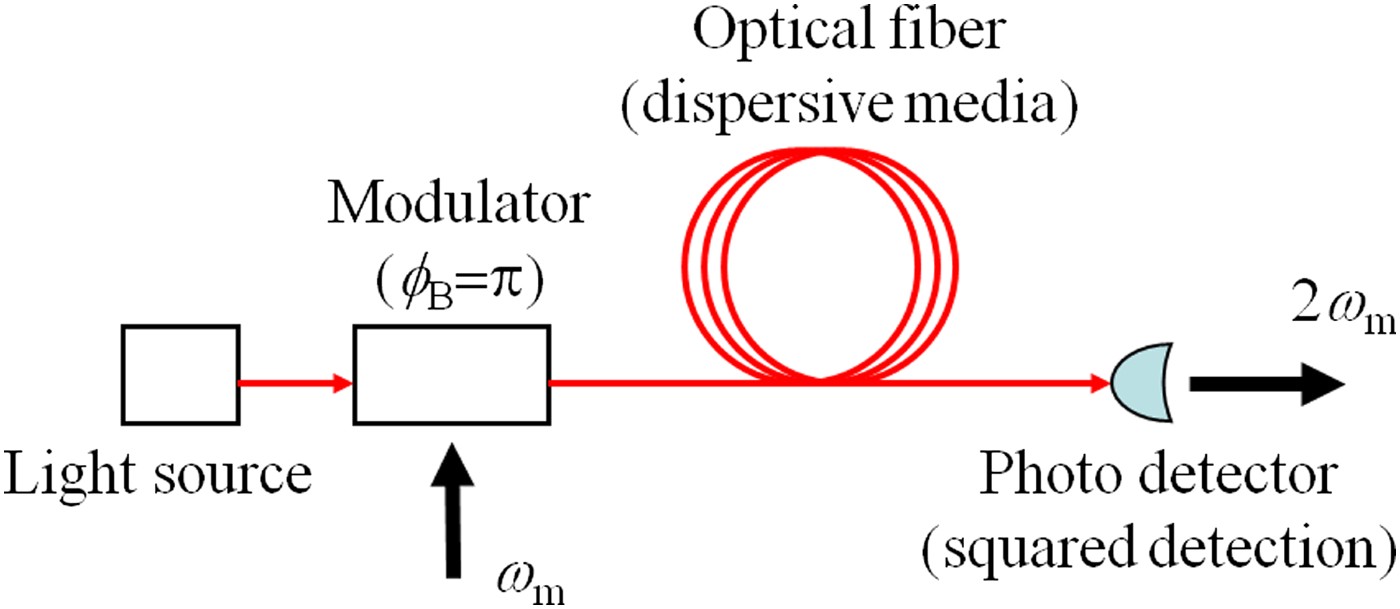
Fig. 13. Two-tone wave transmission through optical fiber and detection.
It is obvious that the fundamental component, ω m, is naturally suppressed at b = 0 and α = 0, or the balanced condition. When b is not zero, pairs of optical spectrum components of ω m spacing appear as shown in Fig. 3(b) so that the RF fundamental frequency component of angular frequency ω m as well as the second-harmonic ones might induce in the PD output signals.
Figure 14(a) shows the relative intensity of 2ω m and ω m components in the PD output at b = 0.1, α = 0, and A = 0.5π rad calculated as functions of the fiber length, L. Conditions in the calculations are as follows: the light wavelength is 1.55 µm, the dispersion parameter of the fiber is 16.7 ps/km/nm, the frequency of input RF is 10 GHz, and light attenuation is ignored. Optical sideband components higher than fifth order are not considered in the calculations.

Fig. 14. 2ω m and ω m components at b = 0.1 and A = 0.5π rad as functions of the fiber length, L, where intensity is normalized by that of 2ω m component at L = 0.
Even if b is not zero, the ω m component is canceled out by the squared detection process in the case of no dispersion or L = 0, on account of relations in phase between optical spectrum components, as shown in Fig. 14(a). This is an advantage of the two-tone generation by the MZ modulator. However, after propagating through the dispersive fiber, the ω m component is remarkably induced.
By calculating under the condition of α = 0.675, it is seen that this residual ω m component can be suppressed even at any fiber length as shown in Fig. 14(b). This is attributable to the feature that the adequate amount of α coordinates the intensity relation between the optical spectrum components so that the ω m component would be exactly canceled out through the process of the squared detection.
V. CONCLUSION
Doubled frequency optical two-tone and optical SSB signals were generated by the dual-electrode-type EO modulator using the proposed method for suppressing the redundant spectrum components.
It is revealed that MZ modulators with the proposed method would be suitably applied to the optical two-tone generation and the SSB modulation requiring high-quality optical spectra. These optical modulation techniques will be useful for the millimeter-wave generation or the optical fiber transmission of wireless signals, such as the radio-on-fiber systems.
ACKNOWLEDGEMENTS
The authors thank A. Tanaka and R. Satomura for their valuable contributions in this work.
 Akira Enokihara received B. Eng., M. Eng., and D. Eng. degrees in electrical engineering from Osaka University in 1982, 1984, and 1987, respectively. From 1987 to 2008, he worked in Matsushita Electric Industrial Co., Ltd., currently Panasonic Cooperation, Osaka Japan, where he has been engaged in research and development on microwave and millimeter-wave dielectric filters, microwave applications of high-Tc superconductors, and high-speed optical modulation devices. From 2008, he has been a professor of the Graduate School of Engineering, University of Hyogo, Hyogo, Japan. His current research interests include the areas of microwave and millimeter-wave engineering and microwave photonics.
 Tadashi Kawai was born in Hyogo, Japan. He received the B.S., M.S., and Ph.D. degrees from Himeji Institute of Technology (from April 1, 2004, University of Hyogo), Hyogo, Japan, in 1990, 1992, and 1995, respectively. He is currently an associate professor at Graduate School of Engineering, University of Hyogo. His research activity is mainly devoted to microwave and millimeter-wave passive components such as planar-circuit-type and waveguide-type directional couplers and multi-port hybrids. Dr Kawai is a member of the Institute of Electrical and Electronics Engineers.
 Tetsuya Kawanishi received the B.E., M.E., and Ph.D. degrees in electronics from Kyoto University, in 1992, 1994, and 1997, respectively. From 1994 to 1995, he worked for Production Engineering Laboratory of Matsushita Electric Industrial (Panasonic) Co., Ltd. In 1997, he was with Venture Business Laboratory of Kyoto University, where he had been engaged in research on electromagnetic scattering and on near-field optics. He joined the Communications Research Laboratory, Ministry of Posts and Telecommunications (from April 1, 2004, National Institute of Information and Communications Technology), Koganei, Tokyo, in 1998. He was a visiting scholar at the Department of Electrical & Computer Engineering, University of California at San Diego, USA, in 2004. He is now a research manager of the National Institute of Information and Communications Technology, and is currently working on high-speed optical modulators and on RF photonics. He received the URSI Young Scientists Award in 1999.


