


NOMENCLATURE
- x
-
chordwise distance
- y
-
normal (to the wing surface) distance
- z
-
spanwise distance
- U ∞
-
freestream velocity
- U
-
streamwise velocity
- V
-
vertical velocity
- W
-
spanwise velocity
- c
-
chord
- AR
-
aspect ratio
- ω x
-
streamwise vorticity
- τ P
-
characteristic time of a particle
- τ f
-
characteristic time of the flow
- ρ P
-
density value of the particle
- d p
-
diameter of the particle
- μ
-
viscosity of the air
- L
-
characteristics length of the body
- U ∞
-
freestream velocity
- σ u
-
uncertainty in velocity
- σ P
-
uncertainty in pixel displacement
- M
-
magnification factor
- Δ t
-
time between the laser pulse
- F1,F2
-
Foci
- S
-
saddle point
- B
-
bifurcation line
1.0 INTRODUCTION
The design and development of Micro Air Vehicles (MAVs) has recently gained considerable attention in the aerospace community due to its numerous military and civilian applications like surveillance, search and rescue, damage assessment and reconnaissance without direct risk to a human crew. MAV designs vary and can range from fixed-wing designs to rotorcraft, flapping wings, flexible structures and bio-inspired designs. Most fixed-wing MAVs have low-aspect-ratio (AR: 1.0-1.5) wings with span between 0.075 and 0.3 m and a forward velocity of about 10-15 m/s, resulting in flight Reynolds numbers of 5 × 10⁴ to 2 × 10⁵. At this flight Reynolds number range, the laminar separation bubble formed on the aerofoil causes a deterioration in performance with lower lift, higher drag and earlier stall characteristics(Reference Mueller and DeLaurier1). However, as the flow field around the low-aspect-ratio wing (MAV) is highly three dimensional due to the formation of vortical structures from the wing leading edge(Reference Pelletier and Mueller2,Reference Torres and Mueller3) , the spanwise extent of the laminar separation bubble is highly minimised. The leading edge vortex enhances the performance of MAV configuration in terms of higher lift (non-linear contribution) and increased stall angle compared to the basic aerofoil(Reference Shyy, Lian, Tang, Viieru and Liu4). Muller et al(Reference Mueller and Torres5) reported the influence of chordwise location of maximum span (as measured from the leading edge) in wing planform on the leading edge vortex formation and its distance between the leading edge vortices. Numerical and experimental studies(Reference Jian and Ke-Qin6) on a low-aspect-ratio wing revealed that the flow structure exhibits bilateral symmetry in vortical structures generated from the wing tip at an angle incidence of 10° and bilateral asymmetry at a 35° incidence. Recently, Particle Image Velocimetry (PIV) (2D and stereo) studies(Reference Khabatta, Ukeiley, Tinney, Standford and Ifju7) on a MAV wing reported the formation of counter-rotating vortical structures from the tip and a laminar separation bubble in the reflexed region of the wing at the mid-span. It should be noted that these studies did not include the influence of propeller-induced flow on the aerodynamic characteristics and the associated flow field. Mukund et al(Reference Mukund and Chandan Kumar8) investigated the effect of MAV wing configuration on the flow field and aerodynamic performance in the absence of propeller slipstream. The flow field at high angle of incidence (20°) showed the tip vortex as well as presence of a laminar separation bubble on the wing surface. There have been several studies(Reference Witkowski, Lee and Sullivan9-Reference Roosenboom, Heider and Schrder12) on the effect of propeller slipstream interaction with wing flow field on propeller efficiency, wing-induced drag and wing lift curve slope. However, these studies relate to high-aspect-ratio wings, unlike the low-aspect-ratio MAV wing sought to be addressed here. Additionally, as the propeller covers nearly 50% of the span of the MAV wing(Reference Null, Noseck and Shkarayev13,Reference Thipyopas and Moschetta14) , the interaction of the propeller slipstream with the wing flow field is expected to strongly influence the aerodynamic characteristics of the MAV. Efforts were made in the past(Reference Null, Noseck and Shkarayev13-Reference Catalano15) to study the effect of propeller-induced flow on the aerodynamic characteristics of a MAV with pusher and tractor configurations. The results from these studies have shown the enhancement of aerodynamic characteristics of the wing, increased lift and delayed stall during power-on condition. This performance improvement is function of location and orientation of propeller with respect to the fuselage. Recently, Ananda et al(Reference Ananda, Deters and Selig16) studied the influence of propeller slipstream in triggering an early transition to turbulent flow for a moderate aspect ratio (AR = 4) wing at low Reynolds numbers. Arivoli et al(Reference Arivoli, Dodamani, Antony, Suraj, Ramesh and Ahmed17) investigated the effect of propeller-induced flow on the aerodynamic characteristics of a fixed-wing low-aspect-ratio (AR = 1.46) MAV, through a decoupled motor and propeller arrangement for force measurements. These studies showed significant increase in lift and stall angle under propeller-on condition. Choi et al(Reference Choi, Ahn, Maresca and Benneceur18) and Deng et al(Reference Deng, Van Oudheusden, Xiao and Bijl19)attempted a computational prediction of the flow field for pusher and tractor MAV configurations. However, accurate prediction of the complex flow field of a low-aspect-ratio wing with propeller slipstream using computational methods is still challenging, especially at low Reynolds number for high angle of incidence. Gamble and Reeder(Reference Gamble and Reeder20) carried out force and velocity field measurements on rigid and flexible wing MAVs under propeller-on conditions at a distance of one propeller diameter. They found that the propeller slipstream increases the streamwise velocity by a factor of 1.16. However, a complete flow-field development on a MAV wing in the presence of a propeller slipstream is yet to be reported in the literature. Most of the numerical studies on the MAV models consider a (thin) wing alone(Reference Jian and Ke-Qin6) or a wing-motor configuration(Reference Choi, Ahn, Maresca and Benneceur18). However, in actual practice, virtually all MAVs employ a stub fuselage to mount the motor. This stub fuselage is a three-dimensional body and will have significant influence on the wing flow field, especially at large incidences.
The goal of the present work is to investigate the effect of propeller slipstream on the vortex flow field over a low-aspect-ratio modified inverse Zimmerman wing, qualitatively (oil flow) and quantitatively (Stereo Particle Image Velocimetry), at a low Reynolds number. While MAV wings vary widely, this particular wing has been extensively used for low-aspect-ratio MAVs and is therefore chosen here for the present study(Reference Austin21). Further, the earlier study of Arivoli et al(Reference Arivoli, Dodamani, Antony, Suraj, Ramesh and Ahmed17), has shown significant differences in lift coefficient between propeller-on and propeller-off condition beyond an angle of incidence of 20°. Oil flow visualisations were carried out at several angles of attack to understand the evolution of flow field on MAV wing surface, with and without the presence of propeller slipstream. Since severe asymmetry is observed at high incidence, the PIV measurements of the off-body velocity field in the absence and presence of propeller flow are carried out at a 24° angle-of-attack to capture the effect of the propeller on the flow field. While the typical angles of attack of MAVs during flight are about 8°-10°, sudden vertical gusts can cause large incidences. It is therefore of interest to understand the vehicle behaviour by documenting the three-component flow field at such conditions.
2.0 EXPERIMENTS
The measurements were carried out in the low-speed wind tunnel at the National Aerospace Laboratories (NAL), Bangalore. The test section has a cross-section of 1.5 m × 1.5 m and a length of 6.5 m with the model support system at the centre of the test section. The freestream velocity in this continuous, open circuit tunnel can be varied in the range of 10–55 m/s and freestream turbulence level is within 0.12% in the above speed range with mean velocity uniformity within 0.2%. The model is mounted in the wind tunnel using a sting linked to a pitching sector mechanism. The solid blockage (based on an equivalent projected area) at 24° angle of incidence was found to be 1.3%. The tests were conducted at a freestream velocity of 10 m/s, corresponding to a Reynolds number based on a root chord of about 1.6 × 10⁵.
2.1 Model configuration
Surface oil flow visualisation and stereo-PIV measurements were carried out on a typical fixed-wing MAV model (Fig. 1(a)). The wind-tunnel model mounted in the tunnel is shown in Fig. 1(b). The model has a high wing configuration with modified inverse Zimmerman wing planform. The cross-section of the wing is a Selig 4083 aerofoil camber with maximum camber of 3% located at 40% from the leading edge. The wing has a root chord of 250 mm and span of 300 mm with uniform thickness of 3 mm. The aspect ratio of the wing is 1.46. The wing is attached with fuselage of a rectangular configuration with a stub at the front and a boat tail at the rear. Simulation of the stub front end, which typically houses the motor of the propeller, is expected to have a significant effect on the flow symmetry at high incidence and was thus deemed necessary. The motor and propeller arrangement is mounted on the nose of fuselage for power-on measurement. The propeller is run at a constant rpm of 8500 for power-on measurements. This is very close to the test condition of the earlier study for the force measurement(Reference Arivoli, Dodamani, Antony, Suraj, Ramesh and Ahmed17). The motor used is an AXi 2203/46 (KV 1720) DC brushless motor and the propeller mounted on the motor is a GWS® 7′′ × 3.5′′ propeller. The motor was powered by an external DC power supply source located outside the tunnel. The propeller rpm is monitored using a tachometer (mounted on the sting) output connected to an oscilloscope. The tachometer sensed the propeller rpm by receiving reflected laser light from the propeller tip where a strip of light-reflecting tape was fixed. The propeller rpm was controlled by setting the required voltage. The variation in the propeller rpm due to voltage fluctuation and tunnel freestream velocity variation is ± 0.5%. The motor and propeller were removed from the fuselage nose for the measurements at power-off conditions. This was done as there was no facility to prevent the wind milling of the propeller during the propeller-off case. Additionally, a stationary propeller (even in the horizontal position), as well, would have influenced the flow field over the MAV.
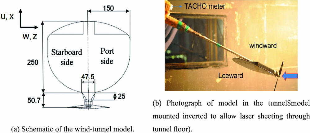
Figure 1. Wind-tunnel experimental set-up.
2.2 Oil flow visualisation
Surface flow visualisation is carried out using a mixture of titanium dioxide, oleic acid and SAE 60 grade vacuum pump oil in the ratio of 1:5:7. The mixture was sprayed on to the model by means of repeated flicking of the bristles of a paint brush until the model was covered with uniformly sized, discrete dots of a size (about 0.5 mm) that did not move under the influence of gravity. The tunnel flow was then brought rapidly to flow condition (within 3 seconds) and the streamlines then formed naturally on the model surface. The tunnel was run until the oil had stopped moving. The model was photographed in-situ after stopping the tunnel. The visualisations were carried at angles of incidence of 10°, 15°, 20° and 24° with propeller-on and propeller-off conditions. The uncertainty in angle of incidence of the pitching sector mechanism is ± 0.1°. The angles of incidence were selected from force measurement studies on the same wing(17).
2.3 Stereoscopic particle image velocimetry (SPIV)
Stereo PIV measurements were carried out at an incidence of 24° to capture the flow field over the MAV wing during propeller-off and propeller-on conditions. This specific angle is chosen by an analysis of the oil flow visualisation images where substantial difference in the vortex flow is seen in the surface oil flow pattern between propeller-off and propeller-on conditions at 24°. Measurements were carried out in the spanwise plane at four chordwise (Fig. 2) locations to capture the development of the flow field on the wing from the leading edge to the trailing edge.
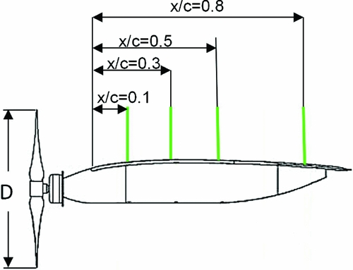
Figure 2. SPIV measurement planes.
The model was mounted in an inverted position on the sting during PIV the measurement as the optical access for the light sheet is available through the tunnel floor. Stereo-PIV images were acquired using a MotionPro® Y5 camera of 2314(H) × 1728(V) pixels with a Nikkor® 85 mm Schiempflug lens. The photograph and schematic of the experimental set-up for stereo-PIV measurement is shown in Figs 3(a) and 3(b). The cameras were mounted on either sides of the tunnel. The off-axis angles of the port and starboard side cameras, with respect to the object plane, were set at θ = 44.75° and 45.5°, respectively, in a manner that the axis passing through the centre of the image plane of both cameras intersected at the centre of the object plane. The Scheimpflug condition (rotation of the image plane with respect to the lens plane (α)) was applied using tilt shift mounts on the lens such that the entire area in the object plane was in good focus. The flow-field with tracer particles was illuminated by a double pulsed, frequency doubled dual cavity Nd:YAG, PIV 400 laser, which provides 400 mJ of energy per pulse at 532-nm wavelength. The optimum performance of the laser is at 15 Hz (15 pairs per second). The beam from the laser was spread as a thin sheet of light (thickness of 1 mm) with nearly flat intensity profile in the measurement plane. Since the model angle of incidence is 24°, it is required that the laser light sheet, as well as the camera, has to be mounted with a pitch angle of 24° with respect to the tunnel vertical axis (66° to the tunnel horizontal axis) so as to capture the tip vortex. The error in pitch angle setting of the light sheet as well as the camera was ± 0.1°. This arrangement provided a flat imaging area of 150 mm × 400 mm at the measurement planes on the model. The camera and the light sheet were moved together so as to use the same calibration at each measurement plane. The synchronisation of laser and the camera image acquisition was achieved through an IDT Motion-Pro® timing hub. The post processing of the acquired images were carried out with IDT ProVISION® XS software. Mean velocities were estimated by averaging an ensemble of 2,000 image pairs. The laser pulse separation time was fixed at 30 μs to allow the particles to move at least two pixels corresponding to the maximum velocity in the measurement region. The velocity vectors were obtained by processing the images with a 24 × 24 pixel interrogation window and 50% overlap. A spatial resolution of 4 mm in both directions (X and Y) was achieved. The flow field was seeded by injecting the fog having particle size 5 μm at the wind-tunnel entry. The fog was generated by using commercially available fog liquid (ethylene glycol) through the ANTARI® Z3000 fog machine. The fidelity of the seeding particles in following the flow over the model was ensured by evaluating stokes number (Stk) defined as:
 $$\begin{eqnarray*}
Stk = \frac{{\tau }_{p\ }}{{\tau }_f} \nonumber \\
{\tau }_p = \frac{{\rho }_{p\ \ }d^2_{p\ }}{18{\mu }} \nonumber \\
{\tau }_f = \frac{L}{U_{\infty }} \nonumber
\end{eqnarray*}$$
$$\begin{eqnarray*}
Stk = \frac{{\tau }_{p\ }}{{\tau }_f} \nonumber \\
{\tau }_p = \frac{{\rho }_{p\ \ }d^2_{p\ }}{18{\mu }} \nonumber \\
{\tau }_f = \frac{L}{U_{\infty }} \nonumber
\end{eqnarray*}$$

Figure 3. SPIV experimental set-up.
The characteristic time for a seeding particle is 0.0957 μs and that for the flow is 25 ms. The Stokes number based on particle and flow time scale is 3.828 × 10⁻⁶. Since the Stokes number is Stk ≪ 1, it ensures that the particles will follow the flow in the present flow condition(Reference Tropea, Yarin and Foss22). According to Willert et al(Reference Willert, Raffel, Kompenhans, Stasicki and Kahler23), an absolute best-case estimate for pixel displacement uncertainty (σ P ) is 0.01 pixels. The uncertainty of velocity is calculated using:
 $$\begin{eqnarray*}
{\sigma }_u = \frac{{\sigma }_pM}{\Delta t} \nonumber
\end{eqnarray*}$$
$$\begin{eqnarray*}
{\sigma }_u = \frac{{\sigma }_pM}{\Delta t} \nonumber
\end{eqnarray*}$$
Based on this pixel displacement uncertainty, the uncertainty in velocity measured for the present measurement (M = 0.18 mm/pixel, t = 30 μs) is 0.06 m/s. However, in practice, the uncertainty in pixel displacement is closer to 0.1 pixel(Reference Willert, Raffel, Kompenhans, Stasicki and Kahler23), which gives the velocity uncertainty value of 0.6 m/s. In order to carry out phase averaged stereo PIV measurement behind a propeller blade when its position is perpendicular to the root chord and leading edge of the wing, the passage of the propeller blade and the laser triggering needs to be synchronised. Since the propeller running frequency (140 Hz at 8,500 rpm) is much higher than the optimal laser-triggering frequency (15 Hz), a circuit was made to get a 14 Hz trigger output signal for the laser which is synchronised with desired propeller position with respect to wing root chord and leading edge. The block diagram of the triggering circuit is shown in Fig. 4. A tachometer was mounted on the sting of the pitching sector mechanism to obtain the frequency of revolution of the propeller. The output of the tachometer was fed to an electronic circuit to generate the digital pulses with 1.6% of duty cycle. A synchronisation pulse was input to a monoshot to generate a pulse of 10% of duty cycle. These pulses underwent an AND operation to generate the 15 Hz trigger output signal of 12% duty cycle. This output signal was fed to the IDT® timer box to trigger the laser. The angular displacement of the propeller blade position between the pulses of 30 μs in each pair is 1°. The uncertainty in the propeller position due to phase jitter during the synchronisation is estimated from movement of the reflection from the reflective tape on the propeller blade seen in the acquired images. The variation in the propeller position due to phase jitter is 7 pixels, which is equivalent to a linear displacement of 1.2 mm.

Figure 4. Block diagram of triggering circuit for laser.
3.0 RESULTS AND DISCUSSION
3.1 Oil flow visualisation
Images from the oil flow visualisation carried out at angles of incidence of 10°, 15°, 20° and 24° for propeller-off and propeller-on conditions are presented in Figs 5–8. The primary attachment line, secondary separation line, primary vortex and secondary separation region on the leeward side for both propeller-off and propeller-on conditions are clearly discernable from the images shown in Figs 5(a) and 5(b). The primary attachment line moves inboard with an increase in the angle of incidence. Mukund et al(Reference Mukund and Chandan Kumar8) described the surface flow patterns for several MAV wing configurations, in which the vortex was formed behind the leading edge of the wing. In the present study, the vortex formed on the entire leading edge is bifurcated at the corner of the wing fuselage junction. The location of the primary and secondary attachment lines is probably influenced by the location and size of the stub fuselage, which also is the cause of a body vortex. In the absence of the fuselage, the tip vortex would be expected to occur at a location further downstream in chord and more outboard in span. At angles of incidence 10°(Figs 5(a) and 5(b)) and 15° (Figs 6(a) and 6(b)), the flow pattern does not show a substantial difference between propeller-off and propeller-on conditions as for the location of primary attachment and secondary separation and the extent of the primary vortex region. A small movement of the secondary separation location towards the leading edge in the inboard region (near fuselage) is observed at 15° angle of incidence. At angles of incidence of 20° (Fig. 7(a)) and 24°(Fig. 8(a)), the primary attachment and secondary separation lines have moved inboard and the vortex has grown in size compared to that at angles of incidence 10° and 15° for the propeller-off condition. A small asymmetry appears at 20° (Fig. 7(a)), which becomes significantly pronounced at 24° (Fig. 8(a)). The propeller flow reduces this asymmetry significantly (Figs 7(b), 8(b)), as well as moves the secondary separation line towards the leading edge. The spanwise distance between the leading edge vortices is slightly increased for the propeller-on condition as compared to the propeller-off case. As reported earlier(Reference Mueller and Torres5), the wing performs better if the spanwise distance between the leading edge vortices is larger. The wing in the propeller slipstream would therefore exhibit better performances because the propeller slipstream increases the spanwise distance between leading edge vortices. Mukund et al(Reference Mukund and Chandan Kumar8) reported that the flow separated symmetrically from the wing surface at the higher angle-of-attack (20° and 25°). It should be noted here that the presence of the stub fuselage probably exacerbates the asymmetry induced at high angles similar to the behaviour seen and extensively studied on conical bodies at high incidences(Reference Ericsson24,Reference Viswanath25) . However, in a realistic situation, a stub fuselage for housing the propulsive system is necessary. The data show that careful design of the stub fuselage is necessary for MAV.

Figure 5. Surface oil flow pattern at α = 10°.

Figure 6. Surface oil flow pattern at α=15°.

Figure 7. Surface oil flow pattern at α=20°.

Figure 8. Surface oil flow pattern at α=24°.
3.2 Stereo PIV measurement
The three component velocity field at four spanwise planes along the chord (x/c = 0.1, 0.3, 0.5, 0.8) was documented using stereo PIV for propeller-off and propeller-on conditions at 24° incidence. This incidence was chosen based on the oil flow visualisation which showed that the pronounced asymmetry present during propeller-off was alleviated and symmetry restored at the propeller-on condition. It is therefore of interest to document the off-body flow topology using stereo PIV at this incidence.
In the contour plots (Figs 9–13), y/b and z/b represent distance normal to the wing surface and transverse distance along the span of the wing, respectively. The parameter for non-dimensionalising was chosen as the local span at the measurement plane station. The value of z/b = 0.5 indicates the location of the edge of the wing. The negative and positive z/b values in contour plots represent port and starboard side of the wing, respectively. The plots of the cross-flow (in plane) velocity vector field superimposed on the non-dimensionalised (with freestream velocity) mean streamwise velocity contours at all measurement planes are shown for propeller-off (Fig. 9(a)) and propeller-on (Fig. 9(b)) conditions, respectively. The magnitude of the cross-flow velocity vector in the plane perpendicular to the streamwise velocity depends on the relative magnitudes of vertical and spanwise velocity. When the propeller is off (Fig. 9(a)), the streamwise velocity has a small negative magnitude region close to the surface of the MAV wing. The extent of this low-velocity region increases from leading edge to trailing edge. However, the magnitude of negative streamwise velocity in the low-velocity region near the wing surface decreases as the region grows (towards the trailing edge). This behaviour is similar to that exhibited by low-sweep delta wings. In general, wake-type streamwise velocity profiles are seen in the primary vortices, prior to vortex break down on low-sweep non-slender delta wings at high angle of incidence and low Reynolds number, as seen in earlier studies(Reference Ol26). The post-vortex breakdown on the non-slender delta wing is usually identified through the wake-like streamwise velocity profile with negative or zero magnitude within the vortex core(Reference Ol and Gharib27,Reference Gordnier and Visbal28) . However, this nature of flow is confined within the vortex core. In the present study, negative velocity regions in the plots of mean streamwise velocity give the impression of breakdown of the vortex structures for the propeller-off condition at measurement planes x/c = 0.1,0.3 and 0.5. However, the cross-flow velocity vector superimposed on the streamwise velocity field in the measurement plane at x/c = 0.8 indicates the presence of swirling flow (weak vortex) above the wing. The diameter of the swirl looks expanded due to the moderate value of magnitude of the vertical and tangential velocity component as well as the small magnitude of streamwise velocity (wake) in the core(Reference Delery29,Reference Anthony, Pascal and Didier30) .

Figure 9. Mean streamwise velocity contour at α=24°.

Figure 10. Mean vertical velocity contour at α=24°.

Figure 11. Mean tangential velocity contour at α=24°.

Figure 12. Stream traces of velocity field at α=24°.

Figure 13. streamwise vorticity contours at α=24°.
In the propeller-on case (Fig. 9(b)), the propeller slipstream increased the magnitude of streamwise velocity behind the propeller at all measurement planes. An increase of nearly 50% in streamwise velocity was observed at x/c = 0.1. A small region of velocity drop is seen in the velocity contour at the centre of this measurement plane. This is probably the wake of the propeller blade near the root portion. The influence of propeller slipstream on increase of streamwise velocity reduces towards the trailing edge. However, the magnitude of streamwise velocity above the low-velocity region remains higher than for the propeller-off condition. The propeller slipstream energises the flow on the wing, which resulted in the significant reduction in the extent as well as the magnitude of negative streamwise velocity (reversed flow) near the wing surface compared to the propeller-off condition. The size of low-velocity region is smaller on the starboard side compared to the port side.
The increase in magnitude of cross-flow velocity (vertical and spanwise) by the propeller slipstream can be seen in the increase in vector length at all measurement planes. The reduction in the diameter of the swirling flow seen in the cross-flow velocity vector plot indicates stronger vortex formation on the wing at measurement planes corresponding to x/c of 0.5 and 0.8. The positive magnitude of streamwise velocity inside the vortex shows suppression of vortex breakdown and presence of vortex, even in the port side of the wing, similarly as seen in the oil flow pattern.
Figs 10(a) and 10(b) show the contours of a non-dimensionalised vertical velocity component along with the vector field of in-plane velocities at four measurement planes (x/c = 0.1, 0.3, 0.5, 0.8) for propeller-off and propeller-on condition. The oil flow images (Fig. 8(a)) show better defined oil flow streaks on the starboard side compared to the port side. From the oil flow patterns, we can infer the presence of a weak and expanded vortex on the port side and a strong and compact vortex on the starboard side, respectively. The asymmetry in the oil flow pattern is also observed in the vertical velocity contours (Fig. 10(a)) at all measurement planes. Higher magnitudes of positive vertical velocity can be seen in the velocity field near the tip region due to flow induced by the pressure difference between the lower and upper surface of the wing. A shear layer emanates as the flow separates from the wing tip. This separated shear layer rolls into the vortex core. The flow induced by this vortex attaches on the wing surface and after reattachment, the flow is chordwise in the inboard region of the wing and in the spanwise direction at the outboard region which forms the secondary separation. The negative vertical velocity indicates the reattachment of flow induced by the separated shear layer from the wing tip (as seen from the contour plot), corresponding to the primary attachment. The magnitude and extent of the region of positive vertical velocity in the tip region on the port side is higher than the starboard side for the propeller-off case, indicating the flow asymmetry. The extent of the negative vertical velocity region increases in the downstream direction from leading edge to trailing edge. This is consistent with the swirling flow seen in the in-plane velocity vector field at x/c = 0.8 as well as the oil flow images in Fig. 8(a).
For the propeller-on case (Fig. 10(b)), symmetry is somewhat restored at locations of x/c greater than 0.1. At x/c = 0.1, there still seems to be significant asymmetry due to the direction of the propeller being the same as the already asymmetrical vertical velocity field. Downstream, the symmetry is restored. Except at x/c = 0.5, an increase in the magnitude of vertical velocity above the port-side wing tip is seen at measurement planes x/c = 0.1,0.3 and 0.8. This could be due to the fact that the rotation of the propeller in the same direction gives additional increase in the vertical velocity apart from the upward flow induced by the pressure at the wing tip. The magnitude and extent of the negative vertical velocity region is higher in the propeller-on condition. The value of the negative vertical velocity increases in the downstream direction from the leading edge. The value and extent of the region of negative vertical velocity is higher in the measurement planes corresponding to x/c = 0.5 and 0.8 as compared to x/c = 0.1 and 0.3.
Non-dimensionalised tangential velocity contours for the propeller-off condition show (Fig. 11(a)) substantial asymmetry at the initial streamwise position of x/c = 0.1. At downstream locations, this asymmetry is mitigated, resulting in near symmetrical flow at x/c = 0.8. The magnitude of tangential velocity (spanwise flow) near the surface is lower in the port side as compared to the starboard side. This could have been the reason that the minimal oil flow movement is seen on the port side for the propeller-off case. In the propeller-on case (Fig. 11(b)), due to the slip stream, the magnitude of tangential velocity increases on moving from leading edge to trailing edge when compared to the propeller-off case. The magnitude of tangential velocity (both positive and negative) is almost equal (symmetry) on the both sides of the wing.
Stream traces using cross-flow velocity components (V, W) at the four measurement planes for the propeller-off and on condition are presented in Figs 12(a) and 12(b). Stream traces represent the locus of resultant velocity vector of vertical (V) and tangential velocity (W) components at each point in the measurement plane. The stream traces at x/c = 0.1 exhibit significant asymmetry between port and starboard. The stream traces on the port side shows bifurcation line (B-attachment type) on the port side and focus (F2-attachment type) on the starboard side(Reference Goruney and Rockwell31,Reference Tobak and Peake32) . The saddle point (S-attachment type) away from the wing shows the flow comes on to the wing surface and attaches asymmetrically. The vortex from both port and starboard side moves away from the wing root as well as from the wing surface in downstream locations (trailing edge). At x/c = 0.3, stream traces show foci (F1,F2-separation type) on both sides of the wing. However, the size of the foci and the location of saddle point (S) is not symmetric with respect to the wing root (z/b = 0). The saddle point (S-attachment type) position is symmetrically located in the flow field for the measurement plane at x/c = 0.5. However, the stream traces around the focus (F1-attachment type) on the port side are different than that seen on the starboard side (F2-separation type). Further, at x/c = 0.5, the focus (F1) on the starboard side is lifted off from the wing surface. At x/c = 0.8, the closed circles (focus centre) within the foci (F1,F2-separation type) show presence of clear and well-developed swirling flow on both port and starboard side. The stream traces move upwards at the port side just below the focus (F1) and near the wing-tip region. This could have been due to the higher magnitude of positive vertical velocity near the tip and lower magnitude of tangential velocity near the wing surface. On the starboard side, the stream traces near the wing surface below the focus (F2-separation type) move towards the wing tip. The magnitude of vertical velocity near the tip and tangential velocity above the wing surface is higher on starboard side as compared to the post side. This could be the reason for the difference in the diameter of the swirl flow seen in the stream traces between port and starboard side. Even though the streamwise contours exhibit symmetry, the asymmetry seen in the swirl flow is due to the difference in the magnitude of vertical and tangential velocity between port and starboard side. Taylor et al(Reference Taylor, Schnorbus and Gursul33), who studied the vortex flow over a low-sweep delta wing at angle-of-attack of 20°, show the absence of a swirl flow pattern in the apex region of the wing and re-establishment of swirl flow towards the trailing edge, suggesting that the breakdown of the vortex in the apex region is followed by a restoration of the vortex in the downstream region. A similar kind of flow pattern is observed from the stream traces in the port side for the propeller-off condition.
In the propeller-on case, the stream traces clearly show the swirling flow pattern on both port and starboard side of the wing. The stream traces show slight asymmetry (stream traces moving up in the port side) at x/c = 0.1 and 0.3 near the tip due to the higher vertical velocity magnitude due to the direction of propeller rotation. Further, the location of saddle point (S-attachment type) and shape of the foci (F1,F2-separation type) also show mild asymmetry in the stream traces at x/c = 0.1 and 0.3. However, the stream traces look symmetrical in the measurement planes at x/c = 0.5 and 0.8. The centre of the focus (F1,F2-separation type) seen in the stream traces were very close to the surface of the wing, except at x/c = 0.8. The centre of the focus moves towards the outboard of the wing as we move from leading edge to trailing edge. The stream traces due to the propeller slipstream display greater symmetry as compared to the propeller-off condition.
Contours of streamwise (out-of-plane) vorticity ω x , are shown in Figs 13(a) and 13(b) for the propeller-off and propeller-on conditions, respectively. As expected, the highest vorticity is present in the rolled-up shear layer, which is generating the leading edge vortex here. At this incidence, the asymmetry in the out-of-plane vorticity field at the propeller-off condition is clearly visible with the magnitude of vorticity in the separated shear layer on the port side being lower to that on the starboard side. The vorticity in the separated shear layer diffuses as we move downstream towards the trailing edge. The magnitude of vorticity in the inboard region of the wing, where separated flow reattaches, is lower than that in the separated shear layer. The vorticity contour shows a nearly circular pattern at x/c = 0.8 on both port and starboard sides with almost equal magnitudes of vorticity for both sides, consistent with diffusion. The lower vorticity values in the vortex core as compared with the values in the shear layer indicate a weak vortex enclosed by the swirl flow at the port side(Reference Ol and Gharib27). Small vorticity structures with opposite signs of vorticity values close to the surface near the wing leading edge indicate the secondary separation(Reference Anthony, Pascal and Didier30).
During the propeller-on condition, the magnitude of vorticity increases at all measurement planes. The vorticity field exhibits symmetry at all measurement planes, except at the x/c = 0.1. The region of highest vorticity is very close to the wing surface at x/c < 0.8. This is reflected in the stream traces where the focus is very close to the surface. The vorticity in the core of the swirling flow is higher compared to the propeller-off condition. This indicates that the strong vortex is established in the port side by the propeller slipstream. A one-to-one comparison between the surface flow pattern from oil flow visualisation and the velocity flow field from the stereo PIV cannot be made because the oil flow images are a time average of the flow induced by the propeller over all possible angular positions, whereas the stereo PIV data is the phase locked ensemble average of velocity fields on the wing when the propeller position is normal to the root chord. However, a broad comparison of features in the flow field can be carried out. The differences in magnitude of vertical and tangential components cause asymmetric separation on the port and starboard side of the wing. In the propeller-off condition, the port side has a higher magnitude of positive vertical velocity component at the tip; lower magnitude of negative vertical velocity component in the inboard region and lower magnitude of tangential velocity component near the surface as compared to the starboard side. Due to this, the signature of a weak vortex is seen in the oil flow visualisations on the port side. This is well supported by the asymmetry in the stream traces and differences in vorticity contours between the port and starboard side in the propeller-off condition. With the propeller-on, both tangential and vertical components were equal in magnitude on both sides of the wing centre line and the magnitude of the negative vertical velocity increases in the inboard region which brings the flow towards the wing surface and causes the attached flow, as observed from the flow patterns seen in the oil flow visualisation images.
4.0 CONCLUSIONS
The effect of propeller-induced flow on vortex development on a typical MAV was investigated using surface oil flow visualisation and SPIV at a Reynolds number of 1.6 × 10⁵. Comparisons of surface flow topology and off-body velocity fields on the MAV wing were made between propeller-off and propeller-on conditions. The leading edge vortex has been bifurcated by the fuselage portion extending ahead of the wing leading edge. At medium angles of incidence (10° and 15°), there is not much change in the flow field as inferred from the oil flow patterns for the propeller-off and propeller-on cases. At higher angles, significant changes in flow pattern were observed. At a 24° angle of incidence, during the propeller-off condition, the port-side vortex is highly weakened and pushed inboard, causing a pronounced asymmetry in the flow field. The fuselage portion in front of the wing leading edge could be the cause for the asymmetry in the wing flow field at a higher angle of incidence. The propeller-on case at this angle exhibits a restoration of symmetry and moves both vortices outboard, especially in the region near the leading edge. The stereo PIV measurements that carried out at 24° incidence correlate well with the flow patterns from oil flow visualisation. The asymmetry in the velocity flow field is observed to be similar to that in the oil flow pattern at 24° angle of incidence in the propeller-off condition. The streamwise velocity component increases throughout the wing due to the propeller slipstream. The increase in the magnitude of tangential and vertical velocity component due to the propeller slipstream brings the swirling flow closer to the wing surface on the port side and makes the flow on the port and starboard sides symmetric, which is also seen in the oil flow pattern. Most experimental investigations of low aspect ratio, fixed-wing MAV aerodynamics use a simplified model without a fuselage. In actual practice, a housing is required for holding the motor. When MAVs encounter large angles of incidence, either during hand launch or due to sudden vertical gusts of wind, a significant asymmetry can be experienced due to the body vortex from the stub fuselage. While in the present case, this was largely mitigated due to the propeller flow, it calls for sufficient care in design of the fuselage body junction to prevent such asymmetry that can lead to problems in vehicle stability. The results yield an insight into the significant modification of vortex flow over the MAV wing due to the propeller and the importance of considering the propeller- and motor housing–induced slipstream during design and optimisation of the wing for better aerodynamic performance.
ACKNOWLEDGEMENTS
The authors would like to acknowledge the efforts of Mr. Nitin Prakash Pawar, Mr. Varadharaj and Mr. Khem Singh in carrying out the experiments in the 1.5 m large low-speed wind tunnel. The technical support of Mr. Ramachandra during the model fabrication is gratefully acknowledged.


