I. INTRODUCTION
Advancements in the mobile phone telecommunications industry and increased usage of mobile communication devices demand significant progress on antenna technology. At the heart of these technologies, base station antennas (BSAs) play a vital role. They are not only required to be wideband, but also dual polarized with very low coupling between the polarization ports. A typical BSA covering GSM 1800, GSM 1900, and UMTS I bands requires an antenna element operating from 1710 to 2170 MHz, which corresponds to nearly 24% bandwidth with voltage standing wave ratio (VSWR) <1.5. These bands are often utilized for 2G and 3G services for telecommunications service providers, and BSAs for these bands are particularly important for optimum service quality and link usage.
BSA design starts with proper design of antenna element that would be used in the antenna array. Thus, all technical specifications of BSA array must be met, and often, exceeded by the antenna element. Instead of vertical and horizontal polarizations, these antennas are required to have +45° and −45° slanted polarizations on different ports due to preserved symmetry in azimuth plane [Reference Wong and Luk1]. When one port is used for transmission and the other for reception, the isolation between the ports should be greater than 25 dB to prevent overloading or saturating the front-end of the receiving antenna [Reference Collins, Chen and Luk2]. Base stations often utilize three sectors spaced 120° apart in azimuth. However, this, by no means, is a universally accepted standard as coverage can drastically change due to the presence of buildings, hills, or inclined landscape. Typically accepted azimuth half power beamwidth (HPBW) for GSM systems is 65° in urban areas and larger in rural zones. However, larger beamwidths give rise to increased back-side radiation, which is also a critical design parameter, as radiated signal behind the antenna interferes with other BSAs and with the surrounding environment for safety hazards. Such strict requirements coupled with the high-gain feature of the antenna make the design challenging.
Microstrip antennas are being increasingly used in cellular telecommunication systems due to their several key attributes including low profile, low cost, and relatively better gain compared to dipole counterparts. The narrowband nature of microstrip patch antennas can be overcome by several techniques. Coplanar parasitic feeding, stacked parasitic elements, L-probe feed, and L-strip proximity feed are just some of the most commonly used techniques [Reference Kasabegoudar and Vinoy3–Reference Singh, Meshram and Vishvakarma8]. In L-probe feed, a small diameter wire under the driven patch element is capacitively coupled to the feed structure to obtain wideband match. The main disadvantage of this feed structure is its inherent difficulty in the construction of the antenna and the antenna performance is sensitive to the feed position. Besides, beam symmetry is hardly achieved over wideband. To overcome these shortcomings, L-strip proximity feed was proposed. However, the height of the strip is limited by the substrate thickness or the substrate must be elevated, which, in turn, necessitates the use of a vertical probe. Instead, we propose a novel edge-fed L-plate structure which is capacitively coupled to a resonant mode air-dielectric patch to obtain wider bandwidth and better gain than L-probe feed structures. U-slot and E-shaped patches also provide wideband characteristics, but their radiation patterns often exhibit asymmetry as frequency changes.
We also utilized stacked parasitic element along with the L-shape plate feeding for bandwidth and gain improvement. This configuration preserves symmetry in the radiation pattern and provides desired gain over the frequency band of interest. We present the details and the performance of the structure.
II. ANTENNA DESIGN
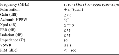
Target antenna specifications include polarization, impedance match, gain, HPBW, front-to-back ratio (FBR), and isolation between slant polarization ports [Reference Guo, Mak, Luk and Lee5]. Cross-polarization level is specified relative to peak co-polarization gain. Passive intermodulation (PIM) products should also be less than −100 dB relative to carrier. PIM occurs when dissimilar metal junctions act like a diode connection at high input power levels. Target antenna specifications are summarized in Table 1.
Table 1. Target antenna specifications.

Proposed antenna structure is illustrated in Fig. 1. The antenna structure is composed of stacked patches separated by air dielectric and fed with L-type plate. Owing to the strict PIM requirement no dielectric material is used in the assembly except the short segment of the feedline. Feedline substrate can also be avoided for single-element design, but if an array of these elements is to be designed, a feed network with appropriate phase difference between the elements can be easily implemented on the substrate. Stacked patches are held together with a plastic screw that goes from top plate to ground. Preliminary shaker-table tests on the antenna showed good mechanical strength. The location of the screw is very close to voltage minima on the driven patch. As opposed to L-type probe, plate feed provides better coupling to driven patch for gain and impedance bandwidth. L-probe feed also suffers from inductive nature of the vertical part which is partly compensated with capacitive coupling of the horizontal part.
Fig. 1. Single-element antenna (L 1 = 22.3 mm, W rp = 48.6 mm, W pp = 56.7 mm, W probe = 29.68 mm, W feed = 3.97 mm, h 1 = 14 mm, h 2 = 21.41 mm, h 3 = 33.3 mm).
As shown in Fig. 1, the driven element is edge-fed. It is known that edge feed increases the input impedance of microstrip antenna to a large value (close to 400 Ω). When the feed is capacitively coupled, the impedance is transformed to a lower value. In order to match this low impedance to 50 Ω, the width of the plate is kept wide. This transformer action also smoothes out large variation on the reactance of the input impedance. This idea, in principle, is similar to aperture coupled antennas where coupling from feed microstrip line to aperture and aperture to driven patch can be modeled as transformers [Reference Bilgiç and Yegin9]. Simulations of the antenna were performed with FEKO, 3D electromagnetic field solver based on method of moments.
Another critical aspect of this design is that the top patch (parasitic patch) is larger than the bottom patch for impedance bandwidth improvement. Aspect ratios (W/L) of both top and bottom patches are optimized in FEKO for gain and impedance match over the target frequency band. While high aspect ratios help impedance match over large frequency band, gain and symmetry in radiation patterns of the antenna become critical.
For +45° and −45° slant polarizations, two different patches with perpendicular orientation is formed as illustrated in Fig. 2. The separation between the elements is determined in order to satisfy the isolation criterion, which is 25 dB. Such low cross-coupling mandates the use of different antenna elements as opposed to single structure with dual polarization. Antenna element can be modified to dual polarization if cross-coupling requirement is relaxed.
Fig. 2. Two-element antenna for dual slant polarization (L spacing = 170 mm).
Prototype antenna is shown in Fig. 3. Low-cost FR4 is used for the feedline. Measurements of the prototype antenna were carried out with a network analyzer (Rohde&Schwarz ZVA40) and the results for input impedance match and cross coupling are shown in Figs 4 and 5. Although measurements were slightly worse than simulation results, both agree reasonably well. Measurements also revealed that the input impedance match, which was defined as VSWR <1.5 (|S11| <−14 dB), was met from 1675 to 2265 MHz where the target was from 1710 to 2170 MHz. Fractional bandwidth was 30%. If high-power transmission requirement is relaxed as in the case of pico- and femto-cell BSAs, then the impedance bandwidth for VSWR <2 is from 1540 to 2335 MHz, which is nearly 41%. Two-port isolation measurements revealed that the cross coupling between the ports was less than 25 dB up to 2635 MHz. Antenna separation between the ports played a critical role in achieving such high isolation over a large frequency band.
Fig. 3. Prototype of the antenna.
Fig. 4. Input reflection coefficient (![]() , measured;
, measured; ![]() , simulated).
, simulated).
Fig. 5. Isolation between the ports (![]() , measured;
, measured; ![]() , simulated).
, simulated).
Presence of plastic screws (3 mm diameter) was first modeled in the simulations and found that they had no influence on any of the antenna characteristics.
One of the polarization ports (+45°) of the prototype antenna was measured in full anechoic chamber to reveal its gain and radiation pattern characteristics. Gain of the antenna is shown in Fig. 6. It was mostly above 7.5 dBi over the target frequency band. Gain fluctuation was within ±0.5 dB over the mean gain. Radiation patterns were measured at three different frequencies (band edges and band center) and are shown in Figs. 7–9. Measured HPBWs were 65°, 86°, and 82° at these frequencies, respectively. Measured and simulated radiation patterns displayed small discrepancy especially at 2170 MHz, which was mainly due to measurement setup. In addition, edge scattering effects in the measurement setup gave rise to slightly broader radiation patterns than simulated ones. However, peak gain and HPBWs overall agree well with those of the simulated ones. Measured FBRs were greater than 15 dB. Cross-polarization levels were also less than −15 dB. We were unable to test the PIM performance of the antenna because the test setup requires two modulated input signals at +43 dBm, triplex filter, and high-power directional coupler. However, the designed antenna is not expected to fail this requirement in its present form. When an array is constructed, presence of unequal power dividers and many feed point contacts could impact PIM performance which needs to be tested and verified for high input power.
Fig. 6. Gain of the single antenna (![]() , measured;
, measured; ![]() , simulated).
, simulated).
Fig. 7. Radiation patterns at 1.71 GHz (![]() , measured Co-Pol gain;
, measured Co-Pol gain; ![]() , simulated Co-Pol gain;
, simulated Co-Pol gain; ![]() , measured X-Pol gain).
, measured X-Pol gain).
Fig. 8. Radiation patterns at 1.94 GHz (![]() , measured Co-Pol gain;
, measured Co-Pol gain; ![]() , simulated Co-Pol gain;
, simulated Co-Pol gain; ![]() , measured X-Pol gain).
, measured X-Pol gain).
Fig. 9. Radiation patterns at 2.17 GHz (![]() , measured Co-Pol gain;
, measured Co-Pol gain; ![]() , simulated Co-Pol gain;
, simulated Co-Pol gain; ![]() , measured X-Pol gain).
, measured X-Pol gain).
III. CONCLUSIONS
Wideband antenna was designed and measured for base station cellular systems covering 1710–2170 MHz frequency band, which is designated for GSM 1800, GSM 1900, and UMTS I cellular systems. Two antenna elements each having slant polarization (+45° or −45°) were formed for dual polarization capability. Measured isolation between the antennas was greater than 25 dB. Antenna gain for each polarization was over 7.5 dBi in the target bandwidth and the gain variation was ±0.5 dB. The antenna structure can be used for BSA arrays as well as pico- and femto-cell small-area cellular communication systems.
Mustafa Murat Bilgiç received B.S. and M.S. degrees in Electrical and Electronics Engineering from Yeditepe University, Istanbul, Turkey in 2002 and 2008. He is currently pursuing his Ph.D. degree. His main research interests are phased array antennas and wideband antennas.
Korkut Yeğin received his B.S. degree in Electrical and Electronics Engineering from Middle East Technical University, Ankara, Turkey in 1992, and M.S. and Ph.D. degrees in Electrical and Computer Engineering, Clemson University, SC, in 1996 and 1999, respectively. He worked as a post-doctoral research fellow at UIUC from 2000 to 2002 and as an Advanced Development Engineer in Delphi Delco Electronics, MI from 2002 to 2007. Since 2007, he is with Yeditepe University Electrical and Electronics Engineering Department, Istanbul, Turkey.