


Introduction
The microwave ablation (MWA) technique has gained considerable attention in recent years due to its advantages over its counterparts [Reference Yang1]. MWA is based on the use of microwaves to eradicate cancerous biological tissues by generating heat within the unhealthy ones [Reference Rubio, Hernandez, Salas, Navarro and Navarro2]. MWA is carried out at high frequencies and there is no need of grounding to propagate electromagnetic waves through the tissue [Reference Acikgoz and Mittra3]. In addition, MWA gives the desired temperature values in a shorter time when compared to the other common technique; namely radiotherapy ablation [Reference Brace4]. MWA is achieved by microwave coaxial antennas (MCA), which operates at 2.45 GHz and can transmit high power into the cancerous tissue [Reference Prakash5]. MCAs, such as monopole [Reference Labonte, Blais, Legault, Ali and Roy6], dipole [Reference Hurter, Reinbold and Lorenz7], slot [Reference Keangin, Rattanadecho and Wessapan8, Reference Wongtrairat, Phasukkit, Tungjitkusolmun and Nantivatana9], and triaxial [Reference Brace, Van Der Weide, Lee and Laeseke10] are preferred in MWA due to their properties such as easy to design and low return loss [Reference Bertram, Yang, Converse, Webster and Mahvi11]. Although MCAs are successful in eradicating the tumor, they exhibit backward heating phenomenon along the antenna, hence they cause damage to the healthy tissue, which is one of the serious problems limiting the use of microwaves as an ablation technique. The reason for the backward heating is the backward surface current, which originates from the slots and propagates along the antenna [Reference Acikgoz and Turer12]. In order to reduce the backward heating problem, there have been numerous studies in the literature. These studies have mainly focused on redesigning the antennas by adding “choke” and/or “sleeve” on the antenna. The operating principle of choked [Reference Longo, Gentili, Cerretelli and Tosoratti13, Reference Lara, Vera, Leija and Gutierrez14], cap-choked [Reference Lin and Wang15], double choked [Reference Acikgoz and Mittra16], and sliding choke [Reference Prakash, Converse, Webster and Mahvi17] antennas is to add a metallic structure on the outer conductor of the antenna to obtain an open circuit along the outer conductor. In sleeve [Reference Prakash, Deng, Converse, Webster, Mahvi and Ferris18] and floating sleeve [Reference Yang, Bertram, Converse, O'Rourke, Webster, Hagness, Will and Mahvi19] antenna designs, it is aimed to prevent backward surface currents by creating a high impedance structure on the outer conductor of the antenna. Although, all mentioned designs reduce the backward heating to some extent, the dimensions of the antenna become impractical to be implemented in MWA. Readers of the present manuscript should be aware that other techniques based on coating the outer conductor with high loss absorbing materials [Reference Li, Li, Wang, Nie and Gong20, Reference Chen, Deng, Zhou, Xie and Zhu21] may give similar results when compared to the results obtained with our graphene-based structure. However, it should be noted that the possibility of using a one-atom thick graphene sheet with extraordinary electronic properties is an important feature for a minimally invasive cancer ablation that is not always achievable by other materials. Although, the growth of a parameter-controlled graphene sheet is still challenging, in the near future, technological progress will certainly permit having more predictable and controlled graphene materials that can be used in similar applications.
In this study, a double slot coaxial antenna coated with one-atom-thick graphene, which behaves as a high impedance surface at microwave frequencies, is considered as a solution to mitigate the backward heating problem. The idea was first proposed by Acikgoz and Mittra [Reference Acikgoz and Mittra3] where an electromagnetic analysis of the proposed design was performed. In this paper, first, an overview of the electronic properties of the graphene sheet and a parametric study aiming to examine the dependence of its conductivity on the chemical potential and the relaxation time is performed. Then, the analysis of graphene coated antenna is extended to thermal analysis and the study of the tissue damage rate. The numerical results indicate that the backward surface current is considerably mitigated while keeping the dimension of the antenna unchanged. It is also observed that the minimum healthy tissue damage can be obtained with the graphene-coated antenna.
Graphene-coated microwave antenna
Mechanical exfoliation of graphite [Reference Novoselov, Geim, Morozov, Jiang, Zhang, Dubonos, Grigorieva and Firsov22], the chemical vapor deposition (CVD) [Reference Somani, Somani and Umeno23], exfoliation of carbon nanotubes [Reference Cano-Márquez, Rodríguez-Macías, Campos-Delgado, Espinosa-González, Tristán-López, Ramíre-González, Cullen, Smith, Terrones and Vega-Cantú24], thermal decomposition [Reference Vázquez de parga, Calleja, Borca, Passeggi, Hinarejos, Guinea and Miranda25] are among the most widely used techniques for the growth of the 2D graphene layer. More often, the CVD is the preferred one due to its easiness and the possibility to tune different parameters such as chamber temperature/pressure, gas flow rate, etc., to control the quality of the graphene deposition. The graphene layer can be grown on a copper foil sheet and then transferred on a targeted substrate. To transfer the graphene, it is first spin coated with polymethyl methacrylate (PMMA), followed with drops of polymethyl siloxane. Then the copper foil is removed by placing copper/graphene/PMMA in aqueous iron chloride solution to leave only graphene and PMMA. Finally, graphene/PMMA is transferred to a targeted surface and then the PMMA is dissolved in acetone [Reference Syarifah Norfaezah, Shafiq Hafly, Siti Fazlina, Meghashama Lim and Noraini26]. Alternatively, authors in [Reference Datta, Gupta, Shafiei, Taylor and Motta27] have directly grown graphene film on a cylindrical copper conductor as in our case.
The conductivity of the graphene is given by the Kubo's formula [Reference Llatser, Kremers, Chigrin, Jornet, Lemme, Cabellos-Aparicio and Alarc Supón28]:

where τ is the relaxation time, μ c is the chemical potential, k b is the Boltzmann constant, $\hbar$ is the Planck constant, T is the room temperature in Kelvin, ω is the angular frequency, and e is the electron charge. The conductivity of the graphene mainly depends on the applied frequency ω, the chemical potential μ c, and the relaxation time τ. The modeling of the graphene sheet is explained in detail in reference [Reference Acikgoz and Mittra16] where it is also shown that the graphene sheet can provide very high impedance as a function of the chemical potential. This behavior can also be seen in Fig. 1(a).

Fig. 1. Conductivity versus chemical potential for different relaxation time (a), Conductivity versus relaxation time for different chemical potential (b).
In fact, charge carriers may be induced in the graphene by the application of an electric field or by chemical doping. In the case of the application of an electric field an electric potential between graphene and a substrate is applied. By changing this gate voltage, carrier's concentration in graphene can be tuned. As a result, this induces a change in the chemical potential of the graphene. The second approach based on the chemical doping of the graphene involves either the use of surface adsorbates or to substitute carbon atoms in the graphene layer by foreign atoms. In the latter case, depending on the type of the incorporated atoms n-type or p-type doped graphene can be obtained [Reference Pinto and Markevich29]. In order to obtain a high impedance surface with low conductivity and to be able to suppress the backward surface current as much as possible, the chemical potential of the graphene should be as close as possible to μ c = 0 eV (Fig. 1(a). However, our designed antenna requires having the graphene layer right on the outer conductor of the coaxial applicator. As such, it is not possible in practice to tune the chemical potential via a gate voltage and therefore, it is unlikely to have 0 eV after deposition. As a consequence, the deposited graphene layer is more prone to have a higher value for its chemical potential leading to a lower surface impedance. As shown in Fig. 1(b), the graphene is also highly dependent on the relaxation time which represent the required time to restore a uniform charge density after a charge distortion is introduced in a material [Reference Abadal, Hosseininejad, Lemme, Bolívar, Solé-Pareta, Alarcón and Cabellos-Aparicio30]. The variation of graphene's conductivity versus the relaxation time is presented in Fig. 1(b). The relaxation time depends, among others, on the carrier mobility which in turn depends on the quality of the graphene [Reference Abadal, Hosseininejad, Lemme, Bolívar, Solé-Pareta, Alarcón and Cabellos-Aparicio30]. Large values of the carrier mobility involve having high quality of material with low defects (large relaxation time) whereas low values imply a material with high defects (low relaxation time). Consequently, changing the relaxation time of the graphene by adding defects would be an alternative strategy to change its conductivity. As stated in [Reference Llatser, Kremers, Chigrin, Jornet, Lemme, Cabellos-Aparicio and Alarc Supón28], values for the relaxation time found in the literature range from 0.01 to 1 ps. As mentioned above, these values correspond to the cases where the graphene layer has high and low defects, respectively. In practice, the deposited graphene layer will not be perfect and it will usually present defects which will lower its relaxation time. Therefore, the relaxation time is expected to be in between these values. To see the effect of these two parameters, i.e. the chemical potential and the relaxation time on the performance of the graphene-coated MCA, we have computed the surface current on the outer conductor of the coaxial antenna and the specific absorption rate (SAR) in the liver tissue (along the antenna) for different chemical potentials and relaxation times. In addition, this parametric study will provide us a range of values of these parameters in which the performance of the examined antenna is still improved compared to the graphene-free MCA. This is particularly important because, besides our inability to tune chemical potential via a gate voltage, the deposition of a graphene layer with a precise relaxation time value is challenging and unpredictable. The results are presented in “Electromagnetic analysis”.
The designed MCA coated with a one-atom-thick graphene layer inserted in liver tissue is shown in Fig. 2. For hygienic and guidance purposes, the antenna is coated with a polytetrafluoroethylene material called catheter. The 3 mm length slots are positioned between 2–5 and 7–10 mm from the shorted end of the antenna. The physical properties of the materials involved in the model are selected from several literature [Reference Yang, Bertram, Converse, O'Rourke, Webster, Hagness, Will and Mahvi19, Reference Bertram, Yang, Converse, Webster and Mahvi31–Reference Jacobsen and Stauffer33] and they are summarized in Table 1.

Fig. 2. Double slot coaxial antenna: perpendicular cut cross-section (a), parallel cut cross-section with its dimensions (b).
Table 1. Tissue and antenna parameters

Electromagnetic analysis
The effect of the one-atom-thick graphene on the efficiency of MCA is numerically investigated first. The efficiency is calculated as the power radiated into the biological tissue (liver) over the input power received by the coaxial antenna. The graphene-free MCA gives an efficiency of 94%. Hence, it is aimed in this study to keep the efficiency of graphene-coated MCA closer to the graphene-free one while reducing the backward surface current. The variation of the efficiency due to the width and the position of the graphene is presented in Fig. 3. It is easily deduced that the efficiency is not affected by the variation of the width of the graphene while keeping its distance to the slot constant (Fig. 3(a)). However, as shown in Fig. 3(b), the efficiency is highly dependent on the position of the graphene, especially when it is placed close to the slot. The lowest efficiency of the MCA is obtained when the graphene sheet is adjacent to the slot. Away from the slot, i.e. after about 20 mm, the efficiency becomes independent of the position. However, as our goal is to reduce the backward heating problem by blocking the propagation of the surface current back to the feed line from the slot, we decided to bring the graphene sheet closer to the slot without lowering the efficiency below 90%. These investigations have resulted in a graphene sheet width of 1 mm positioned at 16 mm from the tip of the MCA. Keeping the width of the graphene sheet as small as possible is important because in practice, larger graphene sheet production would be more difficult and its homogeneity would be at stake [Reference Orofeo, Ago, Hu and Tsuji34]. Thus, the overall efficiency of the graphene-coated MCA is calculated to be 90%.

Fig. 3. The effect of length (a) and position (b) of graphene on the efficiency of MCA.
Since the backward heating problem is due to the surface current propagating on the outer conductor of the MCA, the surface currents density with and without graphene sheet is considered. The surface current density on the outer conductor of the MCAs versus the antenna length is depicted in Fig. 5(a). Although the primary effect of adding graphene layer would be to reduce the surface current after the graphene we calculated the surface current density from the slot to the feed line of the antenna, as shown in Fig. 4(a). It is clearly seen that the MCA coated with the 0 eV graphene material has the lowest surface current density when compared with the graphene-free antenna. In addition, 1 eV graphene, which provides lower impedances at microwave frequencies [Reference Acikgoz and Mittra3], leads to higher surface current density along the antenna when compared with the 0 eV graphene, but this is still low in comparison to the graphene-free antenna. The SAR is evaluated in order to compare the radiation performance of the MCA with and without graphene sheet. The SAR is computed at a radial distance of 1.5 mm from the outer conductor of the MCA (in the liver tissue) and it is depicted in Fig. 5. Two different scenarios are considered. First the relaxation time is kept constant at τ = 0.1 ps and the SAR is calculated for two different chemical potentials, i.e. μ c = 0 eV and μ c = 1 eV (Fig. 5(b)). The plot shows that MCA with graphene damps faster than the graphene-free (normal) antenna while the maximum SAR, which should be high around the slot, remains almost the same. As for the surface current, the electromagnetic energy absorbed in the tissue is quickly damped with the 0 eV graphene and the maximum SAR is located around the slots of the antenna. For a higher chemical potential, i.e. higher conductivity, as expected, the computed SAR is closer to the case without graphene. For the second scenario, we kept the chemical potential constant at μ c = 0.5 eV and calculated the SAR for different relaxation times ranging from τ = 0.1 ps to τ = 0.4 ps (Fig. 5(c)). We notice that, while being closer to the antenna without graphene, the SAR calculated in the tissue is still low. As higher relaxation times lead to higher conductivities (conversely to lower surface impedances), SARs calculated when the relaxation time increases are getting even closer to those of the graphene-free case. The effect of increasing the relaxation time is similar to increasing the chemical potential via a gate voltage or via chemical doping. Our aim in this parametric study being to provide a range of variation for the chemical potential and the relaxation time, we can deduce that these values should be μ c < 0.5 eV and τ < 0.4 ps, respectively. As previously stated, in practice, growing a graphene sheet with exact properties, i.e. chemical potential and relaxation time are challenging and not predictable. Thus, these values will provide guidelines for researchers working in this area.

Fig. 4. Picture depicting where on the antenna the surface current is computed (a), picture depicting where the SAR is computed in the tissue (b).

Fig. 5. Surface current density along the antenna calculated after the slots and toward the feed line (“normal” refers to the graphene-free antenna) (a) and the SAR all the way along the antenna for different chemical potentials with τ = 0.1 ps (b) and for different relaxation times with μc = 0.5 eV (c).
In the following subsections, thermal and damaged tissue rate analysis are presented by changing the chemical potential only. Nonetheless, the same analysis may be performed using the relaxation time and the general behavior of the graphene-coated MCA will be similar to those presented hereafter. In fact, as long as these two parameters are below the upper limits given above, we are secured that that performance of the MCA will be improved.
Thermal analysis
As the main contribution of this work is to study the thermal effect of the graphene covered antenna on the biological tissue, the temperature distribution is investigated via the use of the Penn's equation expressed as in equation (2) [Reference Jiao, Wang, Zhang, Yu, Xue, Lv, Jing, Zhan and Wang35]:

The tissue parameters in the Penn's equation are shown in Table 2. The generation of heat by the electric field is expressed in equation (3).

Table 2. Tissue parameters in penn equation

The relationship between the electric field, SAR and surface current is expressed in equations (4) and (5).


Thus, the Penn's equation can be directly related to the SAR as follow:

The temperature distribution in liver tissue at a radial distance of 1.5 mm away from the MCA is calculated and given in Fig. 6. It is observed that, in accordance with the SAR distribution, the antenna with 0 eV graphene coating gives the highest temperatures at around the slots and it decreases instantly to the low temperatures along the antenna, which indicates that the highest temperature can be delivered to the tissue at around the slots while keeping the minimum damage to the tissue along the antenna. This idea can be best explained when the damaged tissue ratio is examined.
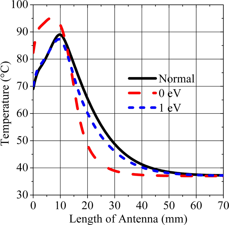
Fig. 6. Temperature distribution in the tissue along the antenna.
Damaged tissue due to electromagnetic energy absorption
Several mechanisms have been proposed for describing the biological tissue damage due to the elevation of the temperature. For instance, a simple model based on multiplying the elevation of temperature ΔT by the time for holding this high temperature is considered [Reference Dewey and Diederich36]. This model has been proven to be inefficient to model tissue damage correctly. A more specific model based on calculating an equivalent time at a reference temperature, where a cell damage is observed, is also considered. The model used in this paper has been largely used in the hyperthermia community. It provides a complex function that relates tissue temperature and time of the temperature elevation to the damaged tissue rate [Reference Prakash5, Reference Chang37]. In this model, the damaged tissue rate is varying exponentially with temperature and linearly with time.
The ratio of the tissue exposed to the electromagnetic energy transferred to the tissue is expressed in equation (7).

In equation (7), Ω(t) is necrotic tissue rate, c(t) is live cell density, c(0) is live cell density before ablation, R is universal gas constant, A frequency factor (s −1), ΔE activation energy for irreversible damage reaction (J/mol) [Reference Borrelli, Thompson, Cain and Dewey38]. It is straightforward from the equation (7) that as the duration of ablation increases the total integral value i.e. the damaged tissue rate increases. indicates that tissue necrosis has occurred. This critical value corresponds to 37% live tissue density, i.e. 63% tissue death [Reference Chang and Nguyen39].
The necrotic tissue rate being defined as above, this latter is computed in the tissue between the slots and after the graphene position (Fig. 7). It can be seen from Fig. 8(a) that MCA with 0 eV graphene coating reaches higher temperature in a shorter time with 100% of tissue damage rate compared to the other types of MCA (Fig. 8(b)). On the other hand, one can deduce from Fig. 9(a) that relatively low temperature increase is obtained beyond the 0 eV graphene coated MCA while having minimum tissue damage (Fig. 9(b)).

Fig. 7. Pictures depicting where the necrotic tissue rate is computed in the tissue, between the slots (a), after the graphene (b).

Fig. 8. Temperature distribution (a), tissue damaged rate (b), at a 1.5 mm distance, between slots.

Fig. 9. Temperature versus time (a), tissue damaged rate (b), computed at a radial distance of 1.5 mm, after the graphene.
Figure 10 shows a 2D distribution of the damaged tissue ratio (necrotic tissue ratio) caused by the electromagnetic energy radiated from the graphene-free and 0 eV graphene-coated MCAs. It can be easily observed that the backward reaction phenomenon is significantly reduced with respect to the graphene-free antenna. Thus, healthy tissue is prevented from damage throughout the antenna and a more spherical ablation zone around the slots is achieved.

Fig. 10. 2D damage tissue rate: without graphene (a), with 0 eV graphene-coated antenna (b).
Finally, the sleeve and choke antennas, which are widely used in MWA to reduce surface currents and thus to minimize backward heating, have been modeled in order to compare the performance of the proposed antenna graphene coated with μ c = 0 eV, τ = 0.1 ps. The dimensions and material properties of single slot sleeve and choke antennas are obtained from the papers [Reference Prakash, Deng, Converse, Webster, Mahvi and Ferris18, Reference Yang, Bertram, Converse, O'Rourke, Webster, Hagness, Will and Mahvi19]. The comparison between antennas is performed in terms of SAR (Fig. 11(a)) and temperature (Fig. 11(b)) distributions along the antennas. In contrast to these antenna structures, the graphene-coated MCA concentrates more the energy around the slots and damps immediately right after the slots. Hence the healthy tissue along the antenna is prevented from damage and a more spherical ablation zone around the slots is achieved with the proposed graphene-based antenna (Fig. 12).

Fig. 11. SAR distribution (a), Temperature distribution (b), at 1.5 mm distance from antennas.

Fig. 12. 2D damaged tissue ratio: 0 eV Graphene (a), Choke (b), Sleeve (c).
Conclusion
In this paper, a novel structure based on the use of a 2D material namely graphene as a high impedance surface for mitigating the propagation of surface currents on the outer conductor of a MCA has been presented and some numerical results have been discussed. A parametric study has been carried out to find a range of values for the chemical potential and the relaxation time. It is concluded that, the chemical potential and the relaxation time of the graphene should be μ c < 0.5 eV and τ < 0.4 ps in order to have substantial improvement in comparison to the performance of the graphene-free antenna. Furthermore, a thermal analysis of the structure demonstrated that the antenna covered with a graphene layer is capable of reducing surface currents and thus decreasing the elevation of the temperature in healthy tissue. Consequently, a more spherical ablation zone may be obtained with the application of the microwave heating antenna. Moreover, due to the restriction of the temperature elevation only in the unhealthy tissue region, a rapid tissue necrosis is observed. Graphene-coated antenna is also compared with some common structures to address this problem such as choke and sleeve antennas. Results are encouraging in such a way that the proposed antenna outperforms the ones given in the literature. Experimental works are needed to confirm the results presented in this paper before possible clinical trials.
Acknowledgement
The authors would like to thank the support from the Scientific and Technological Research Council of Turkey (TUBITAK) ARDEB-3001 Grant No: 116E298.
 Burak Uzman received the B.S. and M.S degrees in electrical and electronics engineering from the KTO Karatay University, Konya, Turkey. He is currently working as an antenna engineer at Engitek Ltd. His research interests include antennas for microwave cancer and antennas for mobile communication.
 Adem Yilmaz received the B.S. and M.S degrees in electrical and electronics engineering from the University of Gaziantep and Ankara Yildirim Beyazit University, respectively. He is currently pursuing the Ph.D. degree at Ankara Yildirim Beyazit University, Turkey. From 2010 to 2011, he was a researcher at Goethe Frankfurt University, Germany. Since 2011, he has been a Research Assistant at KTO Karatay University. His research interests include design and characterization of periodic structures, antennas for microwave cancer, computational electromagnetics, and the theory of characteristic modes.
 Hulusi Acikgoz received the B.S. and Master degrees in applied physics from the Paris-Est Marne-La-Val Supée University, France, and the Ph.D. degree from the Pierre and Marie Curie University (UPMC-Paris IV), Paris, France, in 2008 in electrical engineering. He has been a teaching assistant at UPMC-Paris IV in 2009–2010. After a year of post-doctoral research at the L2E (Laboratoire d'Electronique et d'Electromagn Supétisme) in computational electromagnetic dosimetry, he joined the KTO Karatay University, Konya, Turkey, in 2011, as an assistant professor. He spent a year as visiting scholar with Dr. Raj Mittra's research group at Pennsylvania State and Central Florida Universities, USA. His research interests include microwave characterization of dielectric materials, electromagnetic dosimetry, homogenization, antennas for microwave cancer ablation, high impedance surfaces, graphene applications in EM, and statistical analysis of EM structures.
 Raj Mittra (LF’96) was a Professor of electrical and computer engineering, Penn State, State College, PA, USA, from 1996 to 2015. He was a Professor with the Electrical and Computer Engineering, University of Illinois at Urbana–Champaign, Champaign, IL, USA, from 1957 to 1996. He is currently a Professor with the Department of Electrical Engineering and Computer Science, University of Central Florida, Orlando, FL, USA, where he is currently the Director with the Electromagnetic Communication Laboratory. He is currently the Hi-Ci Professor with King Abdulaziz University, Jeddah, Saudi Arabia. Mittra was a recipient of the Guggenheim Fellowship Award in 1965, the IEEE Centennial Medal in 1984, the IEEE Millennium medal in 2000, the IEEE/AP-S Distinguished Achievement Award in 2002, the Chen-To Tai Education Award in 2004 and the IEEE Electromagnetics Award in 2006, and the IEEE James H. Mulligan Award in 2011. He is a PastPresident of AP-S, and he has served as the Editor of the Transactions of the Antennas and Propagation Society. He founded the e-Journal FERMAT and has been serving as the co-editor-in-chief of the same. He is a Principal Scientist and President of RM Associates, a consulting company founded in 1980, which provides services to industrial and governmental organizations, both in the USA and abroad.


