


Polytetrafluoroethylene is a superior self-lubricating material with an especially low friction coefficient, high thermal stability and outstanding chemical inertness. However, its insufficient mechanical properties, especially its poor wear behaviour, have seriously hindered its further development in high-performance materials. Recently, it has been proposed that the key to obtaining advanced composite materials is the nano-sized filler introduced into the polymer matrix. As for the polymer composites, the dispersion of nanoparticles in the polymer matrix was deemed to be difficult, which affects the stress transfer from polymers to nanoparticles (Ren et al., Reference Ren, Liang and Zhang2009; Liu et al., Reference Liu, Jia, Jia and Zhou2014). Successfully overcoming this problem usually includes the functionalization of nanoparticles so that they remain at the nanometre scale in order to achieve desirable chemical and physical characteristics.
The functionalization of nano-sized fillers has been studied extensively in order to address their inherent agglomeration and the poor compatibility between the polymer matrix and fillers. Previous studies have shown that the functionalization of nanoparticles is important because it improves their dispersion and compatibility. The wear behaviour of the PTFE composites filled with modified fillers with 0.13–1.00 wt.% of nanoparticle loading was improved by 6000–10,000 times relative to pure PTFE (Burris et al., Reference Burris, Zhao, Duncan, Lowitz, Perry, Schadler and Sawyer2009). The rare earth- modified carbon nanotube (CNT)/PTFE nanocomposite had greater thermal stability and better mechanical properties than the pristine CNT/PTFE nanocomposite (Cheng & Cheng, Reference Cheng and Cheng2013). The effects of silane coupling agents on the properties of the SiO2-filled PTFE composites have also been investigated. Due to compound coupling agent-modified SiO2 particles being well dispersed in PTFE polymers, the polymer composites exhibited improvements in mechanical, frictional and thermal properties (Yuan et al., Reference Yuan, Lin, Yu, Tang, Li and Zhang2017).
Halloysite nanotubes are naturally occurring aluminosilicates of the kaolin group (Al2(OH)4Si2O5·nH2O) with nanotubular structures. As economically available pristine materials, HNT fillers have many promising applications in polymers due to their inherent hollow nanotube structure and the different chemistries of the outer and inner parts of the nanotubes (Ismail et al., Reference Ismail, Pasbakhsh, Ahmad Fauzi and Bakar2008; Liu et al., Reference Liu, Guo, Du, Chen and Jia2009; Pasbakhsh et al., Reference Pasbakhsh, Ismail, Ahmad Fauzi and Bakar2009, Reference Pasbakhsh, Ismail, Ahmad Fauzi and Bakar2010; Rooj et al., Reference Rooj, Das, Thakur, Mahaling, Bhowmick and Heinrich2010; Lvov & Abdullayev, Reference Lvov and Abdullayev2013). In general, HNTs vary in length from the submicron scale to several microns, in external diameter from ~30 to 190 nm and in internal diameter from ~10 to 100 nm (Yuan et al., Reference Yuan, Southon, Liu, Green and Hook2008). Halloysite nanotubes are promising fillers for HNT–polymer nanocomposites due to the large specific surface area, high aspect ratio, good dispersion and excellent mechanical properties (Yuan et al., Reference Yuan, Tan and Annabi-Bergaya2015). Interestingly, HNTs are morphologically similar to multi-walled CNTs that are technologically demanding to produce in bulk and consequently are very expensive. Moreover, in contrast to the inert walls of CNTs, the surfaces and edges of HNTs contain hydroxyl groups, providing an opportunity for further modification with various organic compounds. Therefore, the much cheaper, natural and more ecological HNTs with unique combinations of tubular nanostructure, rich functionality and high aspect ratio may replace the more expensive CNTs in high-performance and multifunctional polymer nanocomposites (Liu et al., Reference Liu, Jia, Jia and Zhou2014). Hence, HNTs have become ideal reinforcement agents for fabricating polymeric composites with improved mechanical performance (Ismail et al., Reference Ismail, Pasbakhsh, Ahmad Fauzi and Bakar2008; Jia et al., Reference Jia, Luo, Guo, Yang, Du and Jia2009).
The objective of surface modification is to introduce functional groups onto the external surface, the interlayer surface and the internal lumen surface of HNTs, which would be performed by either physical or chemical methods. The modification of the outer surface of HNTs aims to improve the dispersibility of nanotubes in the polymer matrix. The modification of HNTs with γ-aminopropyltriethoxysilane (APTES) modified the surface chemistry of HNTs, enabling applications in nanocomposites (Yuan et al., Reference Yuan, Southon, Liu, Green and Hook2008). The notched izod impact strength of polyvinyl chloride (PVC) filled with PMMA-grafted HNTs at 3 phr (per hundreds of resin) was increased nearly two-fold compared to pure PVC (Liu et al., Reference Liu, Luo, Jia, Zhong, Li, Guo and Jia2011). The tensile modulus and strength of fabricated polylactic acid (PLA)/modified HNT nanocomposites increased by 3 and 1.34 times compared with PLA upon loading with 10 and 1 wt.% of HNT loading, respectively (Dong et al., Reference Dong, Marshall, Haroosh, Mohammadzadehmoghadam, Liu, Qi and Lau2015). In addition, the hardness of unsaturated polyester (UPE) composites increased by 1.36 times compared to pure UPE after the addition of silane-treated HNTs (Albdiry & Yousif, Reference Albdiry and Yousif2013). Hence, the modification of HNTs improved the mechanical properties of polymers. More recently, the present authors' research group prepared HNT-filled polyvinyl alcohol (PVA), polyacrylonitrile (PAN) and PMMA composite nanofibres with preferable performance (Cheng et al., Reference Cheng and Qin2016, Reference Cheng, Qin, Liu and Qin2017; Liu et al., Reference Liu, Qin, Qin and Cheng2017).
The surface modification of HNTs with significantly improved dispersion properties might be achieved by either physical modification (electrostatic attraction) or chemical modification (silane coupling and surface graft polymerization). Uniformly dispersed HNTs were obtained using SDS to disperse the halloysite suspension (electrostatic attraction) (Lun et al., Reference Lun, Ouyang and Yang2014). Modification of the hydroxyl functional groups to produce carboxylic acid-functionalized HNT involved controlled aggregation/dispersion properties of HNT-COOH by adjusting the pH of the solution (silane coupling) (Joo et al., Reference Joo, Jeon and Sang2012). Halloysite nanotubes grafted with PMMA via radical polymerization improved the toughness, strength and modulus of PVC (surface graft polymerization) (Liu et al., Reference Liu, Luo, Jia, Zhong, Li, Guo and Jia2011). Previous studies have used three different approaches to dispersion of HNT powder. These techniques for modifying HNTs might bring about various effects depending on the particular structure and composition of PTFE.
In this paper, pristine HNTs were functionalized using three different modifiers and the modified HNTs were characterized by various methods. The PTFE nanocomposites filled with unmodified or modified HNTs were prepared with cool compression moulding. The mechanical and tribological properties of PTFE and PTFE nanocomposites were also investigated extensively. Furthermore, the anti-wear mechanism of the nanocomposites was assessed by examining their worn surfaces and wear debris.
EXPERIMENTAL SECTION
Materials
Sodium dodecyl sulfate (SDS), methyl methacrylate (MMA), potassium persulfate (KPS), 3-trimethoxysilyl-propyl methacrylate (MPS), toluene, dimethylformamide (DMF), triethylamine and APTES of analytical grade were purchased from Sinopharm Chemical Reagent Co., Ltd. A PTFE powder with an average 25 µm particle size was purchased from Shanghai 3F New Material Co., Ltd. The pristine HNTs were purchased from Yangzhou Xigema New Material Co., Ltd.
Purification of HNTs was carried out by repeated acid-washing. An amount of HNT powder was dispersed in 0.5 wt.% of HCl aqueous solution under vigorous stirring at 60°C for 6 h, followed by centrifugation and acid-washing at least three times. Finally, the purified product was dried at 60°C. The morphology of the purified HNTs with few impurities is illustrated in Fig. 1a1,a2. The chemical composition of the acid-treated HNTs is: SiO2 (54.51 wt.%), Al2O3 (28.84 wt.%), Fe2O3 (2.96 wt.%), CaO (4.25 wt.%), MgO (0.21 wt.%), Na2O (1.45 wt.%), K2O (2.89 wt.%), TiO2 (1.39 wt.%), ZnO (0.22 wt.%), ZrO2 (0.45 wt.%), SO3 (0.65 wt.%) and others (2.18 wt.%).
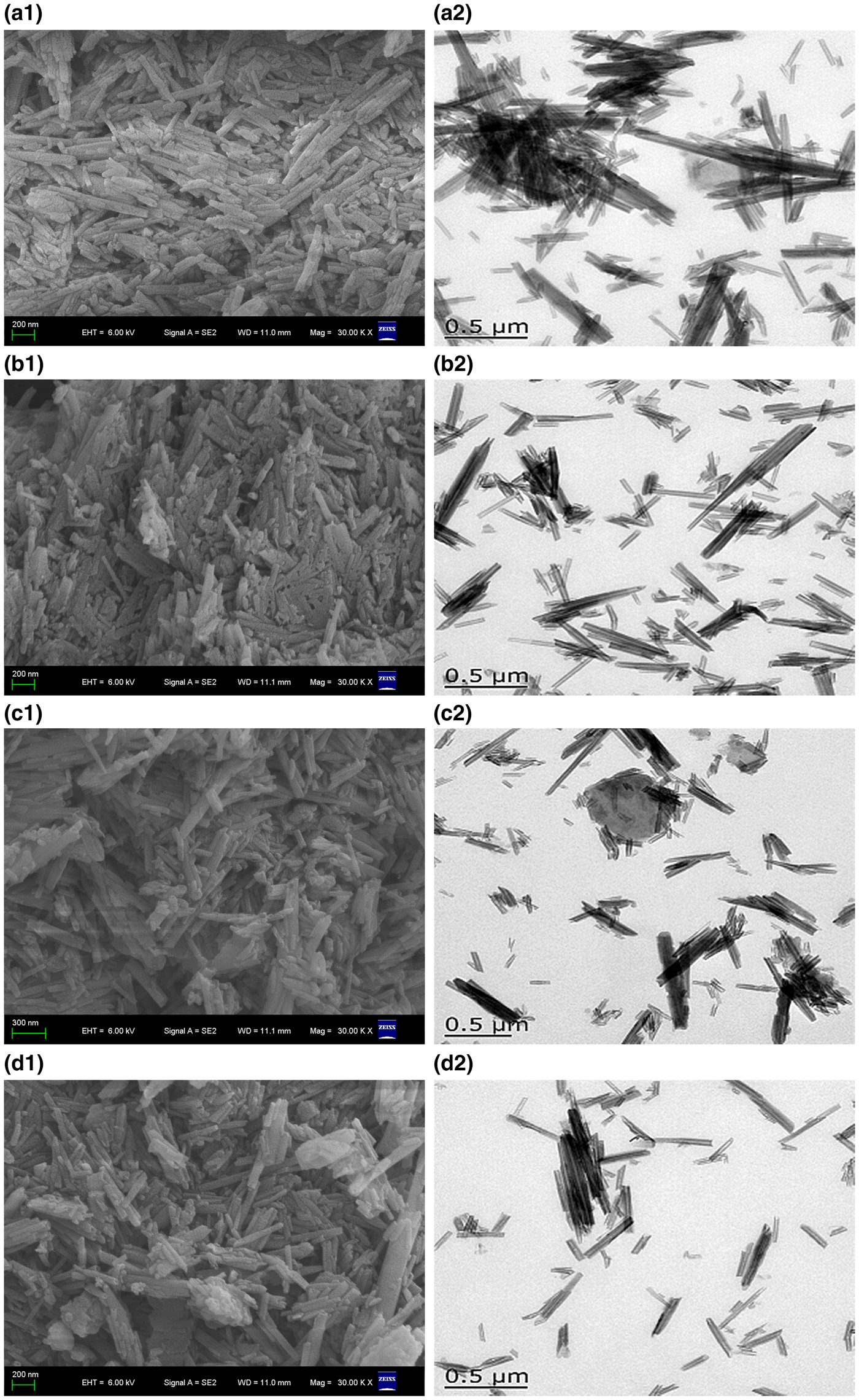
Fig. 1. SEM and TEM images of the pristine HNTs and modified HNTs: (a1,a2) pristine HNTs; (b1,b2) HNT-SDS; (c1,c2) HNT-PMMA; (d1,d2) HNT-COOH.
Surface functionalization of HNTs
Modification of HNT surfaces was done using three different modifiers. The detailed preparation method is given in the following sections.
HNT-PMMA
Halloysite nanotubes were first modified by an MPS coupling agent. The required volumes of MPS were added to the toluene dispersions containing HNTs at 110°C under stirring conditions for 10 h. The suspensions were dried at 50°C under vacuum for 24 h, and the MPS-functionalized HNTs were extracted by a Soxhlet extractor for 12 h with toluene. The product was finally dried at 50°C under vacuum for 24 h. The amount of MPS grafted onto the HNT surfaces was evaluated by thermogravimetric analysis (TGA). The polymerization of MMA in the presence of MPS-functionalized HNTs was carried out in a four-necked flask equipped with a reflux condenser, a stirrer, a thermometer and a nitrogen inlet. First, the functionalized HNTs were dispersed ultrasonically in water containing SDS, and then they were heated under constant stirring conditions under nitrogen flow. At ~80°C, the aqueous solution of initiator KPS was added. After 10 min, 10 wt.% MMA (based on HNTs) was added and reacted at 80°C for 3 h. The polymerization products were extracted with chloroform for 24 h in a Soxhlet apparatus to remove the ungrafted polymer after emulsion breakage and purification. The PMMA-grafted HNTs obtained were dried at 50°C under vacuum to a constant weight (Liu et al., Reference Liu, Luo, Jia, Zhong, Li, Guo and Jia2011).
HNT-SDS
A total of 5 g of purified HNTs and 0.61 g of SDS were added to 0.5 L deionized water and stirred for 5 h in an emulsifying machine at 4000 rpm to form a HNT-SDS suspension (Lun et al., Reference Lun, Ouyang and Yang2014).
HNT-COOH
Halloysite nanotubes modified with amino-groups (HNT-NH2) were synthesized using pure HNT as follows: the HNTs were dispersed in 100 mL of toluene by sonication for 2 h and stirring (400 rpm) for 2 h. Then, 3 mL of triethylamine and APTES solution were added to the HNT solution, and the mixture was stirred for 1 day at 80°C in a nitrogen atmosphere. The HNT-NH2 was washed several times with distilled water and ethanol, then collected and dried at 50°C under vacuum at 1.1 Pa. The HNT-COOH was synthesized from HNT-NH2. 2 mL of 0.1 M succinic anhydride and dry HNT-NH2 was mixed in DMF, and the mixture was stirred for 1 day. The HNT-COOH collected was dried in a vacuum oven at 50°C and 3.6 mPa (Joo et al., Reference Joo, Jeon and Sang2012).
Preparation of HNT/PTFE nanocomposites
The PTFE and pristine or modified HNT powders were mixed mechanically. The specimens were prepared by compression moulding at 10 MPa. Then, the specimens were sintered at 375°C for 2 h and finally cooled to ambient temperature. The mass fraction of HNTs in the nanocomposites was 2 wt.%. The as-prepared nanocomposites were denoted as pristine HNT/PTFE, SDS-HNT/PTFE, PMMA-HNT/PTFE and COOH-HNT/PTFE.
Mechanical and tribological properties
The standard tensile and flexural properties were determined on 42.8 mm × 5.9 mm × 0.8 mm specimens with an electronic universal testing machine (WDW-5, Shanghai Hualong Test Instrument Factory) controlled by computer at a 50 mm/min tensile speed. Each sample was tested five times and the mean value was recorded. The thickness of each specimen was calculated from the average of five measurements taken along the gauge length with a digital micrometer.
The tribological and wear behaviour tests were performed in a MMW-1 machine (Jinan Chenda Ltd Co., China) on a ring-on-ring friction and wear tester. A schematic diagram of the frictional counterparts is shown in Fig. 2. The testing was carried out under dry friction for 60 min at constant environmental conditions at a rotating speed of 200 rpm and a load of 200 N. Each experiment was performed in triplicate and the average values recorded. The friction coefficient was obtained automatically. The wear rate, K (cm3/h), was calculated according to equations 1 and 2:
 $$K\; = {\rm} {\rm d}V\! {/}{\rm d}t$$
 $$V\; = \; \Delta m {/}{\rm \rho} $$
where dV and dt are the volume loss and the sliding time, respectively, Δm is the mass loss (mg) and ρ is the density of PTFE composites in g/cm3.
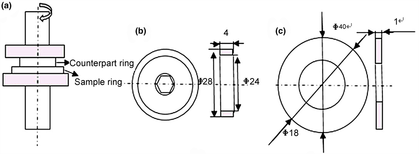
Fig. 2. Schematic diagram of the wear tester: (a) ring-on-ring contact; (b) counterpart ring; (c) sample ring.
Characterization of the nanocomposites
The X-ray diffraction (XRD) analysis was performed with a Cu-Kα radiation source using a Bruker-AXS D8 Advance (Germany) instrument with background noise <0.4 cycles per second, 40 kV, 40 mA, scanning speed 0.1°/s and scanning range 5–70°2θ. The FTIR spectra of the nanocomposites were recorded on a Cary 610/670 micro IR spectrometer with a resolution of 4 cm−1 in the range of 4000–400 cm–1 using KBr wafers containing 0.5% of sample with single reflection automatic target recognition (ATR) attachment (Varian, USA). The SEM images were recorded with a Hitachi S-4800 (Japan) scanning electron microscope at an acceleration voltage of 10 kV on gold-coated samples. The water contact angle was measured with a drop shape analyser DSA 100 instrument at 25°C. The contact angle was measured just after deposition onto the substrate.
RESULTS AND DISCUSSION
Characterization of the modified HNTs
Although the HNTs show good dispersion in aqueous solution because of the negatively charged external hydrophilic surface, it remains difficult to achieve good dispersion in the polymer matrix because they HNTs readily form micron-sized aggregates. Surface modification of HNTs was crucial to improve effectively the dispersion of HNTs in the polymer matrix and the interfacial interactions (Yuan et al., Reference Yuan, Tan and Annabi-Bergaya2015). Figure 3 shows the FTIR spectra of the pristine HNTs and modified HNTs. The absorption bands at 468 and 560 cm–1 in the HNT spectrum are assigned to Si–O–Si and Al–O–Si vibrations, respectively, and the bands at 1039 and 911 cm–1 are assigned to Si–O stretching and deformation of the inner hydroxyl groups, respectively. The weak absorption band at 1650 cm–1 is attributed to O–H deformation of adsorbed water. The O–H-stretching vibrations of inner-surface Al–OH groups and inner-surface Al–OH groups lie at 3703 and 3622 cm–1, respectively (Albdiry et al., Reference Albdiry and Yousif2013).

Fig. 3. FTIR spectra of the pure and modified HNTs: (a) pristine HNTs; (b) HNT-SDS; (c) HNT-PMMA; (d) HNT-COOH.
The spectrum of the SDS-modified HNTs (Fig. 3b) displays a distinct characteristic band at 1179 cm–1 originating from S = O stretching (Ng et al., Reference Ng, Subari, Marie, Mukti and Juan2013; Lun et al., Reference Lun, Ouyang and Yang2014) and two strong characteristic bands at 1466 and 2922 cm–1 attributed to C–H symmetric stretching and asymmetric stretching, respectively (Pasbakhsh et al., Reference Pasbakhsh, Ismail, Ahmad Fauzi and Bakar2010; Lun et al., Reference Lun, Ouyang and Yang2014). In the spectrum of the PMMA-grafted HNTs (Fig. 3c), the characteristic absorption band at ~1732 cm–1 is attributed to the C = O vibration of PMMA, indicating that the PMMA molecules are covalently bonded on the surfaces of HNTs through graft polymerization (Liu et al., Reference Liu, Luo, Jia, Zhong, Li, Guo and Jia2011). Regarding the spectrum of HNT-COOH (Fig. 3d), the weak absorption bands in the range of 2859–3352 cm–1 are attributed to the N–H and COOH vibrations (Joo et al., Reference Joo, Jeon and Sang2012), suggesting the surface modification of HNTs by carboxylic acid (HNT-COOH).
Figure 1 shows the TEM and SEM images of the pristine HNTs and modified HNTs. The pristine HNTs exhibit a typical tubular shape and hollow lumen structure (Fig. 1a1,a2). Their average length is ~0.5–2.0 µm and the outer diameter is ~50 nm. No impurities were observed. Agglomeration of the pristine HNTs is intense. The modified HNTs display better dispersion than the pristine HNTs. The SDS-modified HNTs display fewer agglomeration clusters than the three types of modified HNTs (Fig. 1b1,b2). The limited agglomeration of the modified HNTs helped to improve the compatibility and dispersibility between HNTs and the PTFE matrix.
The contact angles of pristine HNTs, HNT-SDS, HNT-PMMA and HNT-COOH are 14.6°, 30.8°, 80.9° and 15.5°, respectively (Fig. 4), indicating that the hydrophobicity of the modified HNTs was improved due to the organic functionalization of the surface. The PMMA-modified HNTs have the greatest contact angle, indicating that the hydrophobicity of the PMMA-modified HNTs is the best among the three types of modified HNTs, in accord with Lun et al. (Reference Lun, Ouyang and Yang2014).

Fig. 4. Water contact angles of pure and modified HNTs: (a) HNTs; (b) HNT-SDS; (c) HNT-PMMA; (d) HNTs-COOH.
Figure 5 shows the SEM images of the broken surfaces of PTFE and the PTFE nanocomposites. The fibre structure of the surface of the cross-section of the PTFE slab was probably caused by fracturing when the PTFE specimen was broken (Fig. 5a). This structure was not observed on the surface of the cross-section of the HNT/PTFE nanocomposite (Fig. 5b–e). A crystal of PTFE consisting of macromolecular chains has a ribbon-like structure and smooth surface. Therefore, the cross-section morphology of pure PTFE shows many ductile microfibrils and drawn ligaments (Brown et al., Reference Brown, Rae, Orler, Gray and Dattelbaum2006). Because the outer diameter of the HNTs is 50 nm (i.e. of the same order of magnitude as the dimensions of single PTFE crystals), HNTs can intertwine with PTFE crystals. After filling with the pristine HNTs, the nanocomposite contains many HNT aggregates (marked with white circles in Fig. 5b,d), indicating poor dispersion of the pristine HNTs in the PTFE matrix (Fig. 5b). Due to Van der Waals bonding, the nanoparticles form agglomerated clusters in the polymeric matrix during fabrication (Thostenson et al., Reference Thostenson, Li and Chou2005). Surface treatment of fillers with appropriate modifiers might improve the PTFE nanocomposites’ interfacial strength and the dispersion of fillers in the composites (Chen et al., Reference Chen, Lin and Lee2004). After filling with the modified HNTs, few HNT aggregates were found in the matrix, indicating that the dispersibility and compatibility of the modified HNTs in PTFE were improved considerably. In addition, a few stretched HNTs are present in the images, suggesting that the binding force of the interface between HNTs and PTFE is weak. Compared to the pristine PTFE, the ductile microfibrils and drawn ligaments disappear in the broken surfaces of the PMMA-HNT/PTFE nanocomposites. However, the morphologies of the SDS- and COOH-HNT/PTFE nanocomposites still show some ductile microfibrils and drawn ligaments, indicating that these nanocomposites have greater tensile strength. Because of the stronger mechanical properties and higher aspect ratio, the HNTs might reinforce HNT/PTFE nanocomposites significantly, and thus protect the crystal structure of PTFE from destruction during the friction test. This is the reason for the absence of the fibre structure on the surface of the cross-section of the HNT/PTFE nanocomposites. HNTs effectively impede this drawing-out of PTFE crystals, and thus improve the wear resistance of the HNT/PTFE nanocomposites significantly.
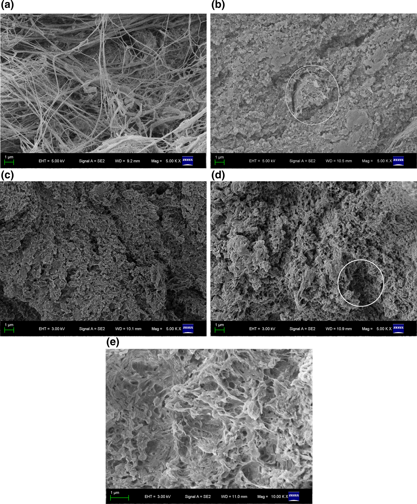
Fig. 5. SEM images of the broken surfaces of pure PTFE and HNT/PTFE nanocomposites: (a) PTFE; (b) pristine HNTs; (c) HNT-SDS; (d) HNT-PMMA; (e) HNT-COOH.
Aggregation and dispersion of HNT particles are very important for their applications. The HNT-SDS, -PMMA and -COOH represent completely different dispersion mechanisms. The SDS modification of HNTs by electrostatic attraction and the COOH modification of HNTs by silane coupling both exhibited better dispersion in water because they both had higher hydrophilicity. In contrast, the modification of HNTs by PMMA grafting increased surface hydrophobicity. It is suggested that the difference in dispersibility of the PTFE polymer should be ascribed to the solubility of PMMA in PTFE polymer due to its higher hydrophobicity.
Mechanical and tribological performance of HNT/PTFE nanocomposites
Better dispersion and compatibility are convenient and efficient for the load transfer between the fillers and the polymer matrix. Figure 6 shows the tensile stress and elongation at break of PTFE and PTFE nanocomposites. The interfacial failure of pristine HNT/PTFE nanocomposites is more pronounced, yielding a lower tensile stress than PTFE. As expected, the tensile stresses of the SDS- and COOH-HNT/PTFE nanocomposites are higher by 2.4–4.0 MPa than those of PTFE and the pristine HNT/PTFE nanocomposite (Fig. 6a). Although the PMMA-HNT/PTFE nanocomposite shows a decline in tensile stress relative to PTFE, it is greater than that of the pristine HNT/PTFE nanocomposite. The SDS- and COOH-modified HNT/PTFE nanocomposites showed excellent mechanical processing abilities due to the substantial improvement in the dispersion of HNTs by virtue of the strong interfacial interactions. These modifications increased the interactions between HNTs and PTFE and the degree of dispersion of HNTs in the PTFE matrix, thereby improving the tensile strength and the tensile modulus. The improvement in the mechanical behaviour of the PTFE nanocomposites is attributed to the presence of the reinforcing filler HNTs, to which load is efficiently transferred from the polymers. The presence of HNT nanofillers causes stress concentration at the filler surface. However, the HNT/PTFE nanocomposites display poorer elongation at break than pure PTFE (Fig. 6b). The addition of HNTs to the PTFE matrix might increase the stiffness of nanocomposites, which decreases the elongation at break. These results suggest that the HNT/PTFE nanocomposites become more brittle than pure PTFE due to micro-voids forming around the nanotubes during tensile testing.
Fig. 6. (a) Tensile stress and (b) elongation at break of PTFE and HNT/PTFE nanocomposites: a = PTFE; b = pristine HNTs; c = HNT-SDS; d = HNT-PMMA; e = HNT-COOH.
The Young moduli of PTFE and the HNT/PTFE nanocomposites are depicted in Fig. 7. The Young modulus of the pristine HNT/PTFE nanocomposite increased by 45.45% compared to pure PTFE. Surprisingly, the Young moduli of the modified HNT/PTFE nanocomposites increased substantially by 226% (HNT-SDS), 274% (HNT-PMMA) and 263% (HNT-COOH), respectively, compared with that of pure PTFE. These results suggest that the modified HNT/PTFE nanocomposites display less deformation under external force, which is important for the application of PTFE. Hence, the modification of HNTs by a grafting reaction with modifiers allowed for a better interface and rendered them as effective reinforcing fillers for PTFE.
Fig. 7. Young moduli of PTFE and HNT/PTFE nanocomposites: a = PTFE; b = pristine HNTs; c = HNT-SDS; d = HNT-PMMA; e = HNT-COOH.
Figure 8 displays the friction coefficients and volume wear rates of PTFE and PTFE nanocomposites. The friction coefficients depend on sliding time (Fig. 8a). The friction coefficient of pure PTFE decreases with increasing sliding time, up to a value of 0.14 as the sample became unsuitable for further testing. The PTFE polymer has a low friction coefficient, and therefore provides dry sliding. The explanation for the low friction coefficient is the presence of a thin, highly oriented transfer film as well as orientation in the wearing body. The pristine HNT/PTFE nanocomposite shows a similar trend to that of pure PTFE. In contrast, the friction coefficients of the modified HNT/PTFE nanocomposites vary considerably with sliding time. In the first 1000 s, the friction coefficient decreases rapidly, increasing thereafter before reaching a plateau at 1500–3500 s. At the end of the experiment, the friction coefficients of the modified HNT/PTFE nanocomposites are significantly greater than those of the pure PTFE and the pristine HNT/PTFE nanocomposite. It is suggested that the friction coefficients increased due to the presence of HNT fillers. More interestingly, the friction coefficient of the pristine HNT/PTFE nanocomposite along with friction time show similar trends to those of pure PTFE. It is suggested that the pristine HNTs, which were poorly dispersed in PTFE, did not modify the structure of PTFE by much.
Fig. 8. (a) Friction coefficient and (b) wear rate of PTFE and HNT/PTFE nanocomposites: a = PTFE; b = pristine HNTs; c = HNT-SDS; d = HNT-PMMA; e = HNT-COOH.
During the so-called run-in period at the beginning of the sliding, all of the nanocomposites exhibited relatively high coefficients of friction against 45 carbon steel, followed by steady-state sliding motion until the friction coefficient remained unchanged due to the formation of steady transfer films on the friction pairs following repetitive sliding action. The transfer film formed on the sliding pairs during sliding play an important role in the tribological behaviour of polymers. However, the increase in the friction coefficient for the modified HNT/PTFE nanocomposites is ascribed to the rough surface of HNTs against the transfer film. The decreasing friction coefficient of the pristine HNT/PTFE nanocomposite is attributed to the poor dispersion of HNTs in the PTFE matrix, which results in few HNTs being present in the transfer film. The pure PTFE displayed significant wear resistance during testing (Fig. 8b). The wear mechanism of PTFE lies in the slipping and rupturing of the macromolecular chains of PTFE under the action of an external force, and these chains are then pulled out onto the surface of the crystalline region and are transferred as slices to the surface of the friction disk. These PTFE slices form the transfer film on the surface of the friction disk (Blanchet & Kennedy, Reference Blanchet and Kennedy1992). Transfer films play a very important role in the tribology of polymers; the formation of thin and uniform transfer films may explain low wear rates (Ye et al., Reference Ye, Khare and Burris2013). The film from pure PTFE has poor viscosity, stability and thermal conductivity, despite its good lubrication effect. Thus, it falls easily from the friction surface, due to the high temperatures generated during the friction process, which lead to the high wear rate of pure PTFE (Blanchet & Kennedy, Reference Blanchet and Kennedy1992; Li et al., Reference Li, Sun, Hu and Li1992, Reference Li, You, Li and Deng2013).
After filling with pristine HNTs, the wear resistance of the nanocomposite is clearly improved by ~50% as compared to pure PTFE. This behaviour is attributed to the presence of the HNTs, which acted as effective barriers preventing large-scale fragmentation of PTFE. First, the hard fillers bear the load, resulting in the reduction of friction to the PTFE matrix. Second, the fillers may assist in packing PTFE macromolecular chains and preventing them from slipping and breaking. However, the smaller the size of filler particles, the larger their specific surface area and the more likely that the particles will agglomerate. Without special surface treatment, the unique nano-effect of nanoparticles cannot be utilized fully (Asbeck, Reference Asbeck1987). Hence, the wear rates of the modified HNT/PTFE nanocomposites were reduced by 9–40 times relative to the pristine HNT/PTFE. When the PTFE nanocomposites were sliding against the steel counterpart, the load was transferred to the HNTs. The modified HNTs are dispersed more efficiently in the PTFE matrix than pristine HNTs, which led to better stress transfer and slowed the formation of the transfer film. Therefore, the friction coefficients of the nanocomposites increase more than that of PTFE because of the slow formation of the transfer film of PTFE with its lower friction coefficient. The inconsistency between the mechanical and frictional performance among the modified HNT-filled PTFE might be attributed to the modifier molecule affecting the structure of PTFE molecule (Cheng et al., Reference Cheng and Qin2016).
Figure 9 shows the worn surfaces of PTFE and the HNT/PTFE nanocomposites. The pure PTFE (Fig. 9a) displays banding tears due to the repetitive sliding behaviour between the polymer and steel. The large-scale fragmentation of PTFE was pulled out from the matrix, suggesting poor wear resistance of the PTFE because of weak Van der Waals forces between the PTFE modules (Vail et al., Reference Vail, Burris and Sawyer2009; Krick et al., Reference Krick, Pitenis, Harris, Junk, Sawyer, Brown, Rosenfeld, Kasprzak, Johnson, Chan and Blackman2015). The worn surface of the pristine HNT/PTFE nanocomposite shows a rough, worn surface with abundant furrows and broken or pulled-out HNTs, probably due to the poor adhesion between pristine PTFE and HNTs. The SDS-HNT/PTFE nanocomposite displays some cracks due to the high-temperature sintering, resulting in damage to the SDS. Better compatibility does not produce an obvious interface between the modified HNTs and PTFE molecules, suggesting lower wear rates, with evidence of adhesive debris pull-out. Material close to the worn surface might have adhered to an instantaneous surface due to temperature rise during sliding. The SEM analysis of the worn surfaces suggests that the dominant wear mechanism of the nanocomposites might be adhesive wear. Thus, the abrasive wear of PTFE is reduced dramatically after surface modification with HNTs, suggesting that this modification might improve significantly the interaction between HNTs and PTFE because of the better bonding between HNTs and PTFE. These results are also consistent with the wear rates of PTFE nanocomposites.
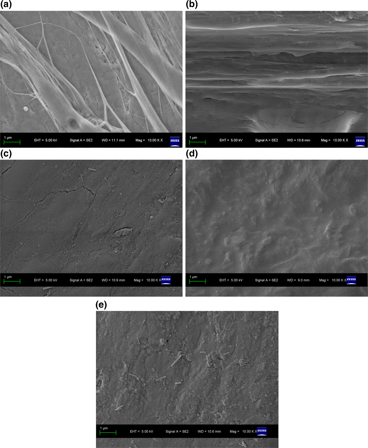
Fig. 9. SEM images of the worn surfaces of PTFE and HNT/PTFE nanocomposites: (a) PTFE; (b) pristine HNTs; (c) HNT-SDS; (d) HNT-PMMA; (e) HNT-COOH.
In the case of the wear debris formed during the sliding test of the composite that shows a low specific wear rate, long and narrow ribbons or short and wide ribbons are observed (Fig. 10). However, without reinforcement, PTFE may also form very large lump- or plate-like wear debris (Fig. 10a). The introduction of the modified HNTs produced smaller amounts of wear debris compared with pure PTFE. It is highly probable that these smaller amounts of debris stay longer at the contact region during the friction process. Some smaller debris particles and very fine modified HNTs might even reside in roughness valleys (Wang et al., Reference Wang and Yan2006). Moreover, the small size of the wear debris produced by the nanocomposites demonstrates the role of the filler in impeding large-scale fragmentation. This result supports the interpretation regarding improvement of the wear resistance of PTFE by reducing the size of wear debris.
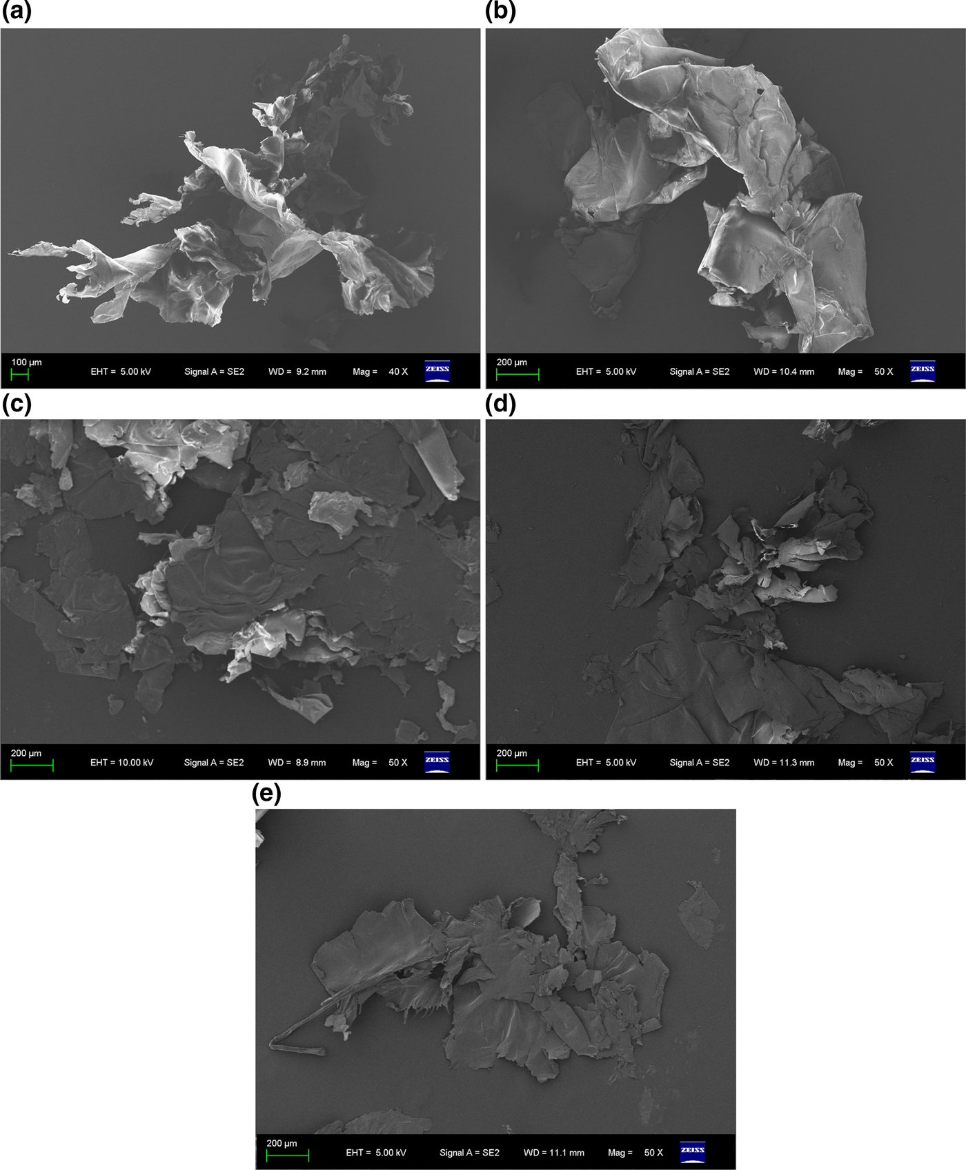
Fig. 10. SEM images of wear debris of PTFE and HNT/PTFE nanocomposites: (a) PTFE; (b) pristine HNTs; (c) HNT-SDS; (d) HNT-PMMA; (e) HNT-COOH.
CONCLUSIONS
Three types of modifiers were used to improve the dispersion of HNTs in the PTFE matrix and the modified HNTs were characterized by various methods. The mechanical properties of the modified HNT/PTFE nanocomposites improved relative to pure PTFE, and this in turn improved the workability of PTFE. The tribological behaviour of PTFE nanocomposites filled with pristine and modified HNTs was investigated. Due to the large-scale fragmentation of the PTFE, addition of the modified HNTs to PTFE caused remarkable increases in wear resistance relative to pure PTFE and the pristine HNT-filled PTFE nanocomposite of 21–82 and 9–40 times, respectively. These results indicate that modified HNTs applied as fillers in reinforced PTFE could play a significant role in replacing expensive nano-fillers.
ACKNOWLEDGEMENTS
This work was supported by the Talent Introduction Fund of Yangzhou University (2012), the Zhenjiang High Technology Research Institute of Yangzhou University (2017), the Key Research Project – Industry Foresight and General Key Technology of Yangzhou (YZ2015020), the Innovative Talent Program of Green Yang Golden Phoenix (yzlyjfjh2015CX073), the Yangzhou Social Development Project (YZ2016072), the Jiangsu Province Six Talent Peaks Project (2014-XCL-013) and the Jiangsu Industrial–Academic–Research Prospective Joint Project (BY2016069-02). The authors also acknowledge the Project Funded by the Priority Academic Program Development of Jiangsu Higher Education Institutions. The data in this paper originated from the Test Center of Yangzhou University.


