


1. INTRODUCTION
The Global Positioning System (GPS) has been widely used for estimating coseismic displacement with accuracies ranging from a few centimetres to a few millimetres, in support of both the modelling of fault rupture and investigations of mechanical fault behaviour (Larson, Reference Larson2009). At the same time, however, the limitation of high-rate GPS is widely recognised; its high precision can only be guaranteed for the displacement information, whereas the velocity and acceleration information usually involves large uncertainties caused by environmental and instrumental noises (Elósegui et al., Reference Elósegui, Davis, Oberlander, Baena and Ekström2006). On the other hand, a digital accelerometer can measure strong ground motion with a much higher resolution than the GPS, but its records are often plagued by what we call baseline shifts (acceleration bias): small steps or distortions in the reference level of motion (Iwan et al., Reference Iwan, Moser and Peng1985). In this study, the baseline (zero acceleration) is only related to the accelerometer records, which means it is different from the traditional GPS baseline (relative distance). The baseline shifts of the accelerometer are caused by the tilting and/or rotation of the accelerometer itself in the coseismic period, and they will lead to an integrated velocity and/or displacement with large uncertainties. In previous studies, the baseline shifts of the accelerometer are mainly corrected by empirical methods (Wang et al., Reference Wang, Schurr, Milkereit, Shao and Jin2011). A challenging issue of these previous methods is the empirical criterion needed to determine the two timing parameters (the beginning and end of the transient baseline shifts) of the bi-linear correction. As the baseline shifts can happen at any time, especially in the coseismic period, different timing windows may involve large and unquantifiable uncertainties compared with the geodetic results (Wang et al., Reference Wang, Parolai, Ge, Jin, Walter and Zschau2013). There are some published approaches for an integrated processing of high-rate GPS and accelerometer records. Bock et al. (Reference Bock, Melgar and Crowell2011) presented a methodology to optimally estimate the displacement in near real-time from a combination of the GPS relative positioning displacements and raw accelerometer acceleration records by a Kalman filter. This may avoid problematic baseline shifts to some extent. However, it is still difficult to constrain the baseline shifts, as these baseline shifts cannot be absorbed completely by the dynamic noises of the filter, so the recovered results may have a large offset. In Wang et al. (Reference Wang, Parolai, Ge, Jin, Walter and Zschau2013), a trigonometric function polynomial was formed to express the baseline shifts, and a least-squares solution was used to determine the baseline shifts by making the corrected displacements optimally consistent with the high-rate GPS displacement. Their approach can retrieve high-precision velocity and displacement to some extent, but the assumptions of the trigonometric function polynomial are influenced by subjective factors since the baseline shifts are very complex, and the method cannot be operated in real-time. Tu et al. (Reference Tu, Wang, Ge, Walter, Ramatschi, Milkereit, Bindi and Dahm2013) presented a cost effective approach to retrieve high precision and broadband ground motion information by joint use of a single-frequency GPS and a MEMS accelerometer, and validated it by an experimental dataset. Li et al. (Reference Li, Ge, Zhang, Wang, Klotz and Wicket2013) used accelerometer data after applying baseline shift corrections to strengthen GPS solutions for better integer ambiguity-fixing and consequently better accuracy. Geng et al. (Reference Geng, Bock, Melgar, Crowell and Haase2013a) proposed that a small bias of the acceleration can be modelled as a random walk process to be estimated together with displacement, but they did not study the bias in depth as there are no significant baseline shifts observed for a minor earthquake. In Tu et al. (Reference Tu., Ge, Wang and Walter2014), the baseline shifts in strong-motion records are firstly estimated by GPS measurement, then corrected to recover the coseismic waves in a short period. The high-frequency acceleration records from the strong motion are not fully used to improve the GPS results. Tu and Wang (Reference Tu and Wang2014), mainly discussed the idea that with an integrated Kalman filter and multi-sensors, the coseismic waves can be optimally recovered, especially when the observation conditions are very bad.
In this study, we propose an approach of tight integration with GPS and accelerometer records to complement each others' advantages. Our approach is designed not only to automatically correct the transient baseline shifts, but also to improve the PPP convergence and precision, and can provide real-time high-precision ground motion information. After an introduction of the theoretical and technical background, the new approach was employed to analyse the experimental data which was recorded by collocated GPS and accelerometer. Some conclusions and discussions are provided at the end.
2. METHODOLOGY
Precise Point Positioning (PPP) achieves a precision of a few centimetres or millimetres after convergence (Zumberge et al., Reference Zumberge, Heflin, Jefferson and Watkins1997). Meanwhile the precision and convergence speed can be improved by integer ambiguity-fixing (Ge et al., Reference Ge, Gendt, Rothacher, Shi and Liu2008; Geng et al., Reference Geng, Meng, Dodson, Ge and Teferle2010; Reference Geng, Teferle, Meng and Dodson2011). Moreover, it operates with a single station, there is no need for reference stations and simultaneous observation; it is low-cost and convenient compared with relative positioning and GPS Real Time Kinematic (RTK). So it is possible to detect the baseline shifts of the accelerometer for a collocated pair of one GPS receiver and one accelerometer by PPP. The main idea is that the displacement retrieved by the high-rate (several Hz) PPP only contains a small random error after all the observation errors are accurately corrected. The accelerometer observations have a much higher resolution (80–200 Hz), but the velocity and displacement waves are easily contaminated by the baseline shifts. Fortunately, the advantages of each method can be complementary when integrating the two measurements. The combined results will be more robust since the system errors are corrected and the random errors are weakened. In this approach, the acceleration records of the accelerometer are integrated into the PPP model, the baseline shifts of the accelerometer are estimated as unknown parameters together with the coordinates, troposphere, clock error and ambiguities. The Kalman filter is used for parameter estimation, meanwhile the Helmert method of variance components estimation is used to adjust the random model (Cui et al., Reference Cui, Yu, Tao, Liu, Yu, Sun and Wang2001). Four time series in the form of displacement, velocity, acceleration and baseline shifts are obtained in real time by the combined system.
Briefly, the observations of the combined systems are classified into three categories, carrier phase, pseudorange and acceleration. Then, the observation equations are written as follows:
 $$l_l = A \cdot s + B \cdot z + c \cdot t + \lambda \cdot N + \varepsilon _l, \; \varepsilon _l {\rm \sim} N{\rm (0,}\, q_l {\rm )}$$
 $$l_p = A \cdot s + B \cdot z + c \cdot t + \varepsilon _p, \; \varepsilon _p {\rm \sim} N{\rm (0,} \, q_p {\rm )}$$
 $$l_a = a + u + \varepsilon _a, \; \varepsilon _a \sim N(0,{\rm} q_{a_0} )$$
where the symbols l l and l p denote the GPS carrier phase and pseudorange observation. l a denotes the acceleration observation by the accelerometer, A and B are the designed matrix for receiver position and tropospheric delay. λ is the wavelength, and c is the speed of light. s, a and u denote the receiver position, acceleration and baseline shifts corrections of the accelerometer. z, t and N are the tropospheric zenith delay, receiver clock and phase ambiguity. ε l, εp and ε a are the measurement noises of the carrier phase, pseudorange and acceleration observations, their variances are q l, qp and  $q_{a_0} $ respectively.
Equations (1) to (3) can be rewritten as:
 $$y_k = M_k \cdot x_k + \varepsilon _{y_{k}}, \quad \varepsilon _{y_k} \sim N(0,{\rm} Q_{y_{k}} )$$
 $$y_k = \left[ {\matrix{ {l_l} \cr {l_p} \cr {l_a} \cr}} \right]$$
 $$M_k = \left[ {\matrix{ A & 0 & 0 & 0 & B & {\rm c} & \lambda \cr A & 0 & 0 & 0 & B & {\rm c} & 0 \cr 0 & 0 & 1 & 1 & 0 & 0 & 0 \cr}} \right]$$
 $$x_k = \left[ {\matrix{ {s_k} & {v_k} & {a_k} & {u_k} & {z_k} & {t_k} & {N_k} \cr}} \right]^T $$
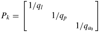 $$P_k = \left[ {\matrix{ {1/q_l} & {} & {} \cr {} & {1/q_p} & {} \cr {} & {} & {1/q_{a_0}} \cr}} \right]$$
where y k is the observation vector, x k is the estimated parameters vector, M k is the coefficient matrix, P k and  $Q_{y_k} $ are the weight matrix and noise variance matrix,
  $\varepsilon _{y_{_k}} $ is the noise, v k denotes the vector of the receiver velocity, k is the epoch index.
Usually, the dynamic state equation of the acceleration can be given as:
 $$a_k = a_{k{\rm -} 1} + q_a $$
where q a is the dynamic state noise of the acceleration. As the acceleration is very sensitive, a small bias will lead to an integrated velocity and displacement with a large offset. Meanwhile, the change of acceleration is very swift during the coseismic period; it is difficult to determine the optimal dynamic state noise q a of the acceleration to control the state transformation while using the traditional acceleration state Equation (9). In this approach, the acceleration and baseline shifts are treated as a random walk process, a transformation is made such that the baseline shifts' corrected acceleration a k−1′ is used instead of the estimated acceleration a k−1 in the state equations, thus:
 $$a_k = (l_{a(k)} - u_{k{\rm -} 1} ) + q_{au} $$
 $$a_{k - 1} ' = (l_{a(k)} - u_{k{\rm -} 1} )$$
 $$q_{au} = q_u + q_{a0} $$
Here q au is the new dynamic state noise of the acceleration, it contains the dynamic state noise q u of the baseline shift and the observation noise q a0 of the acceleration. Hence, the new dynamic state noise q au is used instead of q a for the acceleration. As the observation of the acceleration with a small noise, the main part of q au is the dynamic state noise q u of the baseline shift, its variation is smaller than the acceleration and easy to control (Tu et al., Reference Tu., Ge, Wang and Walter2014).
Then, by the improved state Equation (10a), the state equations of the combined system can be given as follows:
 $$x_k = {\rm \Phi} _k \cdot x_{k{\rm -} 1} + \varphi _k \cdot l_{a(k)} + \varepsilon _{s_{_k}}, \ \varepsilon _{s_k} {\rm \sim} N{\rm (0,} Q_{s_{_k}} {\rm )}$$
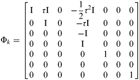 $${\rm \Phi} _k = \left[ {\matrix{ {\rm I} & {\tau {\rm I}} & 0 & {{\rm -} \displaystyle{1 \over 2}\tau ^2 {\rm I}} & 0 & 0 & 0 \cr 0 & {\rm I} & 0 & {{\rm -} \tau {\rm I}} & 0 & 0 & 0 \cr 0 & 0 & 0 & {\rm -I} & 0 & 0 & 0 \cr 0 & 0 & 0 & {\rm I} & 0 & 0 & 0 \cr 0 & 0 & 0 & 0 & 1 & 0 & 0 \cr 0 & 0 & 0 & 0 & 0 & 0 & 0 \cr 0 & 0 & 0 & 0 & 0 & 0 & 1 \cr}} \right]$$
 $$\varphi _k = \left[ {\matrix{ {\displaystyle{{\tau ^2} \over 2}{\rm I}} \cr {\tau {\rm I}} \cr {\rm I} \cr 0 \cr 0 \cr 0 \cr 0 \cr}} \right]$$
 $$Q_{s_k} = \left[ {\matrix{ {\displaystyle{{\tau ^4} \over {20}}{\rm I}q_u} & {\displaystyle{{\tau ^3} \over 8}{\rm I}q_u} & 0 & {\displaystyle{{\tau ^2} \over 6}{\rm I}q_u} & 0 & 0 & 0 \cr {\displaystyle{{\tau ^3} \over 8}{\rm I}q_u} & {\displaystyle{{\tau ^2} \over 3}{\rm I}q_u} & 0 & {\displaystyle{\tau \over 2}{\rm I}q_u} & 0 & 0 & 0 \cr 0 & 0 & {\tau {\rm I}q_{au}} & 0 & 0 & 0 & 0 \cr {\displaystyle{{\tau ^2} \over 6}{\rm I}q_u} & {\displaystyle{\tau \over 2}{\rm I}q_u} & 0 & {{\rm I}q_u} & 0 & 0 & 0 \cr 0 & 0 & 0 & 0 & {\tau q_z} & 0 & 0 \cr 0 & 0 & 0 & 0 & 0 & {\tau q_t} & 0 \cr 0 & 0 & 0 & 0 & 0 & 0 & 0 \cr}} \right]$$
where Φ k is the dynamics transition matrix. It is emphasised that the third element (acceleration) is zero, because for the state transition, the baseline shift corrected acceleration Equation (10a) is introduced instead of the estimated acceleration Equation (9) at the last epoch. Symbol φ k is the acceleration input matrix,  $Q_{s_{_k}} $ is the dynamic noise variance matrix, τ is the accelerometer sample interval, I is a 3×3 identity matrix, q z and q t are the dynamic noise variances for the tropospheric zenith wet delay and receiver clock respectively.
With the combined observational Equations (4) and state Equation (11), a Kalman filter can be employed to estimate the unknown parameters; it contains two steps of prediction and filter (Yang et al., Reference Yang, He and Xu2001).
Step one: prediction (a priori estimation)
 $$\overline {x_k} = {\rm \Phi} _k \cdot \mathop {x\hskip-2{\rm\hat}\hskip2\limits_{k-1}} + \varphi _k \cdot l_{a(k)} $$
 $$\overline {Q_k} = {\rm \Phi} _k \cdot Q_{k - 1} \cdot {\rm \Phi} _k ^T + Q_{s_{k - 1}} $$
Step two: filter (a posteriori estimation)
 $$Q_{y_k} = P^{ - 1} + M_k \cdot \overline Q _k \cdot M_k ^T $$
 $$Q_k = (\overline {Q_k} ^{ - 1} + M_k ^T \cdot Q_{y_k} ^{ - 1} \cdot M_k )^{ - 1} $$
 $$\mathop {x\limits\hskip-2{\rm\hat}\hskip2_k} = \overline {x_k} + Q_k \cdot M_k ^T \cdot Q_{y_k} ^{ - 1} \cdot (y_k - M_k \cdot \overline {x_k} )$$
where Q k is the variance of the filter system, symbol − represents the prediction values, symbol ^ represents the filter values. The initial values of Q 0 are given by the experience values, two entries of X 0, namely initial coordinates and receiver clock, are determined by code-based positioning, the other entries are assigned as zero. It is emphasised that in this study, the acceleration vector is independent of other state vectors (displacement, velocity), the correlations between acceleration state vector and the current epoch's accelerometer observations are not taken into account; we only consider their correlation in the observation equations, so the customary procedures of the Kalman filter can be applied.
The GPS sampling frequencies (several Hz) are traditionally lower than the accelerometer sampling frequencies (80–200 Hz), thus the formulation needs to be adapted to this multi-rate environment (Smyth and Wu, Reference Smyth and Wu2006) by performing the prediction stage in Equations (15) and (16) at every time-step and applying the filter update stage in Equations (17) to (19) only when a GPS sample becomes available.
The random model is usually determined as follows (Bock et al., Reference Bock, Melgar and Crowell2011; Xu et al., Reference Xu, Shi, Fang, Liu, Niu, Zhang and Yanagidani2012):
 $$p_l = 1/q_l = \left( {\matrix{ {1/q_{l_0}} & {\theta \geqslant 30 \deg} \cr {1/(q_{l_0} \cdot 2\sin \theta )} & {\theta \lt 30 \deg} \cr}} \right)$$
 $$p_p = 1/q_p = \left( {\matrix{ {1/q_{p_0}} & {\theta \geqslant 30 \deg} \cr {1/(q_{p_0} \cdot 2\sin \theta )} & {\theta \lt 30 \deg} \cr}} \right)$$
 $$p_a = 1/q_{a_0} $$
where  $q_{l_0} $,
  $q_{\,p_{_0}} $ and
  $q_{a_0} $ are the observation noise variance of the phase, pseudorange and acceleration observation, θ is the satellite elevation angle. Generally, the empirical weights are not optimal for different types of observations, which means their unit weight variances are not equal. We can use the Helmert method of variance components estimation to adjust the random model (Cui et al., Reference Cui, Yu, Tao, Liu, Yu, Sun and Wang2001).
Firstly, the observations of the combined system are divided into phase, pseudorange and acceleration, the empirical weight as in Equation (20) is used for the filter estimation. The variance of the unit weight is computed by using the simplified Helmert formula for each kind of observations, such that:
 $$v_k = M_k \cdot \mathop {x\limits\hskip-2{\rm\hat}\hskip2_k} \limits - y_k, \quad \delta _{0_i} ^2 = \displaystyle{{V_i^T P_i V_i} \over {n_i}} $$
here v k is the observation residuals at epoch k for all the observations (contain three types of observations); V i is the observation residuals for each type of observation (only phase or only pseudorange or only acceleration observations); P i is the empirical weight for each kind of observation; n i is the numbers for each kind of observation;  $\delta _{{\rm 0}_i} ^2 $ is the variance of the unit weight for each kind of observation, i represents the type of observation.
Secondly, determine the new weights for each type of observation,
 $$\mathop {{P\hskip-2{\rm\hat}\hskip2}_i} \limits = \displaystyle{C \over {\mathop {{\delta\hskip-1{\rm\hat}\hskip2} _{0_i} ^2} \limits P_i^{ - 1}}} $$
where C is a constant, its value can be determined by one of the variance of the unit weight.
Thirdly, iterate for steps one and two until all the variance of the unit weight is equal or approximately equal, then update for the next epoch. While using the a posteriori estimation, the random model of the combined system is more objective and the filter results are more robust. On one side, if there is no earthquake event, the high-rate acceleration observations of the accelerometer will give a strong constraint on the station state vector, leading to a significant improvement in both convergence time and position accuracy. On the other side, the high precision GPS will contribute by recognising and correcting the accelerometer's baseline shifts when the earthquake occurs.
3. EXPERIMENTAL ANALYSIS
Figure 1 shows the platform that we used in the experiment carried out in December 2012. The platform, which can slide along a table, includes a dynamic GPS antenna (Type: JAV_RINGANT_G3T NONE), a low-cost MEMS-type accelerometer (Fleming et al., Reference Fleming, Picozzi, Milkereit, Kuehnlenz, Lichtblau, Fischer, Zulfikar and Ozel2009) and a high-precision accelerometer (CMG-5 T Compact made by Guralp Systems Ltd). The sampling rate is 50 Hz for the GPS and 100 Hz for the accelerometer. The maximum sliding distance of the platform is restricted to about 0·5 m. As the ultra-high-rate GPS has much larger noise, the GPS data is decimated to 5 Hz for the data analysis. Precise ephemeris and other positioning products are provided by the International GNSS Service (IGS), and the data is processed in a simulated real-time mode. We simulated eight experiments by moving the platform from one side to the other, the reference displacements are recorded by the vernier calliper which is fixed on the table. For each experiment, we initially kept the rig static at the start point for about five minutes; secondly, we slid the combined instruments from the start point to the end point over about one minute; thirdly, the rig was kept static at the end point for about five minutes; finally, the rig was returned to the start point for the next experiment. For the eighth experiment, it was not returned to the start point, as this was the end of the experiment. In addition, we only analysed the data recorded by the MEMS sensor (SM1), as the data recorded by the Guralp sensor (SM2) is little better than the MEMS sensor and had no substantial difference for the retrieved results, but as this sensor is more expensive than MEMS sensors, they are not commonly used.

Figure 1. The experiment platform consisting of a GPS receiver, a low-cost accelerometer of the MEMS type (SM1) and a high-precision accelerometer of the Guralp type (SM2).
Figure 2 shows the acceleration, velocity and displacement of all experiments. Figure 2(a) shows the raw acceleration records (black) and the estimated baseline shift corrections (red). Due to the reasons of instrument instalment and environmental variations, the raw acceleration has a large initial baseline shift (about 1·17 m/s2). Meanwhile, these baseline shifts changed following the ground motion. Figures 2(b) and 2(c) are the time series of the corrected acceleration and velocity. We can see that the values are around zero when there is no movement. Figure 2(d) shows the time series of the corrected displacement. The details of each simulation will be discussed below.
Figure 2. The results of the experiment. (a) The raw acceleration records (black) and the estimated baseline shifts (red), (b) The corrected acceleration, (c) The corrected velocity, (d) The corrected displacement. The symbol “Ti” represents the number of the experiment.
Figure 3 shows the details of the first experiment. Though the velocity and acceleration by the GPS-only system are very noisy, the displacement reflects the reality with an uncertainty of a few centimetres (in Figure 3(a)). In contrast, the accelerometer-based acceleration has a much higher signal-to-noise ratio, but the integrated velocity and displacement have a larger offset than that of the GPS (in Figure 3(b)). While for the combination of the two measurements, not only the velocity and acceleration are recovered, but also the displacement with much smaller noise (in Figure 3(c)). Meanwhile, the baseline shift corrections are compared in Figures 3(d) and (e) between the empirical method of Wang et al. (Reference Wang, Schurr, Milkereit, Shao and Jin2011) and the new approach. For the empirical methods, the baseline shift correction of the acceleration is divided into three parts, the pre-event, transient part and post-event according to the characteristics of the acceleration, and corrected the integrated velocity with a continuous double broken line (Wang et al., Reference Wang, Schurr, Milkereit, Shao and Jin2011), this is shown in Figure 3(d). This means that the baseline shifts of the acceleration are treated as a constant in the coseismic period, but the tilting and/or rotation of the instrument is not a simple event since the ground is shaking during the whole coseismic period, the baseline shifts are changing all the time, these empirical methods are not objective and have large uncertainties. For the new approach, the baseline shifts of the acceleration are estimated and corrected as continuous unknown parameters, shown in Figure 3(e). It is less subjective and more accurate to describe the baseline shifts, so the combined system can obtain the optimal displacement, velocity and acceleration information, as shown in Figure 3(c).
Figure 3. The example of the first experiment. (a), (b), (c) are the results retrieved by GPS, accelerometer and the combined system, from left to right are the time series of displacement, velocity and acceleration respectively; (d) is the velocity correction line by the empirical method of Wang et al. (Reference Wang, Schurr, Milkereit, Shao and Jin2011), (e) is the acceleration correction line by the new approach; the red line marks the displacement reference value.
In Figure 4, we summarise the results from the tight integration data processing for all the other seven experiments. As expected, the baseline shifts of the accelerations are recognised and corrected; the post-seismic velocity varies approximately around zero, while the displacement converges to the reference values. The Root Mean Square (RMS) deviation between the recovered and reference displacements is below 2·0 cm. As in the experiment, the platform is fixed on the ground, and the baseline shifts are mainly caused by the tilting of the platform. As proposed by Geng et al. (Reference Geng, Melgar, Bock, Pantoli and Restrepo2013b), these tilts can be estimated from collocated high-rate GPS and accelerometers, they are physical quantities and meaningful to rotational seismology. By analysis of the recognised baseline shifts, we may find that they have nearly the same variation tendency with the movements. Before the slip, there are only stable initial baseline shifts. When the instruments begin to slip, the transient baseline shifts emerge and change following the movements; the post-seismic baseline shifts are also stable after the slip. In experiments six and seven, the permanent displacements are zero, so the baseline shifts are nearly the same between the post-seismic and pre-seismic periods. Though the baseline shifts are very complex in the coseismic period, we also find that they have strong correlations with the ground motion, so the empirical methods of double broken line correction are neither objective nor accurate. These experimental results have shown that the tight integration of the two measurements are able to recognise and correct the accelerometer's baseline shifts, meanwhile, high precision of ground motion information can be obtained in real-time.
Figure 4. Results from all other seven experiments. From left to right are the time series of estimated baseline shifts, velocity and displacement respectively. From top to bottom are the experiments from two to eight respectively. The red lines mark the displacement reference values, symbol “Ti” represents the number of the experiment.
Figures 5(a) and (b) show the comparison of the PPP's convergence. It can be seen that the PPP convergence speed is improved after the integration of the GPS and accelerometer records, especially in the east-west (red line) and vertical (blue line) components. Meanwhile, the STD of the noise are reduced from (0·019, 0·012, 0·032) m to (0·003, 0·004, 0·008) m in ENU components respectively. In Figure 5(c), the zenith wet delay of the tropospheric shows nearly no convergence process for the combined system, and it is more stable; the STD of the noise is improved from 0·005 m to 0·001 m. Hence, the high resolution acceleration also contributes to the PPP solution.
Figure 5. The comparison of the PPP convergence speed and tropospheric zenith wet delay. (a) Left: the PPP convergence process by GPS-only data; (b) Middle: the PPP convergence process by the integration of GPS and accelerometer data; (c) Right: the comparison of the tropospheric zenith wet delay.
4. CONCLUSIONS AND DISCUSSIONS
We have proposed a new approach of tight integration process of collocated high-rate GPS and accelerometer measurements and validated it by several experiments. The acceleration records collected from the accelerometer are integrated into the PPP solution model, meanwhile, the baseline shifts are estimated as unknown parameters like coordinates and ambiguities, the Kalman filter is employed for the real-time solution and the a posteriori estimation is used to adjust the random model. The experimental results show that the tightly integrated system can complement the advantages of each component completely. For the accelerometer, the baseline shifts are estimated and corrected, high-precision velocity and displacement are recovered. As the baseline shifts are not always present, it is best to firstly detect whether the baseline shifts have happened and how significant they are and then adaptively estimate and correct them. The transient baseline shifts are very small, of the order of maybe 10–3 m/s2 to 10–5 m/s2 and it is very difficult to detect them precisely. Moreover, the baseline shifts are mostly caused by the instrument tilts. Recovering coseismic point ground tilts from collocated GPS and accelerometers is more meaningful to rotational seismology (Geng et al., Reference Geng, Melgar, Bock, Pantoli and Restrepo2013(b)). For the GPS, the PPP convergence speed and precision are improved. For the combined system, four time series in the form of displacement, velocity, acceleration and baseline errors are obtained in real-time with high precision.
In comparison with the previous integration methods, which are mostly used for a loose integration of the two measurement systems in the post-processing domain, the present method can be used for a real-time integration in the raw observation domain. In addition, comparison with the empirical baseline shift correction methods, which use the empirical double broken line to correct the velocity, the present method estimated and corrected the transient baseline shifts of the accelerations in real-time, and is more objective and accurate. The test results have shown that by using the integrated data processing technology, it preserves the best and avoids the worst characteristics of each sensor, real-time and broadband ground motion information can be provided reliably, which has an important impact in earthquake monitoring and provision of early warning.
ACKNOWLEDGMENTS
We thank our colleagues for their technical supports in the experiment. Mr. Rui Tu and Mr. Kejie Chen are supported by the China Scholarship Council for their Ph. D. study in Germany.

