I. INTRODUCTION
Nowadays, the Wireless Local Area Networks (WLANs) are widely used throughout the world. The trend for WLAN products is growing rapidly with the roll out of IEEE 802.11b products into the public, home, and office environments. With the rapid growth in consumer demand for wireless multimedia, the demand for higher throughput and spectral efficiencies is also increased. The three popular frequency bands specified by IEEE 802.11a are 5.15–5.25, 5.25–5.35, and 5.725–5.825 GHz. Similarly, HIPERLAN/2 specifies the bands from 5.15–5.35 and 5.470–5.725 GHz.
The IEEE 802.11a system-specified bands are widely used in the USA and in many countries the 5.47–5.825 GHz band is widely used. Similarly, in Europe the unlicensed 5.4 GHz band gained many applications such as WLAN, HIPERLAN, Radio Local Area Networks (RLAN), Fixed Wireless Access Systems (FWA), etc. Microstrip antennas are suitable for such applications due to their low-cost, low-profile, lightweight, and ease of fabrication. However, the main disadvantage of these antennas is their narrow bandwidth. In the literature, many techniques are discussed to improve the bandwidth of microstrip antennas. The reduction of ground plane to improve the impedance bandwidth of these microstrip antennas is discussed in [Reference Bao and Ammann1, Reference Azim, Islam, Misran, Cheung and Yamada2].
In the current advanced wireless scenario, multiple-input–multiple-output (MIMO) technology plays a major role in achieving larger data rates and improved spectral efficiencies. The MIMO technique for improving the channel capacity by employing multiple antennas at the transmitter and receiver side was first proposed by Foschini and Gans [Reference Foschini and Gans3]. However, when the antennas are placed at closer spacing in the MIMO devices, mutual coupling comes into existence deteriorating the performance of the overall system. The origin of the mutual coupling between two identical antennas is studied in [Reference Nikolic, Djordevic and Nehorai4] and its impact on the capacity of MIMO systems is analyzed in [Reference Abouda and Haggman5].
Many researchers have developed various techniques to minimize the mutual coupling between the elements of antenna arrays. Surface current distribution plays key role in deciding the amount of mutual coupling between the antennas. A MIMO system with reduced mutual coupling is developed in [Reference Chou, Cheng, Hsu and Kuo6], by altering the ground surface current distribution. Employing EBG structures on the ground plane also reduces mutual coupling as discussed in [Reference Caminita7]. The method of using defective ground structures (DGS) to improve isolation is another technique as discussed in [Reference Constantine and Constantinou8, Reference Ahmed-Ibrahim, Mahmoud-Abdalla, Adel Abdel-Rahman and Hesham9]. In [Reference Dossche, Blanch and Romeu10], considerable amount of isolation was achieved using a two-port network, which comprises matching network and decoupling network. In [Reference Addaci11], the authors achieved good isolation characteristics in both lower and upper bands by employing slots on the metalized substrate.
To support the higher spectral efficiencies of the current wireless devices, the antenna systems are to be developed with wideband characteristics and reduced mutual coupling. Most of the research on MIMO antenna design is concentrated either to enhance the impedance bandwidth or to improve the isolation between antennas, and a small amount of work exists in the current literature to address both the problems simultaneously. Hence in the present work, a novel antenna system giving both improved bandwidth and isolation simultaneously is proposed. The developed MIMO antenna system gives an impedance bandwidth of 38% in the frequency range 5–7.3 GHz, resonating at a dual-band of 5.4 GHz to meet the requirements of current WLAN/HIPERLAN applications and at 6.8 GHz, making it suitable for many wireless applications such as Location Tacking Applications for Emergency Services (LAES) as specified by Electronics Communications Committee (ECC) At 5.4 GHz resonant frequency, the proposed system gives a reduced mutual coupling of −27 and −19 dB at 6.8 GHz resonant frequency and in the entire band the coupling is maintained well below −16 dB. These characteristics are achieved on a reduced ground plane FR4 substrate of thickness 1.56 mm. The obtained bandwidth is considerably high for such a low-profile antenna and is better compared with the bandwidth of the antenna discussed in [Reference Yikai, Shiwen and Zaiping12]. All the simulations are carried out using CST simulator. The simulated and measured results are found in good agreement.
II. ANTENNA DESIGN
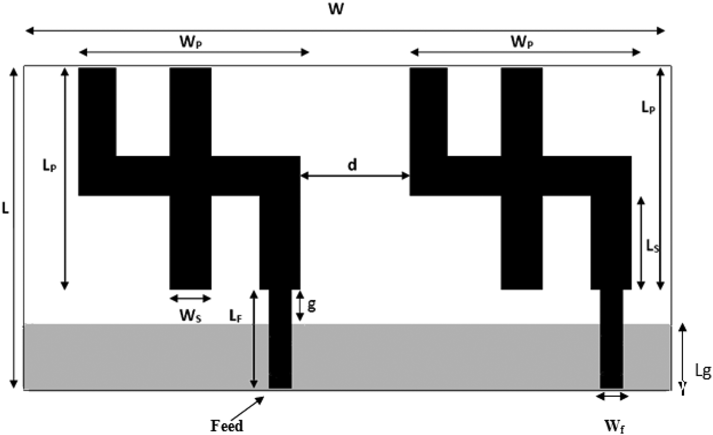
The geometry of the proposed MIMO antenna system is shown in Fig. 1. The antenna is a printed monopole antenna with reduced ground plane. The area of single antenna is 36 × 54 mm2 and the total area of the MIMO system is 110 × 54 mm2. Both the antennas in the MIMO system are separated with a distance of d = 18 mm (0.32 λ 0 at 5.4 GHz and 0.4 λ 0 at 6.8 GHz). The antennas are fed with microstrip feed with a separation of 55 mm between the two feeds. The feed is given to the rectangular strip of width W f = 3 mm as shown in Fig. 1. The dimensions of the designed antenna are mentioned in Table 1.

Fig. 1. The proposed MIMO antenna system.
Table 1. Dimensions of the proposed MIMO system.

The bandwidth of a microstrip antenna can be enhanced by reducing the ground or by employing slots on the ground plane [Reference Azim, Islam, Misran, Cheung and Yamada2]. In the present work, the enhancement of bandwidth is achieved by reducing the ground plane. A gap analysis is performed by changing the dimension of ground length L g as shown in Fig. 2, for obtaining improved bandwidth with good return loss. The study shows that for L g = 15.6 mm, i.e. for the gap g = 2.4 mm, an improvement in bandwidth with good return loss is obtained at the desired resonant frequencies. Hence, the ground plane area is selected as 110 × 15.6 mm2 and with these dimensions the antenna is fabricated. The MIMO antenna array is printed on an FR4 substrate of permittivity ε r = 4.4 having a thickness of h = 1.56 mm.

Fig. 2. Simulated return loss for various values of L g.
To understand the design trade-offs and physical insight of the proposed MIMO antenna structure, the parametric analyses are performed. The important parameters affecting the antenna resonant behavior are identified as W p, L p and W s. The effect of W p and L p dimensions on S-parameters of the proposed design are shown in Fig. 3. From Figs 3(a) and 3(b), it can be observed that the desired resonant characteristics with good impedance bandwidth (38%) and a reduced mutual coupling of −27 dB at 5.4 GHz resonant frequency and −19 dB at 6.8 GHz resonant frequency are obtained for the dimensions W p × L p = 36 × 36 mm2. Another important parameter affecting the resonant behavior is W s and its effect on S parameters is shown in Fig. 4. From Figs 4(a) and 4(b), it can be observed that, W s mainly affects the resonant behavior of the antenna structure and slightly affecting the mutual coupling. The better value identified from the parametric analyses for W s is 9.6 mm. The photographs of the fabricated MIMO antenna structure are shown in Fig. 5.

Fig. 3. Parametric analyses w.r.t W p and L p. (a) Variation of S 11 parameters. (b) Variation of S 21 parameters.

Fig. 4. Parametric analyses w.r.t W s. (a) Variation of S 11 parameters. (b) Variation of S 21 parameters.

Fig. 5. Photographs of the fabricated MIMO array. (a) Top layer. (b) Bottom layer.
III. RESULTS AND DISCUSSION
The simulated and measured S 11 parameters of the developed MIMO antenna system are shown in Fig. 6. The developed antenna structure resonates at a dual-band of 5.4 and 6.8 GHz frequencies making it suitable for many wireless applications such as WLAN/HIPERLAN and LAES, respectively. The developed MIMO array is shown to give an impedance bandwidth of 38% over the frequency range 5–7.3 GHz, covering major part of the C-band (4–8 GHz). The bandwidth achieved in the present work is significant for such a low-profile antenna with a substrate thickness of 1.56 mm and ε r = 4.4. The most useful parameter to estimate the performance of a MIMO system is mutual coupling, which is shown in Fig. 7. The developed antenna structure gives a reduced mutual coupling of −27 dB at 5.4 GHz resonant frequency and −19 dB at 6.8 GHz resonant frequency and in the entire operating band the coupling is maintained well below −16 dB. The simulated and measured results are almost matching with a slight shift in the resonant frequency. This shift in the frequency is due to the fabrication tolerances at the feed point.

Fig. 6. Simulated and measured S 11 parameters of the proposed MIMO array.

Fig. 7. Simulated and measured results of mutual coupling between the two antennas.
The obtained isolation meets well the requirements of current wireless MIMO systems, where restriction in the spacing is the main criteria. The reason for the improvement in isolation and the basic idea behind arriving at the shape of the proposed antenna can be understood by analyzing the surface current distribution as shown in Fig. 8. The amount of mutual coupling between the two antennas in a MIMO system depends on the distance between two antennas and also on the directions of the current flowing on the surface of the antennas. If the current flows in same direction on the adjacent sides of both the antennas, the mutual coupling is more. Similarly, if the currents are in opposite direction, the induced mutual coupling is minimized [Reference Mak, Rowell and Murch13]. Owing to the unique structure of the proposed MIMO system, the surface currents flow in the opposite directions at the adjacent sides of both the antenna elements in the array (right part of the first antenna and left part of the second antenna), thus reducing the mutual coupling. The performance of the proposed work in terms of size of the antenna, mutual coupling, spacing between the elements and impedance bandwidth is compared with other existing work in the literature [Reference Rajo-Iglesias, Quevedo-Teruel and Inclán-Sánchez14–Reference Deukhyeon, Youngki, Taeho and Jaehoon16] as mentioned in Table 2. From the comparison, it can be concluded that the proposed antenna structure gives better performance in terms of both improved impedance bandwidth and isolation.

Fig. 8. Surface current distribution of the proposed MIMO antenna system.
Table 2. Comparison of the proposed antenna system with existing antennas in literature.

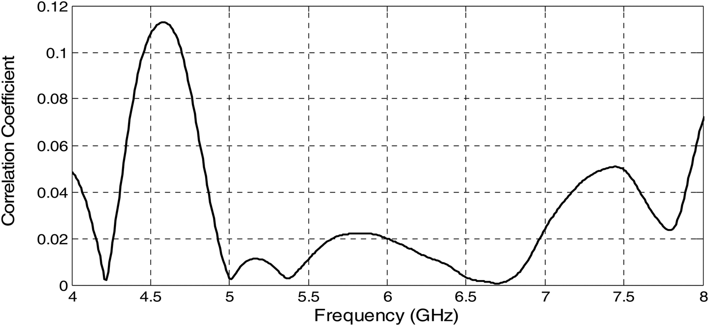
The performance of the proposed antenna is further evaluated with the help of another important parameter known as envelope correlation coefficient (ECC), which is defined using equation (1) [Reference Blanch, Romeu and Corbella17]. This parameter (ρ) is useful in estimating the diversity performance of a MIMO system. The ECC using the S parameters is calculated using equation (1) and plotted in Fig. 9. From the plot, it can be observed that the envelope correlation coefficient is very low in the operating frequency range, which indicates the good isolation between the two antennas in the MIMO system. The obtained ECC is <0.05 in the operating frequency band (5–7.3 GHz), and in [Reference Weiye, Wenbin and Guangli18, Reference Mohammad-Sharawi, Ahmed-Numan and Daniel-Aloi19], the ECC values are 0.15 and 0.3, respectively in the operating bands.

Fig. 9. ECC of the proposed two-element MIMO system.
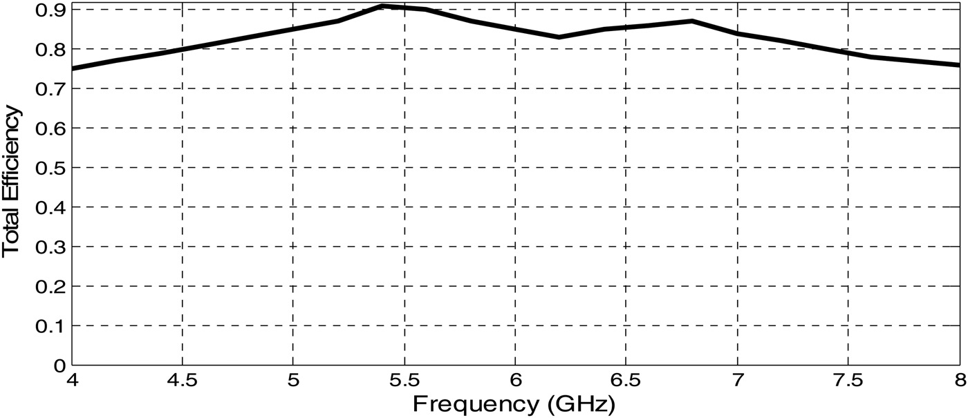
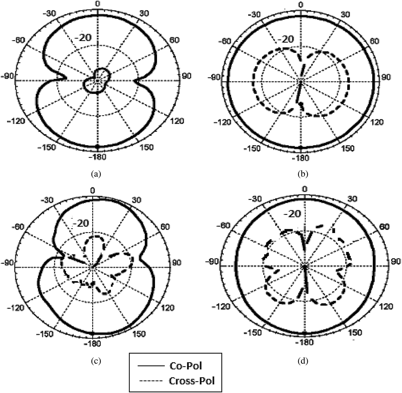
The latest works [Reference Addaci11, Reference Addaci, Diallo, Luxey, Le Thuc and Staraj20] in the existing literature focused on evaluating total efficiency (η tot) in addition to mutual coupling and ECC to further explore the behavior of MIMO antenna system performance. In the present work also, the simulated total efficiency is evaluated using equation (2) and is plotted in Fig. 10. (η rad represents the radiation efficiency taking the conducting and dielectric losses into account) The simulated total efficiency of the proposed MIMO antenna is shown in Fig. 10, from which it can be observed that the efficiency is more than 80% in the operating band. At the points of good return loss and isolation, the efficiency is found to be more, which is according to equation (2). The measured radiation patterns of the developed MIMO antenna system at 5.4 and 6.8 GHz frequencies are shown in Fig. 11. The co-polarization and cross-polarizations are well discriminated in E-plane compared with H-plane. In MIMO systems, the diversity gain is dependent on the cross-coupling in the antenna, indicating that the cross-polar discrimination (XPD) is indeed of importance for a well-functioning polarization diversity scheme.
 $$\rho=\displaystyle{{\left\vert {S_{11}^\ast S_{12}+S_{21}^\ast S_{22} } \right\vert ^2 } \over {\left({1 - \left\vert {S_{11} } \right\vert ^2 - \left\vert {S_{21} } \right\vert ^2 } \right)\left({1 - \left\vert {S_{22} } \right\vert ^2 - \left\vert {S_{12} } \right\vert ^2 } \right)}}\comma \;$$
Fig. 10. Simulated total efficiency of the proposed MIMO antenna system.

Fig. 11. Radiation patterns of the developed MIMO system: at 5.4 GHz for (a) E-plane, (b) H-plane; and at 6.8 GHz for (c) E-plane, (d) H-plane (solid line: co-pol; dashed line: cross-pol).
IV. CONCLUSIONS
In the present work, a two-element MIMO system with improved bandwidth and isolation is proposed and physically realized. As the current advanced wireless systems require the antenna systems with higher bandwidths and low mutual coupling at lower separations, the main objective of the present work is considered to achieve improved return loss characteristics, effective impedance bandwidth, and improved isolation characteristics. The proposed MIMO antenna array resonates at a dual-band of 5.4 and 6.8 GHz with an impedance bandwidth of 38% in the frequency range 5–7.3 GHz, with an isolation of 27 dB at 5.4 GHz resonant frequency and 19 dB at 6.8 GHz resonant frequency and maintaining a minimum isolation of 16 dB in the entire operating band. These characteristics are achieved without using any decoupling element and the developed system relatively simple to implement.
ACKNOWLEDGEMENTS
This work was supported by the Deanship of Scientific Research (DSR) at King Abdulaziz University, Jeddah, Saudi Arabia under grant no. 3-135-35-RG. We would like to acknowledge with thanks the DSR for the financial support.
 Mohammed Younus Talha was born in 1988. He received his B.Tech. degree in Electronics and Communications Engineering from Vazir Sultan College of Engineering, Khammam, India in 2010. He is currently working toward his M.Sc., degree in Electronics and Communication Engineering from Electrical and Computer Engineering Department at Faculty of EngineeringKing AbdulAziz University, Jeddah, Kingdom of Saudi Arabia. His research interests include the Design and Analysis of Microstrip Antennas and MIMO Systems.


