


I. INTRODUCTION
Over the last few decades, multipath effect was conceptualized negatively as it only causes signal fading in communication and introduces multipath ghosts in through-the-wall radar (TWR) target localization and imaging. However, in modern radar technology, multipath components can be exploited to aid in target detection, tracking, classification, and imaging with increased signal-to-clutter ratio at genuine target locations [Reference Setlur, Amin and Ahmad1–Reference Smith and Mobasseri9]. Multipath exploitation proved itself to be beneficial in through-the-wall sensing especially in non-line of sight scenarios where the received signal contains only multipath components. Though, according to [Reference Setlur, Alli and Nuzzo10, Reference Amin and Ahmad11], multipath exploitation in indoor localization has not been extensively studied yet.
In the literature, indoor targets are mainly localized using multipath exploitation with multi-antenna or synthetic aperture radar (SAR) systems [Reference Setlur, Amin and Ahmad1, Reference Setlur, Amin and Ahmad2, Reference Deiana, Kossen and Van Rossum4, Reference Smith and Mobasseri8, Reference Smith and Mobasseri9]. Recently, few contributions have been presented utilizing a single antenna instead [Reference Setlur, Smith, Ahmed and Amin3, Reference Muqaibel, Amin and Ahmad12]. Convincingly, localization with single antenna is more attractive as it enhances system flexibility and reduces the system cost greatly. With exception of [Reference Setlur, Smith, Ahmed and Amin3, Reference Muqaibel, Amin and Ahmad12] who used a single sensor, authors used multi-sensors or synthetic apertures with multipath exploitation to locate or track behind the wall targets.
Setlur et al.[Reference Setlur, Amin and Ahmad2] proposed a SAR-based system to associate and map multipath ghosts to their corresponding true target locations in indoor imaging. In [Reference Setlur, Amin and Ahmad1], the same authors utilized multipath exploitation to improve and maintain tracking of moving targets behind the walls. In the same year, authors in [Reference Deiana, Kossen and Van Rossum4] incorporated MIMO radar system to detect hidden targets while Smith et al. [Reference Smith and Mobasseri8] provided a method to localize multipath ghosts, which was then used in target classification using multiple antenna array.
Setlur et al. [Reference Setlur, Smith, Ahmed and Amin3] developed an algorithm using single sensor to localize the target taking extra information from the multipath returns. As an extension of [Reference Setlur, Smith, Ahmed and Amin3], in [Reference Muqaibel, Amin and Ahmad12] the authors proposed a single-antenna localization scheme, which exploits the embedded directivity in ultra-wideband (UWB) antennas [Reference Muqaibel, Amin and Ahmad12]. They considered first two arrivals and directivity of the antenna to reduce the number of possible target locations from 6 as in [Reference Setlur, Smith, Ahmed and Amin3] down to 4. The main challenge facing the scheme in [Reference Setlur, Smith, Ahmed and Amin3] is the complexity of the wall association algorithm to associate multipath returns with their respective walls. In our contribution, this challenge has been greatly reduced. In [Reference Muqaibel, Amin and Ahmad12], their method relies on correlation between the received and the set of possible signals, which are synthesized in priori which is avoided in our contribution.
This paper introduces an effective way of localizing an indoor target using single UWB antenna with the help of virtual radars (VRs). VR is a result of the signal reflection from the interior wall, where the return path yields an alternative antenna–target configuration.
Due to their aspect dependence property, specular multipath components exist only at certain radar locations. We propose the best radar location, so that it does not receive multipath return from the respective wall and hence reduces the wall ambiguity significantly. By observing only the direct and first-order multipath returns, the target can be localized. In the literature, the target location is the point of intersection of two radar loci: a circle due to the direct return and an ellipse as a result of virtual bistatic configuration.
We consider monostatic configuration about true and VRs. In this case, the target location will be the intersection of circles instead. The needed assumption is the knowledge of reflecting geometry, which is also made in [Reference Setlur, Smith, Ahmed and Amin3, Reference Liu7, Reference Muqaibel, Amin and Ahmad12]. The proposed scheme can be easily extended to three-dimensional (3D) by incorporating returns from the floor and ceiling following the approach in [Reference Ahmad, Zhang and Amin13].
The remainder of the paper is organized as follows: Section II introduces the multipath propagation model. Proposed localization scheme and simulation results are presented in Sections III and IV, and effectiveness and robustness of the scheme in Sections V and VI, respectively. Conclusion is drawn in Section VII.
II. MULTIPATH PROPAGATION MODEL
Consider the scene model in Fig. 1 with a single radar, R 0, and three VRs ,R i , i = 1, 2, 3. Wall-1 is located along x = 0 and the radar system is alongy = 0 at a distance, d f from the wall, standoff distance. The room dimension is D 1 × D 2 m 2. Let τ 0 represents the time elapsed from R 0 to the target located at (−x t , y t ).

Fig. 1. Multipath model with VRs.
If the radar transmits a UWB signal, s(t), then the received signal, y(t), in the presence of Gaussian noise, v(t), is given by:
 $$y(t) = \mathop \sum \limits_{i = 0}^{R - 1} A_is\left( {t - t_i} \right) + v(t)$$
whereA i and t i are the amplitude and round-trip delay of the ith multipath return, respectively. The time delay from the target to R i associated with wall-i is defined as τ i = t i − t 0/2, i > 0. When the signal is transmitted, four possible returns are assumed with the first being the direct return and subsequent ones are the single bounce returns from the walls. The question arises, which return is coming from which wall? In a single-target scenario, there are 3! different possibilities of associating the received signal with available walls. We need a proper wall association without which, correct localization will be questionable. The wall association algorithm in [Reference Setlur, Smith, Ahmed and Amin3] is complex particularly with an increased number of returns.
III. PROPOSED LOCALIZATION METHOD
Multipath are aspect dependent and they may be observed only at certain radar locations. This characteristic can be utilized to aid in optimally locating the radar system such that the multipath effect is minimized.
A) Optimum radar location
Consider a straight line joining the given target and the VR located at (D x , 0) through a reflecting point on the wall-1 as shown in Fig. 1. The equation describing this path is given by:
 $$y = - \displaystyle{{y_t} \over {x_t + D_x}}x + \displaystyle{{D_xy_t} \over {x_t + D_x}},$$
where (x t , y t ) is the target's location. The slope and y-intercept of (2) changes with the radar location, D x . As the radar moves toward wall-1, the last possible multipath from wall-1 is reflected at the edge of the given wall, at(0, d f ). We need to determine a critical radar location, D xc : a value below which no multipath from wall-1 will be observed by the radar, R 0. This is equivalent to finding D x when the multipath falls on the edge of wall-1. From (2) we can write:
 $$d_f = \displaystyle{{D_{xc}y_t} \over {x_t + D_{xc}}},$$
 $$\Rightarrow D_{xc} = \min \left\{ {\displaystyle{{x_td_f} \over {y_t - d_f}}} \right\};\; \;y_t \gt d_f.$$
From (4) the radar location to avoid multipath due to the presence of wall-1 is a function of target location, (−x t , y t ). That is, changing target location, changes the critical location for a givend f . From (4), the minimum possible distance of critical location is close to the wall-1. Therefore, to reduce the effect of multipath due to the presence of wall-1 for all possible target locations, we locate the radar along the side wall, D xc = 0, marginal radar.
B) Localization scheme
Generally, if we place a radar system in the proximity of the known side wall as shown in Fig. 2, at most two first-order multipath returns from the remaining walls will be registered. This reduces the number of possible combinations of the received signals with respect to the surrounding walls, from six to two provided the direct arrival is received as depicted in Fig. 3. Thus, it shows two possible sets of loci due to radar and VRs. In Fig. 3(a), we assume proper wall association and Fig. 3(b) represents incorrect wall association. If the first multipath return is due to the reflection from wall-2, the system of equations considering monostatic configurations about the radar and VRs as shown in Fig. 3(a) will be:
 $$x_t^2 + y_t^2 = c^2\tau _0^2, $$
 $$\left( {2D_1 - x_t} \right)^2 + y_t^2 = c^2\tau _2^2 {\rm \;,} $$
 $$x_t^2 + \left( {y_t - 2D_2 - 2d_f} \right)^2 = c^2\tau _3^2, $$
where c is the speed of electromagnetic wave in free space, D 1 and D 2 are the lengths of room along the cross-range and downrange directions, respectively. The target is located as the point of intersection of the three circles (5), (6), and (7). The centers of the circles (5), (6), and (7) are located at R 0, R 2, and R 3, respectively.
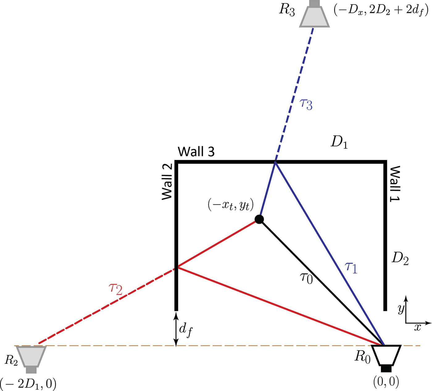
Fig. 2. Marginal radar configuration.
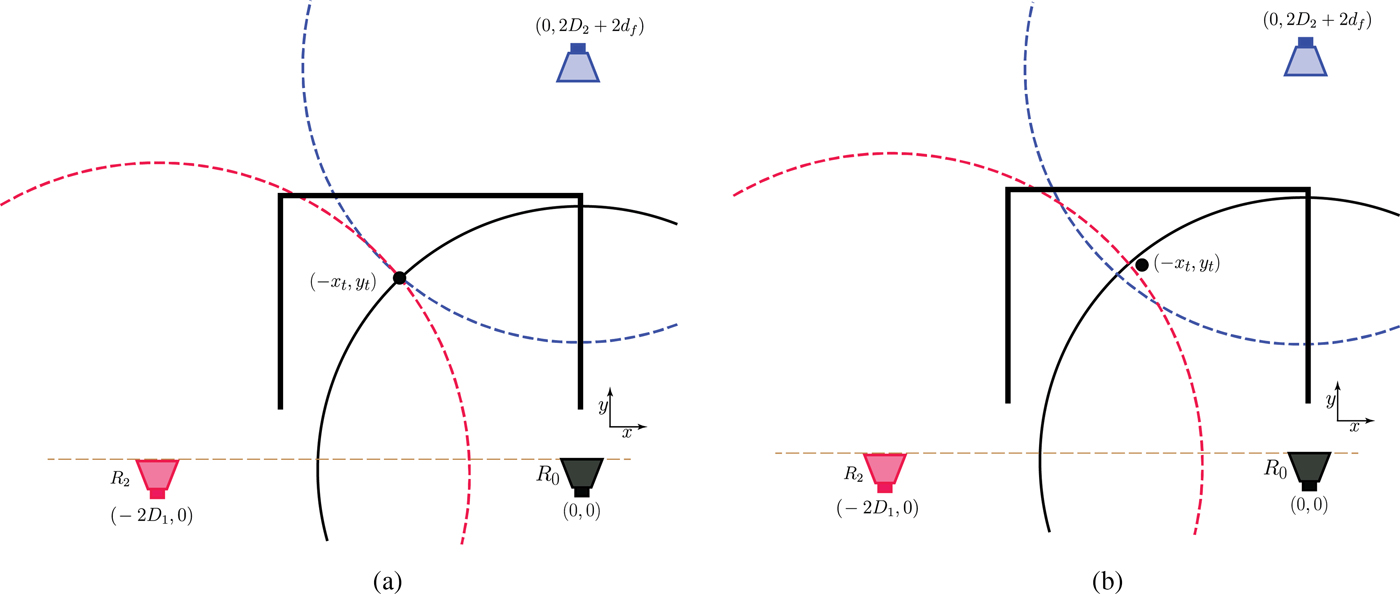
Fig. 3. Two possible wall associations: (a) correct, (b) incorrect.
If we consider the wrong association of the time delays to their respective walls, we solve (5), (6), and (7) with τ 2 and τ 3 interchanged as depicted in Fig. 3(b). Multipath return due to the presence of wall-2 is position dependent and may not exist all along. However, the direct and back-wall returns always exist. Based on the geometry presented in Fig. 2, the condition to have multipath from wall-2 is:
 $$\displaystyle{{D_1y_t} \over {(2D_1 - x_t)}} \gt d_f.$$
In target positions where multipath due to wall-2 cannot be observed, it reduces the number of possible combination to only one as shown by the floor plan in Fig. 4. This reduction happens during wall association process. In Fig. 4, an exhaustive search of possible target locations was carried out to study the effect of target location to the complexity of the proposed scheme. The scene of around 6 × 4 m2 was descritized to 30 × 30 pixels and each pixel assumes a target location. In some locations within the room marked 1, the condition in (8) is not met leading to one possible wall association, which greatly reduces the complexity of the scheme. Otherwise, there are two possible wall associations, which need to be examined for correct localization.
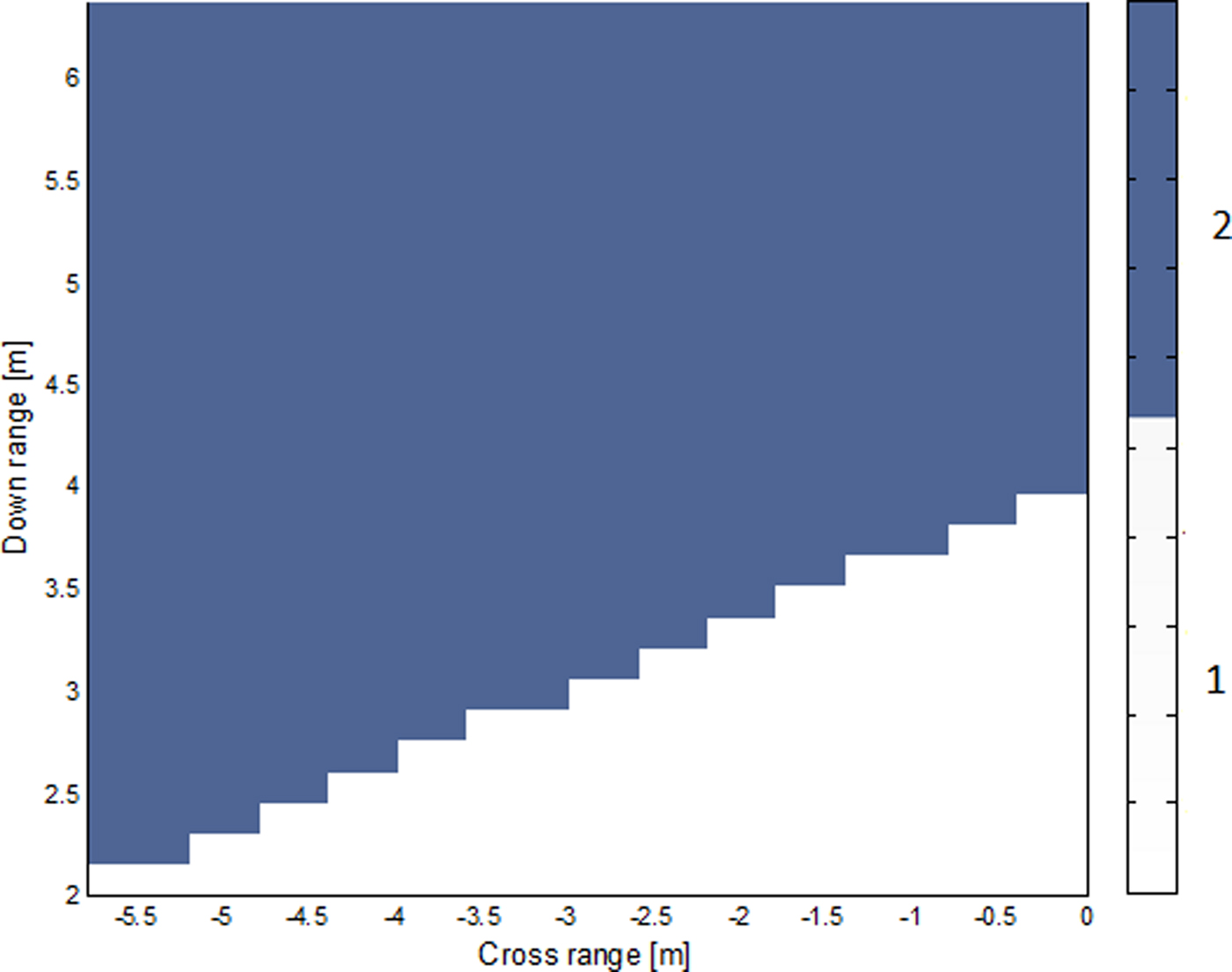
Fig. 4. Regions showing the number of possible solutions.
Let z and w represent solutions when considering correct and incorrect time delays associations with the available walls, respectively. The solution will be valid if it satisfies equations (5)–(7).
Consider correct wall association scenario with z 12 = (−x t , y t ) represents the point of intersection of (5) and (6), and z 13 is the intersection of (5) and (7). Ideally, the solution, z 13, will be declared valid if z 13 = z 12. In the presence of timing errors, the solution will be valid if and only if:
 $${\bi z}_{12} - {\bi z}_{13} = \delta _z{\rm \;} $$
δ z is the residual showing the deviation of the two intersections z 12 and z 13, assuming correct wall association as shown in Fig. 3(a). The selection of z 12 and z 13 is due to the fact that it is easier to estimate the direct arrival time than multipath returns and also the multipath from wall-2 does not exist for all possible target locations. This explains why z 23, is not a best candidate to consider for localization.
For a given received multipath, we need to find out from which wall it was generated. This scheme therefore, needs to examine both wall association scenarios as depicted in Fig. 3. Solving (5) and (6) gives:
 $${\bi z}_{12} = \left( {D_1 - \alpha, \sqrt {c^2\tau _2^2 - {\left( {D_1 + \alpha} \right)}^2}} \right).$$
Similarly, solving (5) and (7) we have:
 $${\bi z}_{13} = \left( {\sqrt {c^2\tau _3^2 - {\left[ {D_2 + d_f + \beta} \right]}^2}, D_2 + d_f - \beta} \right),$$
where
 $\alpha = c^2/4D_1(\tau _2^2 - \tau _0^2 )$
and
$\alpha = c^2/4D_1(\tau _2^2 - \tau _0^2 )$
and
 $\beta = c^2/4(D_2 + d_f)(\tau _3^2 - \tau _0^2 )$
. For the wrong wall association, the corresponding solutions,
w
12 and
w
13 are similar to (10) and (11), respectively, with τ
2 and τ
3 interchanged. The residual of the wrong wall association, δ
w
is equivalent to (9) with
z
replaced by
w
.
$\beta = c^2/4(D_2 + d_f)(\tau _3^2 - \tau _0^2 )$
. For the wrong wall association, the corresponding solutions,
w
12 and
w
13 are similar to (10) and (11), respectively, with τ
2 and τ
3 interchanged. The residual of the wrong wall association, δ
w
is equivalent to (9) with
z
replaced by
w
.
To correctly associate the returns to their respective walls, δ z needs to be smaller than δ w . This gives a clear distinction of the correct wall association from incorrect one. For better performance of the scheme, δ z should be small enough and less than δ w . The variation of residual with target location for the wrong hypothesis is shown in Fig. 5. The horizontal axis represents possible target location along the cross-range and the vertical axis shows the target location along the range direction. The amount of residual is represented in color scale, which increases from white to black as shown in Fig. 5 and interpreted by the color bar. It can be inferred from Fig. 5 that along the diagonal of the given room, the residual value when considering the wrong association is minimal. In such scenarios, the wall association is no longer important. This is due to the symmetry with respect to delay times. The two delays from the left and back walls are more or less the same. In the lower right corner, no multipath is received from wall-2 and therefore, the residual is no longer important.
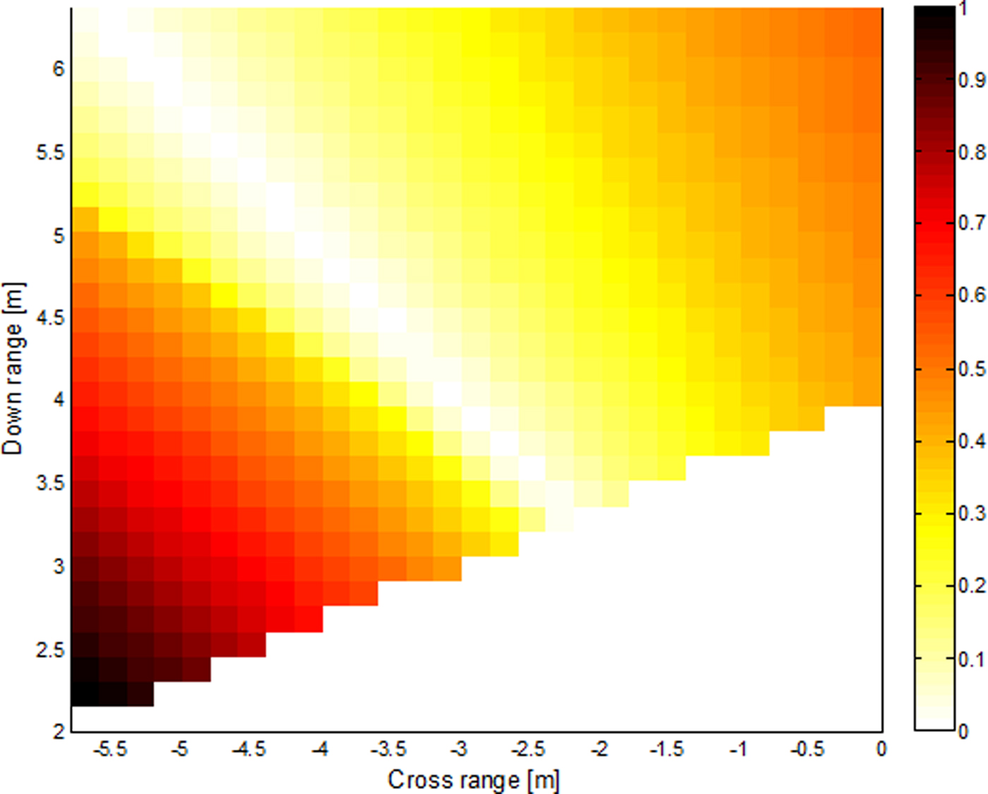
Fig. 5. Variation of residual with target locations for wrong wall association.
IV. SIMULATION RESULTS
Simulating the scene model in Fig. 2, with a target at (−3.69, 3.6) m, randomly located. The right and left sidewalls are located at the origin and at a cross-range of −5.8 m, respectively. The back wall resides at 6.37 m downrange. An UWB signal of bandwidth 2 GHz shown in Fig. 6(a) was transmitted and received by the radar located along the right wall at a standoff distance of 2 m. The received signal is pre-processed to mitigate the contribution of the front wall as in [Reference Yoon and Amin14–Reference Tivive, Bouzerdoum and Moeness17]. The direct return, the first and second reflections associated with the two walls were recorded as depicted in Fig. 6(b) The time delay between the radar and the target, τ 0 = 17.18 ns, the time delay associated with the two VRs, τ 2 = 52.36, and τ 3 = 32.86 ns.

Fig. 6. (a) Transmitted UWB signal. (b) Received signal with multipath.
When the delays are incorrectly associated with their respective walls, the target was incorrectly localized as shown in Fig. 7. The correct ordering of the delays is achieved by evaluating the residuals in (9) for the two possible arrival sequences. Under ideal condition, δ z is expected to be negligible and less than δ w except when the target lies along the diagonal of the room joining the radar. In such a case, wall association is no longer needed. It is desired that the residual varies slowly when the system is subjected to timing errors. Once the wall association is achieved, the target location is given by (11). Sensitivity of the residual value to the timing error can be taken as a reasonable performance measure of the localization scheme.
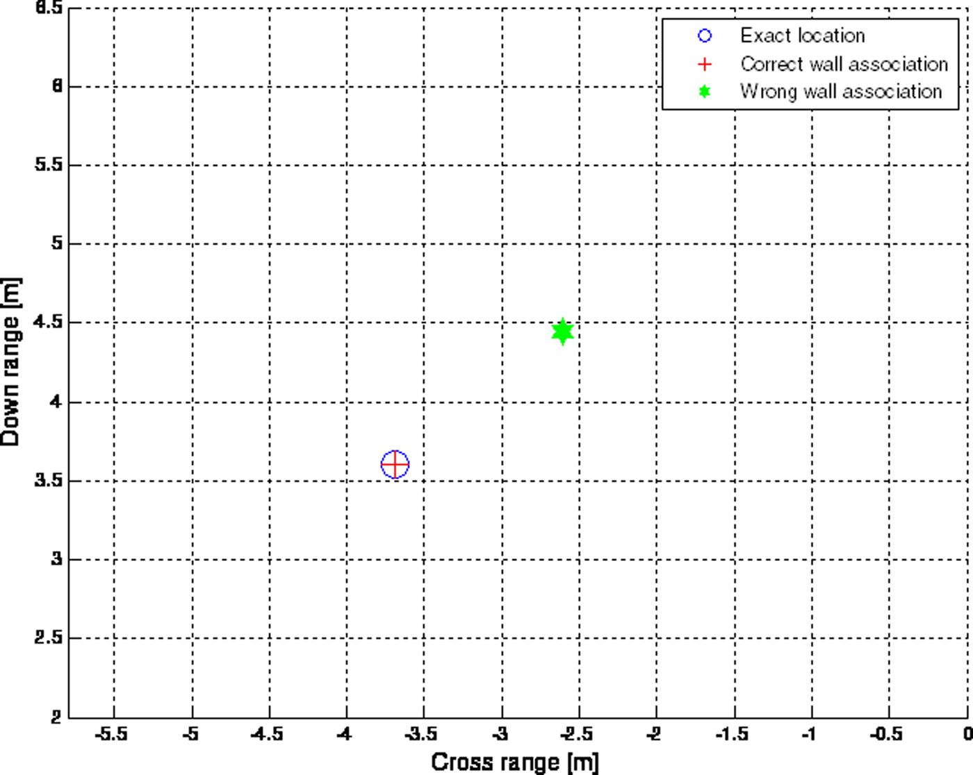
Fig. 7. Target localization with and without correct wall association.
V. SENSITIVITY DUE TO TIMING ERRORS
To evaluate the performance of the proposed scheme, 1000 randomly generated targets were localized individually. During simulation, range measurement error due to limited bandwidth and SNR were assumed from −3 to 3 ns to investigate the robustness of the proposed method. The variation of residual values with timing errors is shown in Fig. 8. From the results, it is noted that the amount of residual for correct wall association is more sensitive to multipath return from the back wall and less affected by the multipath return due to side wall as shown in Figs 8(a)–8(c). In Fig. 8, it is assumed that the remaining returns are correctly registered.
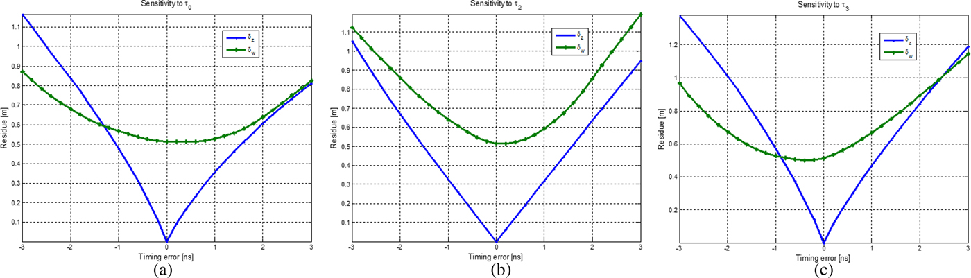
Fig. 8. Sensitivity to timing errors.
As long asδ z < δ w , the scheme associates the registered delays correctly to their respective walls and the probability of correct localization increases. It can be deduced from the graph that the scheme is accurate and precise over a reasonable range of timing errors.
A) Localization error
When perfect wall association is achieved, we need to investigate the localization error of the proposed scheme.
Let Δτ 0 and Δτ 3 represent the timing errors associated with direct return, and return from the back wall, respectively. Suppose that the estimated target location is(x t + Δx t , y t + Δy t ). The possible error in cross-range direction is given by:
 $$\Delta x_t = \left \vert {\displaystyle{{\partial x_{13}} \over {\partial \tau _0}}} \right \vert \Delta \tau _0 + \left \vert {\displaystyle{{\partial x_{13}} \over {\partial \tau _3}}} \right \vert \Delta \tau _3.$$
Similarly, the possible downrange error is
 $$\Delta y_t = \left \vert {\displaystyle{{\partial y_{13}} \over {\partial \tau _0}}} \right \vert \Delta \tau _0 + \left \vert {\displaystyle{{\partial y_{13}} \over {\partial \tau _3}}} \right \vert \Delta \tau _3.\; $$
From (12) and (13), the maximum location error, Δr: the displacement of the estimated target from the exact location, given by:
 $$\Delta r = \sqrt {{\rm \Delta} x_t^2 + {\rm \Delta} y_t^2}. $$
The expressions for the partial derivatives in (12) and (13) can be shown to be:
 $$\displaystyle{{\partial x_{13}} \over {\partial \tau _0}} = \displaystyle{{(c^2/2(D_2 + d_f))(D_2 + d_f + \beta )\tau _0} \over {\sqrt {c^2\tau _3^2 - {(D_2 + d_f + \beta )}^2}}}, $$
 $$\displaystyle{{\partial x_{13}} \over {\partial \tau _3}} = \displaystyle{{c^2\tau _3 - (c^2/2(D_2 + d_f))(D_2 + d_f + \beta )\tau _3} \over {\sqrt {c^2\tau _3^2 - {(D_2 + d_f + \beta )}^2}}}, $$
 $$\displaystyle{{\partial y_{13}} \over {\partial \tau _0}} = \displaystyle{{c^2} \over {2(D_2 + d_f)}}\tau _0\;, $$
 $$\displaystyle{{\partial y_{13}} \over {\partial \tau _3}} = - \displaystyle{{c^2} \over {2(D_2 + d_f)}}\tau _3.$$
Figure 9 shows the variation of maximum location error with timing errors due to direct and back-wall returns. It can be inferred that the scheme is stable over wide range of timing errors. The location error is more pronounced when the timing errors change in the same directions. From the expressions of partial errors, we can also deduce that we can localize more accurately when the room is large.
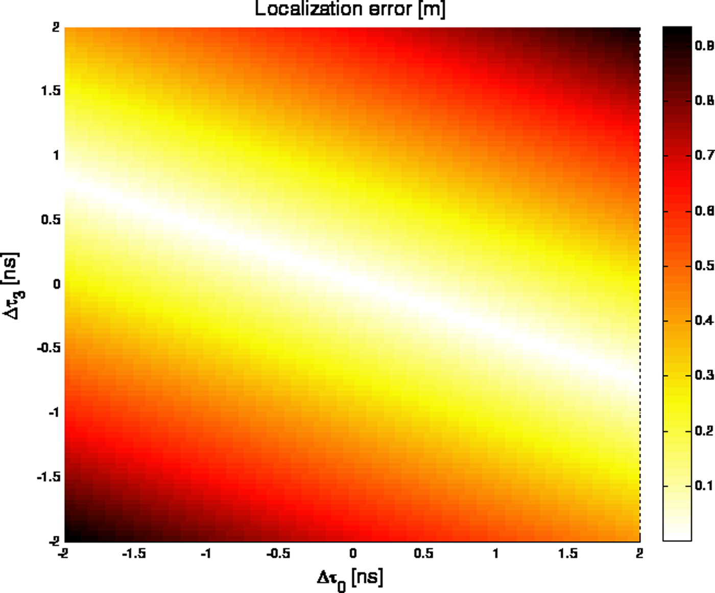
Fig. 9. Variation of localization error with timing errors.
VI. CONCLUSION
We proposed a target localization scheme with single marginal transceiver, which takes into account VR information. Based on aspect dependence of multipath returns, the antenna was located in the vicinity of the side wall to minimize wall ambiguity and reduces the number of possible solutions making the scheme more efficient. . The correct wall association was made possible by considering three monostatic configurations: using the real radar and two VRs. The analytical solution for the possible target location was obtained. To ensure the maximum number of needed returns for localization, pre-processing the received signal might be needed, including the thresholding and time gating. The effectiveness and robustness of the proposed scheme were shown using simulation results. It was shown through simulated measurement that the scheme is robust to wide range of timing errors. As the extension of this work, the scheme can be improved to multiple target scenario.
ACKNOWLEDGEMENTS
This work is funded by the National Plan for Science, Technology and Innovation (Maarifah) – King AbdulAziz City for Technology – through the Science and Technology Unit at King Fahd University of petroleum and Minerals (KFUPM), The Kingdom of Saudi Arabia, award number 15-ELE4651-04.
 Ali H. Muqaibel received the B.Sc. and M.Sc. degrees from King Fahd University of Petroleum and Minerals (KFUPM), Dhahran, Saudi Arabia, in 1996 and 1999, respectively, and the Ph.D. degree from Virginia Polytechnic Institute and State University (Virginia Tech), Blacksburg, in 2003. During his study at Virginia Tech, he was with both the Time Domain and RF Measurements Laboratory and the Mobile and Portable Radio Research Group. He is currently the Director of the Telecommunications Research Laboratory (TRL) and an Associate Professor with the Electrical Engineering Department, KFUPM. His main area of interest includes Ultra-Wideband (UWB) signal processing for localization and communications. He was a visiting scholar at both Georgia Institute of Technology, GA, USA and Villanova University, Villanova, PA, USA. He is the author of two book chapters and more than 90 articles. Dr. Muqaibel received many awards in the excellence in teaching, advising, and instructional technology.
 Abdi T. Abdalla received the B.Sc. degree in Electronic Science and Communication and M.Sc. degree in Electronics Engineering and Information Technology from the University of Dar es Salaam, Tanzania, in 2006 and 2010, respectively, and the Ph.D. degree from King Fahd University of Petroleum and Minerals (KFUPM), Saudi Arabia, in 2016. Currently, he is a Lecturer at the Department of Electronics and Telecommunication Engineering of University of Dar es Salaam, Tanzania. His research interests include target localization, sparse arrays processing, through-the-wall radar imaging, and application of compressive sensing to radar signal processing.
 Mohammad T. Alkhodary received his B.S. degree in Communication Engineering from the University of Science and Technology in 2008. He joined the Electrical Engineering Department at King Fahd University of Petroleum and Minerals (KFUPM) in 2009 as a research assistant. In 2011, he received his M.S. in Telecommunication Engineering from the same institute, and joined again to the same department as a Lecturer in 2013. In 2017, he received his Ph.D. in Electrical Engineering from KFUPM. In 2015, he received a 1-year research-internship at King Abdullah University of Science and Technology (KAUST). In 2017, he was a visiting scholar at the Center for Energy and Geo Processing (CeGP) at Georgia Tech, GA, USA. His research interests include, radar imaging, UWB communication, Compressive Sensing theory, Bayesian methods and applications.


