


Introduction
In the present scenario, circularly polarized (CP) antennas have widely gained attention finding their application in various wireless systems such as Satellite Communication, Global Positioning System (GPS), etc. Compactness followed by multiband operation of CP antenna has been an inspiration for various researchers in wireless communication systems. Various antennas such as slot antenna [Reference Baek and Hwang1–Reference Jaiverdhan, Sharma and Yadav5], fractal antenna [Reference Zhangfang, Wei, Yuan, Yinping and Yongxin6–Reference Oraizi and Hedayati8], monopole antenna [Reference El Misilmani, Al-Husseini, Kabalan and El-Hajj9, Reference Chen and Chen10] have been extensively designed to obtain multiband. The use of annular ring antennas [Reference Chen and Wong11–Reference Kanaujia and Vishvakarma13] has also become a very promising applicant for multiband applications because of their simple structure and design flexibility in obtaining miniaturization. For generation of CP waves, many techniques were adopted by researchers which included the perturbation method [Reference Ahmed, Shaalan and Awadalla14, Reference Kim, Yoon and Yang15], slots [Reference Chang and Han16, Reference Nasimuddin, Chen and Qing17], slits [Reference Jou, Wu and Wang18], metamaterial [Reference Yu, Yang and Elsherbeni19–Reference Jung and Lee21], stacking [Reference Pozar and Duffy22,Reference Falade, Rehman, Gao, Chen and Parini23], etc. Using the above techniques, many designs have been reported by various researchers to obtain triple-band [Reference Zhou, Chen and Volakis24, Reference Patil, Singh, Kanaujia and Yadava25] and dual-band [Reference Patil, Singh, Kanaujia and Yadava26, Reference Sun, Zhang and Feng27] CP antennas. In [Reference Rao, Smolinski, Quach and Rosario28] by using quadrature feeding, an F antenna was designed and was able to generate right-hand circularly polarized (RHCP) waves in all the three GPS bands L1, L2, and L5 but led to poor gain in the L1 band due to the air gap in the stacking of two substrates. In [Reference Bao and Ammann29] dual-band circular patch antenna with two concentric annular rings with slot-loaded ground plane was designed to achieve dual-band CP but it suffered from poor front-to-back ratio due to diffraction from the slots in the ground plane. In [Reference Choudhary, Srivastava and Kumar30] a dual-band CP antenna is discussed for GPS L5 and SDARS bands. In [Reference Ramirez, Parron, Gonzalez-Arbesu and Gemio31] a dual-band CP antenna having concentric annular rings and fed by four apertures was designed to obtain RHCP waves in the two bands. The above design lacked simplicity as phase shifters and Wilkinson power combiners were implemented to produce the required circular polarization. In [Reference Wang-Ta, Tze-Hsuan and Jean-Fu32] a cavity-backed annular slot antenna was designed with a dimension of 80 × 80 mm2 dual-band L1 and L2, and CP is achieved with low gain in the two bands. In [Reference Bilgic and Yegin33] the GPS antenna is proposed by modifying an annular ring and the SDARS antenna is placed at the ring center using a slot-loaded degenerate mode square patch. In [Reference Ting, Hao and Xi-Zheng34] a Y-shaped monopole antenna was designed which achieved triple band at 2.4, 3.5, and 5.8 GHz and with dual-polarization at the first and third band but <2.5 dBi gain in all the bands. In [Reference Raheja, Kanaujia and Kumar35], a triple-band CP antenna was designed by stacking a truncated square microstrip antenna with an ellipse-shaped microstrip antenna. The above antenna showed CP characteristics at the first two bands 4.2 and 4.8 GHz with linear polarization characteristic in the third band of 5.8 GHz, but the stacking process led to a lack of compactness in size. Thus, the literature survey led to the conclusion that to obtain multiband antenna generating CP waves along with the performance of antenna in terms of gain, impedance bandwidth, AR bandwidth improving and achieving miniaturization of the antenna is a challenging task.
In this article, with the aim of achieving compactness followed by achieving multiband and observing CP characteristic, a novel triple-band dual-polarized annular ring antenna is proposed. In this design by implementing two layers of concentric ring around an annular ring leads to the generation of three bands showing circular polarization in the first two bands and linear polarization in the third band. A detailed theoretical approach is presented by the approach of the equivalent circuit and the simulation analysis is done using CST Microwave Studio matching well the measured results. The proposed antenna has an attractive feature of being simple with a low profile for achieving the desired frequency of L2 and L1 bands and thus making the above structure finding its application for GPS with RHCP in the two bands having 3 dB beamwidth of 107.70 and 119.32° respectively.
Design and theoretical analysis
Figure 1 shows concentric annular ring microstrip antenna (CARMSA). The inner annular ring patch antenna (P1) is coaxially fed whereas the other two concentric rings (P2 and P3) surround the patch. The outermost concentric annular ring P3 is having two notches placed symmetrically on it to get the desired resonating frequency and improved axial ratio. The proposed structure is built on FR4 substrate (relative permittivity 4.4) of height 1.6 mm. The ground plane of L × L is embedded with a cross slot of lc1 × wc1 and lc2 × wc2. To get the desired resonant frequency, the two notches are etched inside the outermost concentric annular ring. The vertex of symmetrical notches is at (16.82, 0.75), (16.82, −0.75), (17.43, −1), and (17.43, 1) in mm. Table 1 shows the dimensional parameters of the proposed antenna.

Fig. 1. Geometry of proposed antenna. (a) Top view. (b) Bottom view.
Table 1. Parameters of the proposed antenna

DGS unit can be modeled as parallel R, L, and C resonant circuit as in Fig. 2(a), which is connected at both ends to transmission lines [Reference Kunwar, Gautam and Rambabu36].

Fig. 2. Equivalent circuit model of (a) cross slot and (b) proposed CARMSA.
The concentric annular ring microstrip patch can be represented by an equivalent circuit as shown in Fig. 2(b). This circuit includes a parallel combination of resistance R1, inductance L1, and capacitance C1, which represent the unit cell of annular ring patch P1. Annular ring P2 is represented as a parallel combination of resistance R2, inductance L2, and capacitance C2. Rings P1 and P2 are coupled with a parallel plate capacitance (Cs1) and two fringing capacitances (Cp1). Similarly, the outer most ring P3 (parallel combination of R3, L3, and C3) is coupled with P1 and P2 by a parallel plate capacitance (Cs2) and two fringing capacitances (Cp2) [Reference Kanaujia and Vishvakarma37]. A coupling capacitance (Cs3) is considered between the slot integrated ring and without the slot integrated ring which is connected in series with parallel combination of Rn, Ln, and Cn. Coaxial feed is represented by series combination of resistance Rf and inductance Lf as shown in Fig. 2(a).
The total input impedance of the equivalent circuit (Zeq) can be expressed as [Reference Singh, Gangwar and Kanaujia38]:

where Zn = (1/Rn + jωLn + (1/jωCn)) is the input impedance of symmetrical notches.
Zp = equivalent impedance of coupled P1, P2, and P3.
Components of the equivalent circuit R1, L1, and C1 can be expressed as [Reference Singh, Gangwar and Kanaujia38]:

where $F( b ) = ( {j_n( {kb} ) y_n^{\prime} ( {ka} ) -y_n( {ka} ) j_n^{\prime} ( {kb} ) } ) , \;$
where a is the inner radius and b the outer radius of annular ring, ɛr is the relative permittivity of the substrate, ε 0 is the free space permittivity, d is the feed point, k is the resonant wave number, h is the thickness of the substrate, μ 0 is the permeability of free space, $\varepsilon _n = \sqrt 2$ (for n ≠ 0), ɛn = 1 (for n = 0).


where Q 0 is a factor including radiation, conductor, and dielectric losses.
Evolution stages of the proposed antenna
The evolution of our proposed antenna started with a coaxial fed annular ring antenna (i) of inner radius R1 and outer radius R2. The ground plane of the antenna was loaded with cross slot. As seen in the figure, this proposed antenna resonates at 2.16 GHz and achieves a bandwidth of 78.279 MHz (2.1183–2.1966 GHz) with linear polarization at 2.16 GHz. A concentric ring of inner radius R3 and outer radius R4 is made to surround the antenna (i) to shift the resonant frequency of the antenna to the lower side of 1.295 GHz. As depicted in Fig. 3, the impedance bandwidth achieved is 71.12 MHz (1.2572–1.3283 GHz). The axial ratio of 5.62 dB at 1.295 GHz is obtained. To get triple band, a second concentric annular ring of inner radius R5 and outer radius R6 is introduced which generates three bands at 1.22760, 1.57542, and 2.18 GHz of impedance bandwidth 54.032, 105.43, and 52.057 MHz, respectively. Figure 4 depicts that CP waves are also generated at 1.22760 GHz having an AR bandwidth of 12 MHz (1.222–1.234 GHz) with LP waves generated at 1.57542 and 2.18 GHz. A notch is introduced in the second concentric ring, and it is observed that the resonant frequency shifts to desired three bands being generated at 1.22760, 1.57542, and 2.18 GHz. It is also observed from this figure, dual CP band is at 1.22760 and 1.57542 GHz with AR bandwidth of 14.30 MHz (1.2221–1.2364 GHz) and 13.60 MHz (1.5630–1.5766 GHz), respectively. The axial ratio of 0.73 dB at 1.22760 GHz and 2.81 dB at 1.57542 GHz is obtained.

Fig. 3. Variation of simulated S 11 with frequency of evolution of antennas.

Fig. 4. Variation of axial ratio with frequency of evolution of antennas.
Parametric study of proposed antenna
To get the desired frequency band, a parametric analysis was carried on the proposed antenna by varying the dimensions of the cross slot in the ground plane and their effect on S 11 and axial ratio with frequency was studied.
Influence of length lc2
Variation of lc2 on the S 11 and axial ratio with frequency is observed in Figs 5(a) and 5(b). As lc2 is considered at 35.50, 35.75, 36, 36.25, and 36.65 mm, it is observed that the resonant frequency of the proposed antenna is achieved at 1.2350, 1.2325, 1.2310, 1.2295, and 1.22760 GHz, respectively. Thus, it is observed that as length increases from 35.50 to 36.65 mm, resonating frequency shifts toward lower frequency to achieve GPS L2 band at resonating frequency of 1.22760 GHz. From Fig. 5(b) it is also observed that axial ratio improves at 36.65 mm with axial ratio value approaching the ideal value of 0.73 dB from 5.62 dB as length increases. Thus, the value of lc2 is set to 36.65 mm.

Fig. 5. (a) Influence of length lc2 on S 11 versus frequency. (b) Influence of length lc2 on axial ratio versus frequency.
Influence of length wc1
Variation of wc1 on the S 11 and axial ratio with frequency is observed in Figs 6(a) and 6(b). As wc1 is considered at 33.50, 33.75, 34, 34.25, and 34.57 mm, the value of S 11 shifts toward upper frequency to achieve GPS L1 band at resonating frequency 1.57542 GHz and better impedance matching is observed at 34.57 mm. It is also observed that axial ratio improves at 34.57 mm with axial ratio value approaching the ideal value of 2.81 dB at desired frequency 1.57542 GHz from 5.56 dB as the value of wc1 increases from 33.50 to 34.57 mm. Thus, the value of wc1 is finalized to 34.57 mm.

Fig. 6. (a) Influence of length wc1 on S 11 versus frequency. (b) Influence of length wc1 on axial ratio versus frequency.
Results and discussion
By using the Agilent vector analyzer (N5230A: PNA-L), the fabricated model of the proposed antenna is obtained. Figure 7 depicts the top and bottom view of the fabricated prototype of the proposed antenna. Figures 8 and 9 show the vector surface current and electric field distribution that are analyzed by varying the time phase at 0, 90, 180, 270° at 1.22760 and 1.57542 GHz, respectively. At 0 and 90°, the vector surface current and electric field are of the equal magnitude and are in-phase opposition at 180 and 270°, respectively. This concludes that as there is change in the phase, and the simulated surface current vectors and electric field rotate in the anticlockwise direction, demonstrating that RHCP is achieved.
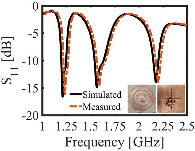
Fig. 7. Simulated and measured S 11 of proposed antenna.

Fig. 8. Surface current distribution at 1.22760 and 1.57542 GHz for the signal excitation at t = 0, that is, 0° phase, t = T1/4, that is, 90° phase, t = T1/2, that is, 180° phase and t = 3T1/4, that is, 270°.
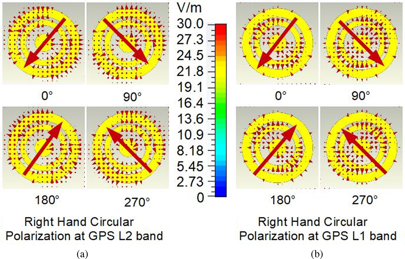
Fig. 9. Electric field distribution at 1.22760 and 1.57542 GHz for the signal excitation at t = 0, that is, 0° phase, t = T1/4, that is, 90° phase, t = T1/2, that is, 180° phase and t = 3T1/4, that is, 270°.
Figures 7 and 10 depict that the proposed antenna achieves measured impedance bandwidth of 49.50 MHz (1.1994–1.2489 GHz), 94.10 MHz (1.5444–1.6385 GHz), and 52.60 MHz (2.1550–2.2076 GHz) and AR bandwidth of 15.50 MHz (1.2239–1.2394 GHz) and 14.20 MHz (1.5651–1.5793 GHz) which has good agreement with simulated ones. These results satisfy the desired frequency of GPS L2, GPS L1, and UMTS bands. Figure 11 depicts the simulated axial ratio beamwidth of 107.70 and 119.32° for GPS L2 and GPS L1 bands.

Fig. 10. Simulated and measured axial ratio of proposed antenna.

Fig. 11. Axial ratio of the designed antenna exhibits wider beamwidth.
The gain of the proposed antenna varying with frequency is illustrated in Fig. 12. It is observed from radiation patterns that the simulated gain attains the value of 3.32 dBic in the first band, 3.54 dBic in the second band, and 3.83 dBic in the third band. The simulated results match closely with the measured gain of 3.31, 3.55, and 3.5 dBic in the three bands. This figure shows the radiation pattern at 1.22760, 1.57542, and 2.18 GHz for E and H planes.

Fig. 12. Radiation pattern of proposed antenna at GPS L2, GPS L1, and UMTS bands.
Figures 12(d) and 12(e) depict the radiation pattern for simulated RHCP of the proposed antenna for both GPS L2 and GPS L1 frequency bands. Observation shows that the pattern is symmetrical for GPS L2 band and its RHCP is greater than left-hand CP by 27 dB and for GPS L1 band RHCP is greater than left-hand CP by 16 dB in the ϴ = 0° direction for both planes. In Table 2 comparison of the proposed antenna with the previously reported antenna is listed. LHCP 0° means that at a constant value of φ = 0° radiation pattern is dominating in RHCP than left-hand CP and LHCP 90° means that at a constant value of φ = 90° radiation pattern is dominating in RHCP than left-hand CP.
Table 2. Comparison of our proposed antenna with some reported CP antennas in the literature

Conclusion
A novel structure single-feed triple-band CARMSA has been presented. The proposed antenna depicts a simple structure with compactness and shows RHCP for two bands with linear polarization in one band. Gain of 3.32, 3.54, and 3.83 dBi is achieved in three bands at 1.22760, 1.57542, and 2.18 GHz, respectively. Thus, the proposed antenna finds a good prospective for GPS L2, GPS L1, and UMTS bands which make this suitable for the automotive applications.
Conflict of interest
None.
 Surya Deo Choudhary received his Ph.D. degree in Electronics and Communication Engineering from B.R. Ambedkar Bihar University in 2014, his Master of Technology Degree from BIT Sindri, Dhanbad under Vinoba Bhave University in 2011, and his Bachelor (B.Sc. Engineering) in 2008 from the same University. Presently, he is working as an Associate Professor and Deputy Head of Electronics and Communication Engineering Department, Noida Institute of Engineering and Technology, Greater Noida, India. He has wide teaching experience as an Assistant Professor in the Department of ECE, DAV Institute of Engineering & Technology (A joint venture of the Government of Jharkhand & DAVCMC). He has more than 10 years of teaching and research experience. His research interests include organic semiconductor materials, antenna and microwave engineering. He has published many national and international journals. He is a Life Member of the International Association of Engineers (IAENG) and the Indian Society for Technical Education (ISTE).
 Shilpee Patil received her Ph.D. degree in Electronics Engineering from AKTU, Lucknow, India in 2019, her Master of Technology degree in Digital Communication from GGSIP University, Delhi, India, in 2009. She received her B.Tech. degree in Electronics & Communication Engineering from AKTU, Lucknow, India. Shilpee Patil currently is working as an Associate Professor in the Department of Electronics & Communication Engineering in NIET, Greater Noida, India. She has more than 11 years of teaching and research experience. She has a keen research interest in design and modeling of microstrip antenna for wireless communications. She has published many national and international journals. She has attended various training programs in the area of Electronics & Communication Engineering. She is a reviewer of several journals of international repute, i.e. IEEE Access, Journal of Electromagnetic Wave and Application, International Journal of Electronics, etc.
 Alka Verma received her B.E. degree in Electrical & Electronics from Bangalore University, Karnataka, India. She has completed her M.Tech. degree in Electronics Engineering from Dr. A.P.J Abdul Kalam Technical University (formerly UPTU), Lucknow (U.P.), India and currently pursuing her Ph.D. degree from the same. Her areas of interest are microstrip antennas, electromagnetic band gap structures, and circularly polarized microstrip antennas for wireless communications.
 Md Irshad Alam has received his Ph.D. degree in Electrical Engineering from B.R. Ambedkar Bihar University in 2014, his Master of Technology Degree from BIT Sindri, Dhanbad under Vinoba Bhave University in 2011, and his B.Tech. from MIT, Muzaffarpur. Presently he is working as an Assistant Professor of Electrical Engineering Department, Sitamarhi Institute of Technology, Sitamarhi, Bihar, India. His research interests include power system, control system, and organic semiconductor materials.
 Vinod M. Kapse is working as a Professor and Director at Noida Institute of Engineering & Technology, Greater Noida since March 2019. He obtained his Bachelor's Degree in Industrial Electronics from Amaravati University, Amaravati, and M.Tech. in Electronics Engineering from Nagpur University, Nagpur. He has done his Ph.D. degree in Electronics Engineering in 2014 from Jabalpur Engineering College, RGPV University, Bhopal. He had started his career in Industry as a VLSI Design Engineer with Sibar Software Services Pvt. Ltd., Hyderabad. He has started his teaching career at Guru Ramdas Khalsa Institute of Science Technology, Jabalpur in 2002 as a lecturer. Later in 2002, he joined Gyan Ganga Institute of Technology & Sciences, Jabalpur and worked as HOD & Professor in the ECE Department and Principal of the Institute. His research areas comprise VLSI design, digital system design and robotics, etc. He has published more than 50 research papers in international/national journals.
 Prof. Binod Kumar Kanaujia is working as a Professor in the School of Computational and Integrative Sciences, Jawaharlal Nehru University, New Delhi since August 2016. Dr. Kanaujia had completed his B.Tech. in Electronics Engineering from KNIT, Sultanpur, India in 1994. He did his M.Tech. and Ph.D. degrees in 1998 and 2004, respectively, from the Department of Electronics Engineering, I.I.T. B.H.U., Varanasi, India. He has a keen research interest in design and modeling of reconfigurable circular polarized antenna. He has been credited to publish more than 150 research papers. He is a reviewer of several journals of international repute, i.e. IET Microwaves, Antennas & Propagation, IEEE Antennas and Wireless Propagation Letters, Wireless Personal Communications, Journal of Electromagnetic Wave and Application, Indian Journal of Radio and Space Physics, IETE Technical Review, International Journal of Electronics, International Journal of Engineering Science, IEEE Transactions on Antennas and Propagation, International Journal of Microwave and Wireless Technologies, etc.


