INTRODUCTION
It is well-known that a classically overdense plasma can become transparent to an electromagnetic wave when its intensity is highly relativistic (Akhiezer & Polovin, Reference Akhiezer and Polovin1956). The basic concept of such a relativistic transparency (RT) is that the effective mass of electrons under the highly intense electromagnetic wave increases by the relativistic gamma factor, which results in less susceptible responses of the electron plasma to the wave. In this case, the reduced susceptibility of the plasma leads to enhanced transparency and the development of a relativistic channel for pulse propagation in overdense plasma.
As laser technologies have improved very rapidly up to the current petawatt class level, the RT does not just reside in academic interest, but it plays a crucial role in many applications. First of all, RT is, along with hole boring (Wilks et al., Reference Wilks, Kruer, Tabak and Langdon1992; Ping et al., Reference Ping, Shepherd, Lasinski, Tabak, Chen, Chung, Fournier, Hansen, Kemp, Liedahl, Widmann, Wilks, Rozmus and Sherlock2008), considered a dominant mechanism of transferring laser pulse energy deep into a classically over-critical plasma (Willingale et al., Reference Willingale, Nagel, Thomas, Bellei, Clarke, Dangor, Heathcote, Kaluza, Kamperidis, Kneip, Krushelnick, Lopes, Mangles, Nazarov, Nilson and Najmudin2009; Eremin et al., Reference Eremin, Korzhimanov and Kim2010). In addition to this important application, RT is directly or indirectly relevant to ion acceleration from thin-foil-laser interactions (Flippo et al., Reference Flippo, Hegelich, Albright, Yin, Gautier, Letzring, Schollmeier, Schreiber, Schulze and Fernández2007; Steinke et al., Reference Steinke, Henig, Schnürer, Sokollik, Nickles, Jung, Kiefer, HÖrlein, Schreiber, Tajima, Yan, Hegelich, Meyer-Ter-Vehn, Sandner and Habs2010); ion energy enhancement by relativistic transparency has recently been reported (Henig et al., Reference Henig, Kiefer, Markey, Gautier, Flippo, Letzring, Johnson, Shimada, Yin, Albright, Bowers, Fernández, Rykovanov, Wu, Zepf, Jung, Liechtenstein, Schreiber, Habs and Hegelich2009; Shorokhov et al., Reference Shorokhov and Pukhov2004). Another emerging issue is the shaping of ultraintense laser pulses by RT; overdense plasma is used as a shutter, thereby allowing the transmission of only the intense part of the laser pulse, as shuttering usually leads to pulse shortening. This scheme is plausible, since there is practically no readily available optical method for manipulating the pulse shape in over-petawatt laser regimes. Note that this form of RT-based pulse shaping was briefly addressed decades ago (Bulanov et al., Reference Bulanov, Esirkepov, Naumova, Pegoraro, Pogorelsky and Pukhov1996; Vshivkov et al., Reference Vshivkov, Naumova, Pegoraro and Bulanov1998) based on simulation results, and Ji et al. (Reference Ji, Shen, Zhang, Wang, Jin, Xia, Wen, Wang, Xu and Yu2009) have recently reported particle-in-cell (PIC) simulations of generating quasi-single-cycled, circularly polarized, ultraintense laser pulses. Experimentally, such a shaping concept was used in filtering a pedestal and amplified spontaneous emission (ASE) of a high intensity laser pulse (Reed et al., Reference Reed, Matsuoka, Bulanov, Tampo, Chvykov, Kalintchenko, Rousseau, Yanovsky, Kodama, Litzenberg, Krushelnick and Maksimchuk2009). The evolution of a high-density electron beam and generation of flying electron mirror by such a shaped pulse was studied before (Kulagin et al., 2007).
The underlying concept of RT is simple, but the modes of wave propagation or penetration have been found to be very diverse, depending on the regimes for plasma density, laser intensity, laser pulse polarization, and ion motion. Several examples include traveling of circularly (Akhiezer et al., 1956) and linearly (Max & Perkins, Reference Max and Perkins1971) polarized waves, the formation of standing waves in steady states for circular (Marburger & Tooper, Reference Marburger and Tooper1975; Lai, Reference Lai1976) and linear polarizations (Bourdier & Fortin, Reference Bourdier and Fortin1979), the formation of solitary waves (Kozlov et al., Reference Kozlov, Litvak and Suvorov1979; Kaw et al., Reference Kaw, Sen and Katsouleas1992), the penetration of a relativistic wave in a cavitated plasma (Kim et al., Reference Kim, Cattani, Anderson and Lisak2000; Tushentsov et al., Reference Tushentsov, Kim, Cattani, Anderson and Lisak2001), steady state with full reflection at the opacity-transparency boundary (Goloviznin et al., Reference Goloviznin and Schep2000), and the laser piston formation (Naumova et al., Reference Naumova, Schlegel, Tikhonchuk, Labaune, Sokolov and Mourou2009; Schlegel et al., Reference Schlegel, Naumova, Tikhonchuk, Labaune, Sokolov and Mourou2009).
In the contexts above, most have focused on the steady states of wave propagation or penetration. In contrast to such extended studies for the steady states, a dynamic procedure of how a relativistically transparent channel is formed from initially opaque plasma has yet to be sufficiently elucidated. For linear polarization, the transition from opacity to transparency by electron heating was addressed by PIC simulations (Lefebvre & Bonnaud, Reference Lefebvre and Bonnaud1995, Reference Lefebvre and Bonnaud1997); for circularly polarized waves, in addition to heating, the role of the electron bunch generation for the relativistic channeling was illustrated (Eremin et al., Reference Eremin, Korzhimanov and Kim2010). However, as we understand, the most important information of relativistic channeling is still missing: the speed of the opacity-transparency interface (henceforth referred to as the channeling speed). The channeling speed is important in predicting the final pulse shape after transmission through overdense plasma. As such, the most significant contribution of this paper is to provide a means to estimate the channeling speed for linearly polarized laser pulses. Although our phenomenological formula is one-dimensional (1D), it will be shown that it can be limitedly applied even to two dimensional (or probably three dimensional) cases.
SPEED OF RELATIVISTIC CHANNELING
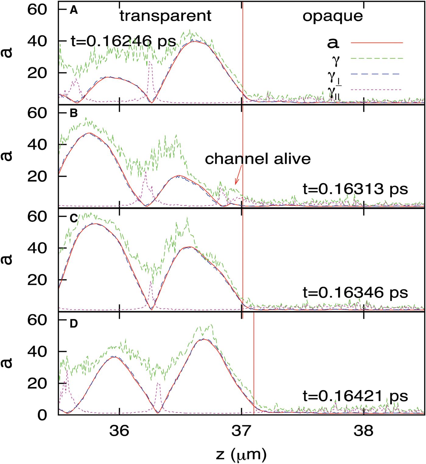
We present first the overall propagation features of a linearly polarized laser pulse in overdense plasma. Figure 1 represents snapshots from PIC simulations obtained using a 1D object oriented particle-in-cell on X-windows (XOOPIC) (Usui et al., 2000). In the figure, the normalized vector potential a is measured from the magnetic field data and average gamma factor of the electrons in the transverse and longitudinal directions is also measured. Note that  , and γ = γ⊥γ1. Here, u ⊥ = γv ⊥, where v ⊥ is the perpendicular velocity, and v z is the longitudinal velocity. The transverse gamma coincides almost perfectly with the vector potential, as is expected from
 ![]() . One unique observation in Figure 1, however, is that the longitudinal gamma is significant in the nodes, while it is relatively small in the high-a regions. This periodic structure of γ‖ implies that it is a result of collective behavior driven by the ponderomotive force, rather than that of thermal heating. Due to the large γ‖ in the low-a region, the total γ remains large enough for the pulse trains to propagate behind the front. Indeed, the figure shows that the laser pulse exhibits a standing-wave-like behavior in the transparent region because of the beating with the reflected wave. Thus, the intensity of the pulse in the first half wavelength is not preserved as in a one-way traveling wave, but instead it oscillates. As such, when the intensity of the wave front is high, it opens a relativistic channel; but even at the moment when the wave front intensity goes to zero because of the beating, the relativistic channel remains due to the strong longitudinal motion. Therefore, the next wave front can start its channel-opening from a more advanced place than its predecessor.
. One unique observation in Figure 1, however, is that the longitudinal gamma is significant in the nodes, while it is relatively small in the high-a regions. This periodic structure of γ‖ implies that it is a result of collective behavior driven by the ponderomotive force, rather than that of thermal heating. Due to the large γ‖ in the low-a region, the total γ remains large enough for the pulse trains to propagate behind the front. Indeed, the figure shows that the laser pulse exhibits a standing-wave-like behavior in the transparent region because of the beating with the reflected wave. Thus, the intensity of the pulse in the first half wavelength is not preserved as in a one-way traveling wave, but instead it oscillates. As such, when the intensity of the wave front is high, it opens a relativistic channel; but even at the moment when the wave front intensity goes to zero because of the beating, the relativistic channel remains due to the strong longitudinal motion. Therefore, the next wave front can start its channel-opening from a more advanced place than its predecessor.

Fig. 1. (Color online) Snapshots of the linearly polarized pulse, its vector potential, and gamma factors at around the transparency-opacity interface. The vertical red line represents the position at which the gamma factor becomes large enough to make the plasma transparent. In the second figure, it is seen that the gamma factor remains large even when the vector potential is small. The simulation parameters are a = 30, n = 2 × 1022 cm−3, 5 µm for the slab thickness, and 1 µm for the laser wavelength.
From here we estimate the channeling speed. Figure 2 shows the measurement of the channeling speed from 1D PIC simulations using 1D XOOPIC (Usui et al., 2000). From a series of such simulations for wide parameter ranges, we discovered that the following formula fits well to the simulation data:
where a c = ωp2/ω2. Figures 2a and 2b represents the cases for relatively moderate laser intensities and 2a a few tens of or 2b a few hundreds of critical density for the plasma, where the simulations agree quite well with the phenomenological formula.

Fig. 2. (Color online) The speed (βb) of the transparency-opacity interface as a function of the peak amplitude a of the laser pulse for various plasma densities. The electron densities used in the upper row correspond to 8.9n c, 17.9n c, 35.8n c, and 71.6n c, respectively, and the lower row to 178.9n c and 447.2n c, respectively.
We speculate roughly the origin of Eq. (1) as follows. First, we assume that the laser pulse front opens the RT channel for a limited time; the amplitude of the pulse front oscillates due to the beating with the reflected wave, and the channel is opened only when the amplitude is greater than a threshold value. The channel opening time is then estimated for one oscillation cycle, during which the pulse is assumed to propagate with the group velocity. Following this line, first, the channel opening time is approximated from a total = 2a cos ωt > a th, which yields
A factor of four exists, since this term appears four times during one oscillation cycle. The factor of two in front of a is to count the reflection at the boundary. During this channel opening time, the pulse is assumed to propagate with a group velocity (Akhiezer & Polovin, Reference Akhiezer and Polovin1956; Max & Perkins, Reference Max and Perkins1971), i.e., ![]() Then the propagation distance during one cycle is v gt open. Considering the sinusoidal nature of the channel opening time, we can heuristically average out the factor of
Then the propagation distance during one cycle is v gt open. Considering the sinusoidal nature of the channel opening time, we can heuristically average out the factor of ![]() from Eq. (2). The threshold value a th was empirically found to be 1.2a c from many simulations. Then, the average propagation speed of the transparency-opacity interface for one cycle of the oscillation (T = 2π/ω) becomes Eq. (1).
from Eq. (2). The threshold value a th was empirically found to be 1.2a c from many simulations. Then, the average propagation speed of the transparency-opacity interface for one cycle of the oscillation (T = 2π/ω) becomes Eq. (1).
We observed that Eq. (1) is also valid for two-dimensional (2D) systems in a wide range of parameters. In Figure 2, the rectangles represent the channeling speed measured from 2D PIC simulations. Here what we measured actually is the position of the pulse front at the propagation axis as a function of time. The plasma densities examined were 2 × 1022cm −3, and 4 × 1022cm −3, and the vector potential of the laser from 50 through 170. In this range, the simulation data agreed well with Eq. (1). Throughout the 2D simulations, any multi-dimensional instability such as filamentation of the laser pulse was rarely observed, probably because the slab thickness was too thin for instability to grow. Note that in the 2D simulations, the laser pulse was focused on the front surface of the plasma slab, so that the laser field is plain-wave-like inside the plasma as in one-dimensional cases.
Eq. (1) was obtained with the condition that a ≥ a c, so the simulation data deviates from the theoretical curve for a ≫ a c. In this opposite regime, the group velocity naturally approaches the vacuum speed of light c. However, because the channel opening time is limited by the standing-wave-like oscillations, the propagation speed should be roughly divided by ![]() , yielding 0.71c. This point is clearly seen in Figures 2c and 2d, where the measured values consistently converge near 0.7c as expected. Note that for such unrealistically huge a as in Figures 2c and 2d, there actually exist various nonlinear effects such as radiation damping, or atomic level interactions, which are not counted in the simulations.
, yielding 0.71c. This point is clearly seen in Figures 2c and 2d, where the measured values consistently converge near 0.7c as expected. Note that for such unrealistically huge a as in Figures 2c and 2d, there actually exist various nonlinear effects such as radiation damping, or atomic level interactions, which are not counted in the simulations.
COMPARISON OF LINEARLY AND CIRCULARLY POLARIZED PULSES
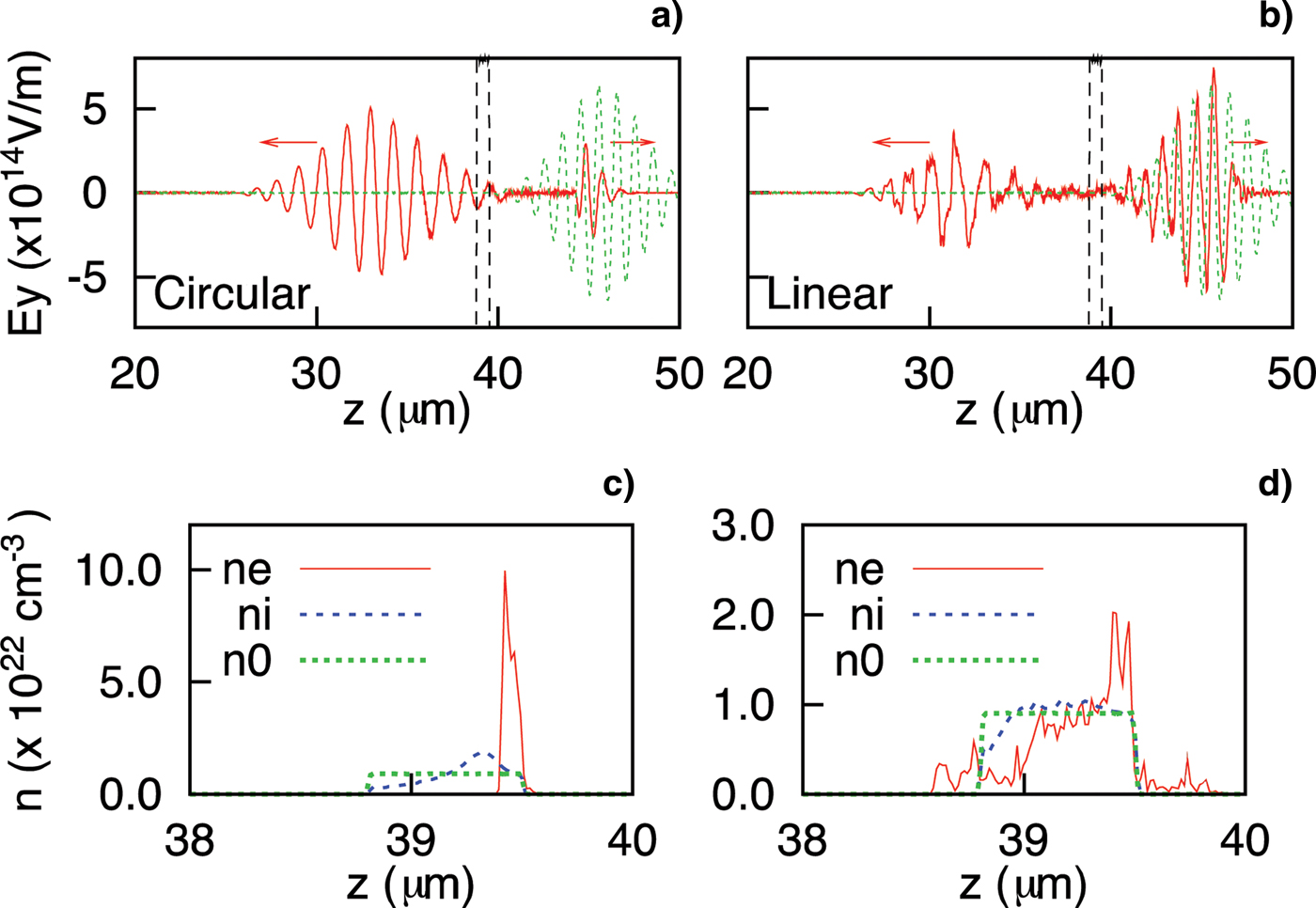
It is also useful to compare the behavior of pulse shaping in circularly and linearly polarized cases (Fig. 3). The linearly polarized case has three major differences from the circularly polarized case. First, there is no compression of the plasma slab in the linear case, whereas it is an essential step in the circular case in order to compress the slab below the nonlinear skin depth (Ji et al., Reference Ji, Shen, Zhang, Wang, Jin, Xia, Wen, Wang, Xu and Yu2009) (see Figs. 3c and 3d). Because of the oscillating part of the ponderomotive force, whose oscillation frequency is significantly below the plasma frequency, electron sheets are not consistently plowed in the linear case. Instead, a strong longitudinal oscillation of the electron plasma is induced, which keeps the channel open (as described above). Second, once the relativistic channel is formed in the linear case, it remains open for a long time, so even the weak rear part of the laser pulse propagates through the channel. Note that in the circular polarized case, both the front and rear parts of the pulse are cut out (Fig. 3a); because of these differences, the transmitted pulse of the linear polarization takes the form of a sharp-cut front and long tail (Fig. 3b). We remark that even in the linearly polarized case, however, the transparent channel is shut down more quickly when the ion motion is severe (i.e., for lighter ions), and that pulse shortening occurs in the rear part (though not as severe as in the circular case).

Fig. 3. (Color online) (a, b) Comparison of the pulse shaping for circularly and linearly polarized laser pulses. (c, d) Densities of electrons, ions, and initial plasma. In these simulations, the plasma slab was 0.7 µm-thick with density n = 0.9 × 1022 cm−3 = 8.1n c. The normalized vector potential of the laser pulse was a = 20. The ions used were protons.
The third difference, which may be the most noticeable, deals with the sensitivity of channeling to the initial slab thickness. In the circular polarization, the final thickness of the slab after compression is determined by the balance of the ponderomotive force and the Coulomb repulsion. This implies that the initial slab thickness is a critical factor affecting the transmission of a laser pulse with a given intensity; i.e., when the initial thickness is too high, the slab cannot be compressed below the skin depth and no efficient transparency can be obtained. Another consequence of this process is the reduction of the peak intensity of the transmitted pulse. In the linear polarization, however, channeling is not as dependent on the initial slab thickness, up to some range. Note that the shortening of the circularly polarized pulse in a typical petawatt regime requires an initial slab thickness of around 1 µm, whereas the linearly polarized pulse can easily transmit through several micrometers. Furthermore, since pulse-front cutting is based purely on the reflection, the peak intensity of the transmitted pulse is well preserved in the linear polarization.
Before we move on to the next subject, it is worthwhile to note the difference between the parameter regime of our work and the laser piston model (Naumova et al., Reference Naumova, Schlegel, Tikhonchuk, Labaune, Sokolov and Mourou2009; Schlegel et al., Reference Schlegel, Naumova, Tikhonchuk, Labaune, Sokolov and Mourou2009). In this model, they derived the propagation speed of the “piston,” which is represented by a double layer structure of the “snow-plowed” electron sheet and the relatively slow ion sheet. Such a snow-plowing is typical in circularly polarized wave. In our work, where we used the linear polarized wave, we did not observe such a strong snow-plowing. Naumova et al. (Reference Naumova, Schlegel, Tikhonchuk, Labaune, Sokolov and Mourou2009) and Schlegel et al. (Reference Schlegel, Naumova, Tikhonchuk, Labaune, Sokolov and Mourou2009) studied the linear polarization cases by PIC simulations, but the parameter regime was such that the speed of the piston is less than 0.1c, while we are considering much higher speed (typically larger than 0.1c).
CALCULATION OF SHAPING FACTOR
Once the channeling speed is obtained, it is possible to predict the shaping factor of the pulse as a function of the plasma density and slab thickness. Here, the shaping factor refers to the distance from the vertex of the Gaussian ramp-up to the sharp-rising front, as presented in Figure 4. When a longitudinally Gaussian pulse is irradiated on overdense plasma, the pulse is continuously reflected by the slow forward-moving interface of the channel and opacity. By calculating the time required for the channel to “dig” throughout the given thickness of the plasma slab, it is possible to predict the position of the sharp-cut of the pulse front. In other words, while the pulse front digs the channel by dz forward in the z-direction, the main body of the pulse moves with a speed of light in vacuum; the reflected portion dl is determined by the relative magnitude of c and βb. During the time ![]() Then, if we set D 0 as the distance from the ramp-up vertex to the position where a = a th is satisfied, and D as the distance from the ramp-up vertex to the final sharp-cut pulse front after the complete channel-digging,
Then, if we set D 0 as the distance from the ramp-up vertex to the position where a = a th is satisfied, and D as the distance from the ramp-up vertex to the final sharp-cut pulse front after the complete channel-digging,
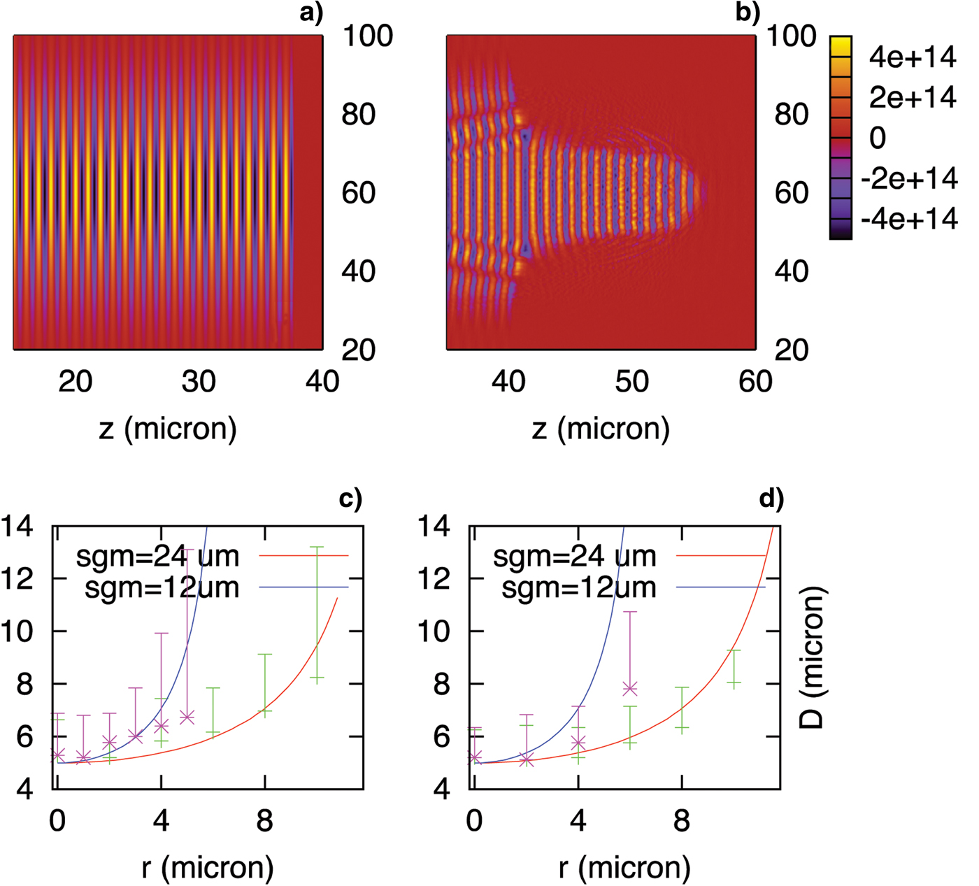
where L represents the thickness of the plasma slab. If we set the longitudinal profile of the Gaussian pulse as 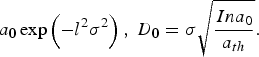 To find D, we numerically integrated Eq. (3). For comparison with simulations, we performed 2D PIC simulations with a long laser pulse with a sharp pulse front (Fig. 5a). Since the intensity of a transversely Gaussian wave decreases as one moves away from the axis, while the plasma density and thickness is uniform, the transmittance also decreases as a function of transverse distance from the axis, leading to a cone-like shape in the pulse front as in Figure 5b. We measured the shaping factor as a function of the transverse position and compared it with the calculation from Eq. (3) (see Figs. 5c and 5d). We represented the measured shaping factor by error-bars, since there was some ambiguity in determining the pulse-cut position due to the noise introduced by laser-plasma interactions. Despite such uncertainty, the overall trends of the measured data follow well the analytic calculation. Such agreement implies that even though the calculation is based on 1D model, it is valid in multidimensional cases to some extent. This point is also verified by the direct measurement of the channeling speed for 2D systems as in Figure 2.

Fig. 4. Definition of the shaping factor.

Fig. 5. (Color online) Pulse shape (a) before and (b) after the transmission through the slab. For (a) and (b), we used a = 120, 24 µm as a spot size, n 0 = 8 × 1022 cm−3, and the slab thickness 2 µm. The rising time of the pulse front was 0.5 fs (sharp-rising). (c), (d) The comparison of the measured and theoretical shaping factors as functions of the transverse distance from the propagation axis with σ = 12 and 24 µm for (c) a = 120, n 0 = 8 × 1022 cm−3 and (d) a = 30, n 0 = 2 × 1022 cm−3.
CONCLUSIONS
In summary, we determined an empirical formula for the speed of the transparency-opacity interface for linearly polarized pulses in overdense plasma. To explain the origin of the empirical formula for the channeling speed, we suggested the concept of a channel opening time, during which the pulse propagates with the group velocity. It is expected that this information about the interface speed would be useful in designing target and laser parameters for laser pulse shaping in over-petawatt regimes. As noted here, based on the formula for the interface speed, it was possible to predict the shaping factor, i.e., the portion of the cut-out by reflection in the pulse front. We also illuminated significant differences in pulse shaping for circularly and linearly polarized pulses.
ACKNOWLEDGMENTS
M.S. Hur was supported by the Basic Science Research Program (grant number: 2011-0005065) through the National Research Foundation of Korea funded by the Ministry of Education, Science and Technology. H. Suk was supported by the National Research Foundation grants (2012-0000165, 2012-0004777). For the simulations, we were supported by the Partnership and Leadership for the nationwide Supercomputing Infrastructure supercomputing resources of the Korea Institute of Science and Technology Information. One of the coauthors, V. Kulagin, was supported by Russian Foundation for Basic Research grant 09-02-01483-a and 11-02-12259-ofi-m-2011.