


I. INTRODUCTION
Enhancing safety for drivers, passengers, and any other road users has been of major interest for any new car generation during the last three decades. While in the beginning the focus was on the mitigation of accident severity, nowadays driver-assistance systems even help to avoid the occurrence of accidents. Due to the strong progress of millimeter-wave technology today automotive radar acts as a key component for modern driver assistance systems [Reference Hasch, Topak, Schnabel, Zwick, Weigel and Waldschmidt1]. Furthermore, radar-based systems migrated from premium to compact car class during recent years [Reference Gresham2, Reference Freundt and Lucas3]. This trend is certainly also due to the advance of silicon–germanium (SiGe) technology [Reference Li, Rein, Suttorp and Böck4] which has also been supported by the public-funded project KOKON [Reference Schneider, Blöcher and Strohm5, Reference Knapp6]. Furthermore, manifold new functions are introduced contributing to the acceptance of driver-assistance systems [Reference Blöcher and Dickmann7]. This variety of applications which can potentially be implemented using radar sensors is illustrated in Fig. 1.
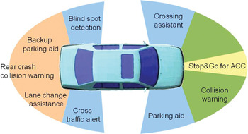
Fig. 1. Radar applications for potential driver assistance systems [Reference Hasch and Waldschmidt8].
In order to address the mass market penetration of radar-based driver-assistance systems and to extend such systems to safety functions the project “Radar on Chip for Cars” (RoCC) has been founded as a successor of the KOKON project. Therefore, “Safety for all” was announced as the driving force for the development of highly integrated and cost-efficient components to aim for the widespread adoption of safety-related driver-assistance systems for urban environments. Bosch participated in achieving these goals by addressing the following key issues:
• System specification:
○ Requirements of future driver-assistance systems
• Sensor concept:
○ Highly integrated radar concept using SiGe Monolithic Microwave Integrated Circuit (MMICs) and novel planar-array antennas for azimuth and elevation angle estimation
• System demonstration and evaluation:
○ Design and validation of proposed sensor concept
• System integration:
○ Evaluation of packaging technologies for SiGe MMICs
In this contribution major outcomes of those work packages will be presented and discussed, which were mainly motivated by three driving forces: firstly, higher integration and the use of wafer level packaging technologies for SiGe MMICs shall allow a more cost-efficient manufacturing and therefore lower the total sensor costs. Secondly, objects are classified by implementing elevation angle estimation. This facilitates to distinguish between relevant and non-relevant objects, which is important for safety functions such as advanced emergency braking systems (AEBS). Finally, lower sensor dimensions compared to previous sensor generations have been achieved to allow a more versatile integration into various vehicles. After describing the requirements for future automotive mid range radar (MRR) the architecture of our proposed sensor concept is illustrated. Subsequently, the emphasis is put on the evaluation of planar array antennas for azimuth and elevation angle estimation in a system demonstrator. In the end, after describing a novel technology for wafer level packaging of 77 GHz MMICs, an outlook is given on an upcoming MRR whose technology is based on the results of this project.
II. SYSTEM SPECIFICATION
Urban environments pose special demands on the sensor requirements as they come with complex driving scenarios and an abundance of different objects. The required applications range from braking aid on convoys of vehicles or crossing objects, up to parking and turn assistants. Furthermore, vehicles and pedestrians participating in those scenarios exhibit a very different radar cross section (RCS), but need to be reliably detected and separated in a wide angular range. As a result, especially the field of view as well as the distance and angular separability have to be considered as essential parameters for the application in urban environments. Therefore, in a first step the specification of those and additional important parameters for future radar sensors have been elaborated and fixed in cooperation with the project partners. The agreed core parameters of the RoCC prototype are listed in Table 1.
Table 1. Specified core parameters for future MRR sensors
(1) Valid for ego velocity below 1·5 m/s.
(2) Valid for ego velocity above 1·5 m/s.
The antenna concept in combination with an appropriate radar architecture and signal processing had to be developed in order to fulfill the requirements stated above. The distance measurement accuracy and range can be accommodated by an adequate antenna gain and aperture, by a low noise architecture of the receiving mixers and by sufficient transmit power of the MMICs. By selecting the frequency band from 77 to 81 GHz, high bandwidth is made available resulting in a distance measurement separability being small enough for urban scenarios. Since the evaluation of different modulation techniques was not in the scope of RoCC, Frequency-modulated continuous-wave (FMCW) modulation has been fixed for this concept. Furthermore, due to a high similarity to existing platforms the influence of new antenna concepts can be evaluated easier. The azimuth and elevation characteristics are determined by the design of antenna and receiver. Since for a mid range sensor a wide field of view has priority on a high distance range, planar-array antennas are ideal to achieve a very compact but powerful design. Therefore, the evaluation of planar array concepts has been a key issue during the RoCC project.
III. SYSTEM DEMONSTRATOR
In order to evaluate the planar antenna concept on a proven and well-known platform, Bosch's third sensor generation of long range radar (LRR3) [Reference Freundt and Lucas3], being on the market since 2009 has been used as a basis for system demonstration. Figure 2 depicts the sensor architecture. The system demonstrator contains two highly integrated printed circuit boards (PCB). The so-called “power-PCB” is similar to the one used in LRR3 sensors. It contains a microcontroller including CAN and Flexray controllers for a powerful signal processing. Furthermore, it comprises a System-Application-specific integrated circuit (ASIC) supplying power to all radar components and additionally providing the CAN interface for the sensor. The so-called “radar-PCB” is a new development. Besides already established SiGe MMICs, this PCB comprises a 19 GHz dielectric resonator oscillator (DRO) for frequency stabilization, a Radar-ASIC developed by Bosch, and the novel planar array antennas. While the ASIC is responsible for FMCW modulation and data acquisition, the MMICs provide two transceiver and two receiver channels. The latter have already been applied in LRR3 sensors and are processed in Infineon's B7HF bipolar SiGe technology. Due to their application in monostatic FMCW architectures, the mixers' large signal immunity has been a key concern during their development. However, the DC offset caused by close-by objects has to be taken into account in subsequent signal processing stages, e.g. by high-pass filtering or by offset compensation techniques [Reference Günther, Steinbuch, Brüggemann, Jäger and Weigel9]. Besides, the receiver gain is 14·2 dB, while each of the two transmit channels provides 7 dBm of output power [Reference Forstner10]. The two transmit channels can be selected among all four channels by a one-mask change during MMIC processing. As a result, this available variability of the outputs gives the required flexibility for various mounting locations in the vehicle.
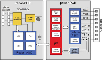
Fig. 2. Sensor architecture of system demonstrator for planar antennas.
Due to the fact that the MMICs are providing two transceiver and two receiver channels, the antenna system is a hybrid of monostatic and bistatic antenna elements see Fig. 3(a). In order to use the full output power and to obtain a narrow transmit beam width two neighboring channels of the MMIC were selected for transceiver operation. As a result, the large part of the available aperture has been allocated by the transmitter antenna consisting of two 4 × 10 patch arrays fed by the two coherent transceiver channels of the MMIC. This leads to a one-way transmit antenna characteristic having a 3 dB beamwidth of 16° and a side lobe suppression of approximately 20 dB. The remaining two receiver channels are connected to two single patch columns. Hence, the one-way receive antenna characteristic of both channels is quite broad while the receive characteristic of both transceiver channels is comparable to their transmit characteristic. However, during transmit operation both channels are coherently fed and therefore act as a single 8 × 10 path array while they are operating independently when receiving. As a result, a 3 dB beamwidth of 24° and a side lobe suppression of about 10 dB can be achieved when receiving. Due to the modified antenna layout changes on the housing had to be carried out. Hence, the dielectric lens of the LRR3 is giving way to a plastic radome that is mounted on the new designed sub-carrier of the housing see Fig. 3(b).

Fig. 3. (a) Top side of “radar-PCB” with SiGe transceiver MMIC and planar antenna arrays and (b) system demonstrator based on LRR3 with modified housing and fixture for the radome.
IV. SYSTEM EVALUATION
Thanks to the high consistency to the current platform, the demonstrator could be evaluated very efficiently by using the same methods and measuring equipment. As the highest novelty of the demonstrator is to be found in its new planar array antenna, the focus of the evaluation has been put on the antenna performance and subsequent signal processing. The two-way azimuth antenna diagram is shown in Fig. 4(a). One can see two sharp drops of power at −25° and +15° in the normalized antenna diagram. Those are caused by zeros in the transmit diagram and lead to inferior angle estimation in this angular range. This fact is also visible in the auto-correlation plot of the demonstrated system illustrated in Fig. 4(b). It is calculated by correlating the amplitude and phase ratios at every angle of the two-way antenna diagram with the ratios at every other angle. Hence, this plot is describing a measure for the quality of angle estimation. It would ideally show a thin red line in its diagonal as this would indicate a perfect accuracy of estimation over the whole angular range. However, imperfections are always present and lead to additional areas of high correlation. If the worst comes to the worst, this in turn could lead to faulty interventions into the driving dynamics. The auto-correlation plot of the demonstrator confirms a very good unambiguousness in the range between −20° and +15°. At higher angles the quality of angle estimation is getting worse, but still not causing objects to be assumed in the central field of view nor changing to the other side of the radar axis.

Fig. 4. (a) Measured two-way antenna diagram and (b) auto-correlation plot of demonstrated system.
The resulting field of view is illustrated in Fig. 5. It is calculated based on the normalized two-way antenna diagram shown in Fig. 4. The calculation considers an object having a RCS of 10 mReference Gresham2 and additionally takes noise, clutter, and the modulation scheme into account. Finally, only those locations are shown at which a signal-to-noise-ratio of at least 10 dB can be obtained, as this level is the approximate threshold of object detection. Due to the fact that this method of determining the sensor's field of view is well-proven and validated by true measurements throughout former sensor generations, it facilitates a fast way to evaluate new antenna concepts. In this certain field of view, one can see that the specified maximum range of 120 m is by far exceeded in the angular range around 0°. Furthermore, the effect of the sharp drops of power can clearly be seen. In those areas the maximum range decreases below 30 m. In the close-up range, objects can be detected within an angular range of ±45° until a distance larger than 20 m.

Fig. 5. Field of view of system demonstrator.
In order to apply safety functions, such as AEBS, future driver-assistance systems will also have to classify the surrounding objects. As a result, radar sensors have to deliver elevation angle information for relevant objects to allow a decision if a certain object can be driven over or emergency braking needs to be triggered. Therefore, another version of the demonstrator has been built to evaluate concepts for elevation angle estimation. In this sensor, one of the transmitting and receiving arrays is replaced by a single transmitting patch column possessing a wider antenna characteristic in azimuth direction and slightly squinting upwards in elevation direction compared to the horizontal plane. As a result, two switchable transmitting channels with different elevation characteristics are made available as illustrated in Fig. 6. Hence, a so-called contrast function can be defined by comparing those two characteristics. The easiest way is to regard the amplitude ratio of both two-way antenna diagrams. Due to their different main lobe widths and their angular offsets, a section of this function does exist in which an unambiguous estimation of the elevation angle can be achieved. For the given example in Fig. 6 this section is highlighted in red. A steep slope of this section will result in a high accuracy of the elevation angle. However, this limits the angular range in which elevation angle estimation can be performed unambiguously. Therefore, a trade-off between the available range for elevation angle estimation and the accuracy of height estimation has to be found by designing both antenna characteristics. A different principle also using series-fed-arrays and additional dielectric lenses has also been demonstrated during the RoCC project [Reference Baur, Mayer, Rack, Vogel and Walter11].

Fig. 6. Principle for elevation angle estimation.
Finally, test runs of the demonstrated system have been carried on public roads. In addition, critical scenarios were reproduced under lab conditions. As aforementioned, the distance measurement separability is crucial for applications in the urban environment. As a result of the specified high-signal bandwidth a good range resolution can be expected. This parameter can be tested by approaching two corner reflectors to the sensor. The system demonstrator already shows a good performance as illustrated in Fig. 7. It depicts the baseband spectrum (green curve) and all detected objects whose response exceeds an adaptive threshold level (red curve) which is approximately 10 dB higher than the local noise floor. Objects within a distance of 40 cm can clearly be distinguished and are furthermore separated by more than one frequency bin in the spectrum. Therefore, the sensor is suitable to provide even better distance measurement separability.

Fig. 7. Baseband spectrum (green) and adaptive threshold level (red) of two close-by corner reflectors in 40 cm radial distance.
Finally, it has to be pointed out that the cause of the above-mentioned constraints lies in this particular antenna design, especially in the chosen amplitude and phase relations among the channels. After completing the RoCC project, several redesign steps have been carried out clearly showing that the antenna characteristics can be improved without major risks during product development. The same applies for the limitation of the range to 30 m in which the maximum distance separability is available. This is mainly due to insufficient memory of the demonstrator's microcontroller which can easily be overcome in future generations. All of the above-mentioned results have laid the foundation for the start of an upcoming MRR platform, which is described in the outlook section.
V. SYSTEM INTEGRATION
Besides increasing the integration density of the MMICs themselves, packaging technology plays a crucial role in achieving the desired cost reduction for mass market penetration. As a result, the goal of an increased ease of handling together with a cost-efficient and robust assembly have been another driving force for system integration aspects during this project.
Wire bonding, also referred to as chip on board (CoB) and flip–chip packaging are the most common technologies used for microwave and millimeter wave transitions. Wire-bonded chips are typically placed into a cavity to allow preferably short bond wires (see Fig. 8). Furthermore they are mounted directly on a thick copper inlay to achieve proper heat dissipation. Beside the need for clean room processes the electrical properties of this packaging technology are not ideal for mass production of radiofrequency (RF) applications. Although an optimized geometry of bond-wires and matching structures can show tolerable return and insertion loss in the frequency range of DC to 80 GHz [Reference Budka12], wiring tolerances up to ±15% and therefore significantly higher losses have to be taken into account [Reference Günther13, Reference Kuang, Kim and Cahill14]. In contrast to CoB packaging, flip-chip components are placed on the PCB upside down using solder balls and underfill. Flip-chip packaging comes with less design constraints, as it allows a more flexible distribution of contact pads within the chip. Furthermore, it provides a better RF performance with reduced radiation losses and improved matching [Reference Jentzsch and Heinrich15]. However, detuning effects due to the close proximity to a substrate or underfill and worse thermal contact have to be mentioned as a downside of this technology.

Fig. 8. CoB packaging: (a) cross-section of a PCB with a wire-bonded SiGe chip and (b) SiGe transceiver chip bonded to RF substrate [Reference Hasch, Topak, Schnabel, Zwick, Weigel and Waldschmidt1].
As any of those packaging technologies requires particular processes which are not compatible to standard Surface-mounted device (SMD) assembly lines this adds extra manufacturing costs. The eWLB (embedded wafer level BGA) package introduced by Infineon Technologies in 2006 [Reference Brunnbauer16] and made available for this project is able to simplify the required process steps. Furthermore, it allows to bridge the so-called “interconnect gap” indicating that the pitch and pad sizes for chips shrink faster than line and space structures on the PCB [17]. The eWLB package is facing this issue by increasing the fan-out area using interposer and redistribution layers (see Fig. 9). Although quite similar approaches have been developed before, it is the first of such packages industrially used in the 77 GHz domain. Due to a minimum interconnection length and a low-loss mold compound a very good electrical performance can be achieved. Measurement results show losses which are just slightly higher compared to on-chip measurements [Reference Wojnowski, Engl, Brunnbauer, Pressel, Sommer and Weigel18, Reference Wojnowski19]. Due to the utilization in the automotive environment, additional challenges had to be overcome to achieve the required reliability. Areas of high mechanical stress can occur because of different coefficients of thermal expansion between chip and mold compound [Reference en Luan20]. Therefore, reliability tests of embedded wafer level packages have been carried out, showing that by choosing a proper mold, compound warpage can be controlled and compliance with industry standards such as JEDEC and AEC-Q100 can be achieved [Reference Brunnbauer, Meyer, Ofner, Mueller and Hagen21]. However, it has been revealed that solder ball fatigue is the dominating failure mode that is directly related to the distance between solder ball and package's neutral point [Reference Meyer, Pressel, Ofner and Romer22]. Hence, this fact is acting as a limiting factor for the amount of RF channels and other I/Os to be implemented in a single package.

Fig. 9. eWLB packaging: (a) cross-section of an embedded SiGe chip soldered on a PCB and (b) close-up view of an eWLB package [Reference Hasch, Topak, Schnabel, Zwick, Weigel and Waldschmidt1].
During this project 6 × 6 mm eWLB packages of four-channel receivers and three-channel transmitters have been evaluated. Measurements and tests did prove a good RF performance and confirmed the required reliability for the automotive environment. Furthermore, the eWLB is a very suitable package for future developments of automotive radar applications as it offers compatibility to 3D layouts [Reference Yoon, Bahr, Baraton, Marimuthu and Carson23] and antenna in package approaches [Reference Al Henawy and Schneider24]. Hence, it will be of great help in doing a leap forward in mass-market production.
VI. OUTLOOK
The outcome of this project has laid the foundation for a recently announced new mid range sensor platform, simply called MRR [Reference Tamang25]. In general, the MRR architecture is comparable to the system demonstrator described above, but in contrast is exhibiting further developed ASICs and a bistatic antenna layout. By using a bistatic architecture, the direct crosstalk between transmitter and receiver is reduced to prevent a degradation of the baseband mixers. As a result, this architecture is better suited for sensor integration behind fascia [Reference Schnabel, Mittelstrass, Binzer, Waldschmidt and Weigel26]. Furthermore, the wire-bonded MMICs of the system demonstrator are replaced by a transmit SiGe MMIC and its counterpart for the receive path, being both packaged in eWLB technology [Reference Wagner27, Reference Knapp28]. As a result, the new platform is able to benefit from state-of-the-art “Pick&Place” processes and a better RF performance [Reference Hildebrandt29]. Two ports of the three-channel transmitter chip are available to feed transmit antennas, while the remaining port provides the LO signal for the four-channel receiver MMIC. Furthermore, in contrast to the MMICs used in the demonstrator, the output power of each transmit channel can now individually be tuned giving more flexibility for the antenna design. Additional constraints of the demonstrator have been removed by developing a new antenna design using two transmitter channels and four receiver channels. The latter are connected to four single-column patch arrays, while the former feed a ten-column patch array and an additional column for the estimation of the elevation angle (see Fig. 10). As a result, a side lobe suppression of better than 30 dB and superior quality of angle estimation in azimuth and elevation could be achieved.

Fig. 10. RF-PCB module of new MRR platform with planar antennas and eWLB packaged MMICs.
The mechanical concept of the MRR is illustrated in Fig. 11. Again the focus was on a robust but cost-efficient design. As a result, in contrast to its predecessor LRR3 no screw joints and no adhesive processes are used. Instead of that, clip-springs provide the necessary holding force for the housing and press both PCBs on the metal sub-carrier. As the majority of heat is dissipated via this sub-carrier, the former metal housing cover of the LRR3 is replaced by a one-piece plastic cover with an integrated car-connector. Furthermore, due to the use of planar antenna arrays the dielectric lens is giving way for a slim radome. Therefore, the sensor features lower dimensions and allows a more versatile vehicle integration.
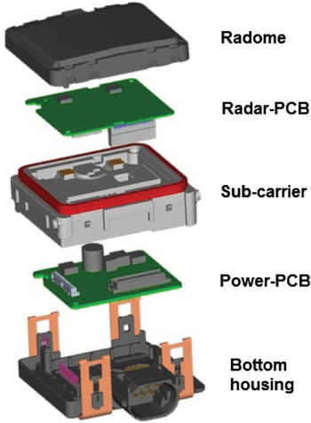
Fig. 11. Exploded view of mechanical concept for new MRR.
VII. CONCLUSION
The development of a new MRR sensor platform for urban environments has been presented. With this new sensor generation, the trends of ongoing cost reduction and extension to safety-related applications shall be continued to achieve “Safety for All” through the mass market penetration of radar-based driver-assistance systems. At the beginning of the development the field of view as well as the distance and angular separability have been identified as core parameters for the specification of future mid range sensors. Furthermore, low sensor dimensions are crucial to allow a more versatile integration into various vehicles and mounting locations. In order to fulfill those requirements, concepts of planar array antennas for azimuth and elevation angle estimation have been designed and evaluated using a system demonstrator. A very good performance of this prototype has been confirmed under lab conditions and on public roads. Constraints that have also been revealed during the evaluation could be removed through redesign steps in the product development phase. Furthermore, a big leap toward an improved cost efficiency could be achieved by implementing eWLB packaged SiGe MMICs instead of wire-bonded chips and by simplifying the mechanical concept of the sensor.
ACKNOWLEDGEMENTS
This work was supported by the German Federal Ministry of Education and Research (BMBF) within the project Radar on Chip for Cars (RoCC). The authors would like to thank all project partners for the close cooperation. In detail we give our thanks to BMW AG and Daimler AG for jointly developing and evaluating requirements and system concepts. Furthermore, we thank Infineon Technologies AG for collaborating in SiGe circuit development and providing SiGe devices during the project. Finally, we like to appreciate the work carried out by all involved research institutions.
 Raik Schnabel was born in Weimar, Germany, in 1985. He received the Dipl.-Ing. degree in Electrical Engineering in 2010 from the Karlsruhe Institute of Technology, Karlsruhe, Germany. Currently, he is pursuing the Ph.D. degree at the business unit “Chassis Systems Control” of the Robert Bosch GmbH, Stuttgart, Germany. His main interests are millimeter-wave integrated circuits for Automotive Radar.
 Raphael Hellinger was born in Pforzheim, Germany, in 1982. He received the Dipl.-Ing. degree in Electrical Engineering in 2007 from the University of Stuttgart, Stuttgart, Germany. Since 2007, he is with the business unit “Chassis Systems Control” of the Robert Bosch GmbH, Leonberg, Germany, where he is currently working on antenna systems for Automotive Radar.
 Dirk Steinbuch was born in Freiburg, Germany, in 1967. He received the Dipl.-Ing. degree in 1993 from the Technical University of Karlsruhe, Germany. From 1994 to 1998, he worked as an RF expert in the Automotive Radar development with M/A-COM ETAC in Schweinfurt, Germany (now operating as Autoliv). From 1998 to 2000, he was a Senior RF expert with M/A-COM in Lowell, MA, USA. In 2000, he joined the Robert Bosch GmbH and is currently working on development and application of millimeter-wave integrated circuits for Automotive Radar. He is author and co-author of over 40 patents.
 Joachim Selinger was born in Stuttgart, Germany in 1967. He received his Dipl.-Ing. degree in Electrical Engineering in 1995 from the University of Stuttgart, Germany. From 1992 to 1994, he studied at the University of Colorado in Boulder and received his M.S. in 1994. From 1995 to 2002, he was research assistant at the Institute for Network and Systems Theory (University of Stuttgart). In 2002, he joined the corporate research and development of the Robert Bosch GmbH to work in the field of driver assistance systems. Since 2011, he is responsible for series development support of automotive radar sensors
 Michael Klar was born in Tübingen, Germany, in 1972. He received his Ph.D. degree in RF-technology in 2002 from the Technical University of Stuttgart, Germany. Since 2001, he is working in different roles within the radar development. Currently, he is project director of the 4th generation radar sensors from the Robert Bosch GmbH at the business unit “Chassis Systems Control”.
 Bernhard Lucas was born in Panker, Germany, in 1953. He received the Dipl.-Ing. degree in 1985 from the Fachhochschule Braunschweig-Wolfenbüttel, Germany. He joined the Robert Bosch GmbH in 1985 and has worked in several different development areas. In 1995, he joined the automotive radar hardware development. Currently, he is working as a director for the development of components and digital signal processing of 77 GHz Automotive Radar. In 2005, he received the prize “Gelber Engel” from the German Automobile Club (ADAC) as representative of the team for the innovation of Predictive Safety Systems.


